Sense 3d scanners
Sense Handheld 3D Scanner Review
Skip to main contentWhen you purchase through links on our site, we may earn an affiliate commission. Here’s how it works.
If you have a 3D printer, you have probably downloaded and printed a few objects, and then moved on to building your own — only to realize that 3D modeling is difficult. Often, it is easier to model an object in clay and then scan it, or just scan an existing object. That's what the $400 Sense 3D scanner from 3D Systems does: scans an object and creates a 3D model that can be modified on a computer and printed from a 3D printer or online printing service.
Overall, it does a good job of scanning large objects quickly and producing high-quality 3D models. It does have limitations, though: It can't do small objects, doesn't always pick up fine details and can't handle transparent or shiny objects.
How the Sense 3D works
The Sense 3D scanner itself is pretty light, and looks like it could double as a ray gun at a sci-fi convention. You hold it in your hand and move around the object to scan it. The scanner projects a patterned infrared (IR) beam onto the object from the bottom opening that is then detected by the middle webcam. On the PC (Windows only), the included software then translates the information into the shape of the object. At the top of the Sense is a normal webcam, which the same software uses to translate the images it captures into the surface colors of the object.
MORE: Best 3D Printers
If this process sounds rather familiar, it's because it is the same technology used in the first-generation Microsoft Kinect camera for the Xbox, created by a company called PrimeSense (which was recently acquired by Apple). A similar setup is used by the Scenect and ReconstructMe software, both of which can use a Microsoft Kinect sensor to create 3D scans. The Sense 3D comes with its own scanner, but the technology inside it is the same.
A candy bowl on a metal pedestal (left).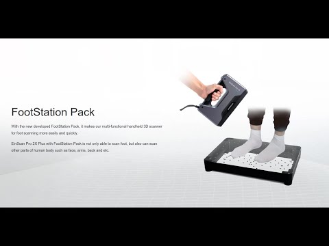 The scan failed to detect the glass portion (right)
 The scanning process is fairly simple: You start the software and choose the size of the object, with options for a person (head and shoulders, or full body), or for a size range: from small (at least 8 inches, or 20 centimeters), to large (up to 10 feet, or 3 meters).
As prompted by the software, you point the scanner at the object, hit the space bar and walk around it, following a series of on-screen prompts that try to keep you the right distance from the object, and track the object as you move. If you are too far away, or it looses track of the object, you are notified with a beep and an on-screen note in the software. You can then try to reacquire the target by matching a ghost image of the last capture with the live overlay on the screen.
While the scan is in progress, the software creates a rough model of the object that is painted in as it detects the shape. This modeled object rotates with the scanner, but you can pause it (with the space bar) and rotate around it with the right mouse button. Pressing the space bar again restarts the scanning process, so you can check the scan and then continue.
How well the Sense 3D works
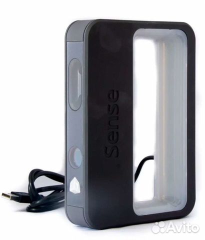
The scanner has a few minor annoyances. For example, the attached 6.75-foot (2-meter) USB cable isn't long enough to move the scanner very far from the computer. This means that when scanning a large object (such as a person), you have to carry both the scanner and the computer around as you scan, or buy a USB extension cable. A wireless connection (such as Wi-Fi or Bluetooth) would have been preferable here, and would have made the scanner more flexible. A way to start or pause the scan from the scanner itself, rather than using the keyboard, also would have been beneficial.
From the left: a 19-inch tall figure, the 3D scan, and a 3D print produced on a MakerBot Replicator.A bigger problem is that the scanner struggles with some objects — particularly, shiny, transparent or extremely matte-black ones. This is because such surfaces don't reflect the IR light pattern well. This can lead to either the object not being detected at all, or a grossly distorted version showing up in the scan. When scanning my head, for instance, the scanner failed to detect my thin, shiny, metal glasses, and instead interpreted them as part of my face, which made scans of my head look as though I was wearing a crime-fighter mask. (Staff writer Jill Scharr had better luck, after she removed her glasses.)
What can it scan?
The Sense 3D works best with medium-size objects. Although the product specs claim that the scanner can spot details down to a resolution of 0.9 mm, I found that small details on small objects were not accurately captured. The details of cherubs forming the base of an 8-inch-tall candy dish, for instance, were only roughly recognizable in the final scan, even though all the details were larger than 0.9 mm.
3D Systems says the smallest scannable object is a cube measuring 0.2 meters (just less than 8 inches) on each side, and that seems like a good baseline — anything smaller than a loaf of bread is unlikely to scan well. If you intend to scan smaller subjects, you might do better with the MakerBot Digitizer , which is designed for objects that would fit within an 8-inch-high by 8-inch-wide cylinder. But be prepared to pay more: It retails for $1,400 (though you can likely find it cheaper).
At the other end of the scale, the system can scan large objects up to 3 meters (just under 10 feet) on each side. That's enough for things like small couches or motorcycles. Cars are too big; they won't fit entirely into the scanner's field of view.
MORE: MakerBot 3D Scanner: 12 Minutes from Physical to Virtual
The system lets you rotate the object rather than the scanner (if you wish), so you can do head-and-shoulders scans on a rotating chair, or put someone or something on a motorized turntable. The lighting does have to be very even for this to work, though: If it is not, you get odd colors in the final model from the shadows as the subject rotates.
The scanning process also needs a lot of light. If part of the object is in a shadow or low light, the colors come out dull and muted, and the scanner struggles to track the object. Bright lights behind the object also confuse it (especially the sun, which gives off lots of IR light), again producing odd shapes or, more often, a loss of tracking, in which the system can't find the object in the image (an endemic problem with cheap 3D scanning apps).
I got the best results from scans done in bright but diffuse light, such as indirect sunlight, or with several softened surrounding electric lights. If you are planning to do a lot of scans with this device, it might be worth building a 360-degree lighting setup. If you are scanning outdoors, you should pick your location carefully and shoot with the sun high in the sky so it doesn't end up shining into the scanner and confusing it as you move around.
The results
Once the scan is complete, the program processes all of the scanned data and gives you the 3D model. You can then edit this, cutting out the bits that you don't need, (such as the surface that an object was sitting on or other nearby objects) and smoothing the object. This process is fairly intuitive: If you are comfortable using the mouse, you'll quickly learn how to edit objects.
You can also set the software to solidify the object, which fills in small parts that the scan misses, such as areas that are partially covered, or those that are too dark to be detected. However, this technique should be used with caution, as it can't fill in any larger missing parts of a scan. One scan I did of a deck chair missed parts of the legs, and the solidify feature mistakenly created a huge, solid mass underneath the chair rather than just filling in the missing sections of the leg.
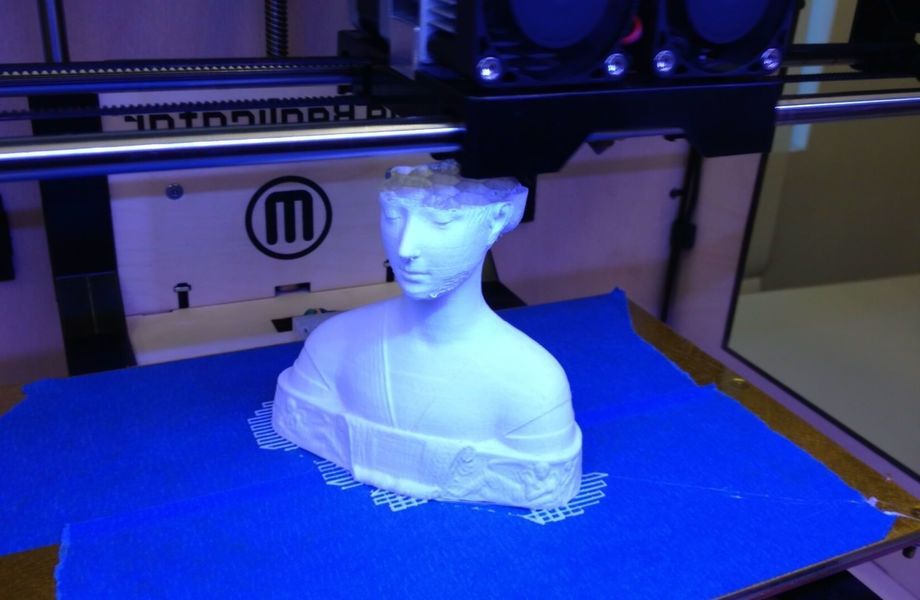
The process generally produced good results with larger, well-lit objects that don't have overlapping elements or large holes in them, like people. It did an impressive job with both a head-and-shoulders scan and a full-person scan, building the 3D mesh (the mesh of scanned points and surfaces that form the object) and then creating a simple final object from this data.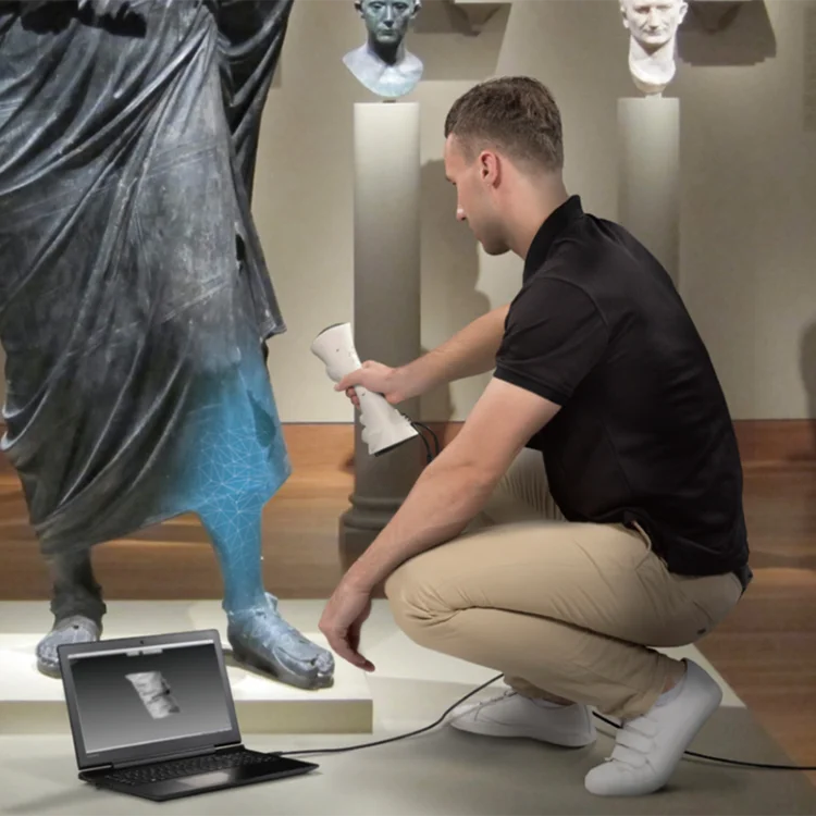
MORE: 3D Printer Buyer's Guide
A scan of staff writer Jill Scharr after she removed her glasses.When the scan is finalized, it can be exported as a STL, PLY or OBJ file, which will work with most 3D design software. STL files are the most widely used, but they don't include any of the color information from the object. PLY and OBJ files do include this information, so those are the best formats to work with if you want to print the objects to a full-color process. Unsurprisingly, the Sense software links directly to 3D Systems' Cubify object service, where you can order a 3D print that will be shipped to you. This service also allows you to sell the 3D scan itself, or a 3D-printed model in various sizes and materials that Cubify's online printing service offers.
The 3D Sense is a capable scanner, but it is limited by the capabilities of the scanning system it employs. The PrimeSense sensor it uses is capable of decent resolution, but it can't detect and resolve the same level of fine detail that scanners like the MakerBot Digitizer or the David SLS-1 can; it just isn't suited for scanning the smaller objects that these printers can.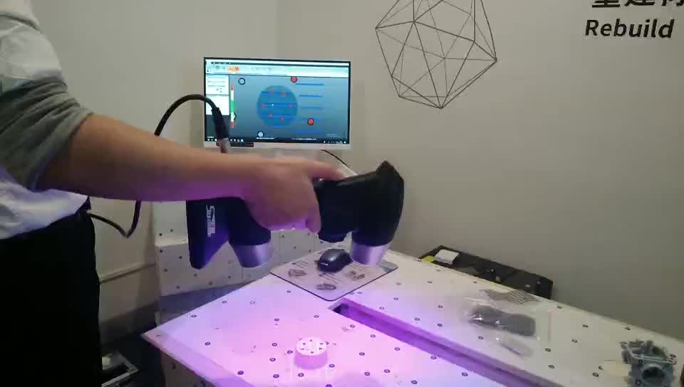 It can't scan very large objects (bigger than about 10 feet), either, so it is best suited for subjects like people and statues. For these types of things, the 3D Sense does a great job of creating a decent 3D model. The process of scanning has its quirks, but it is generally easy to do once you figure them out, and it produces attractive 3D objects that can be quickly and easily printed.
Swipe to scroll horizontally
| Pros | Cons |
| Inexpensive | USB cable too short |
| Easy to operate | Doesn't scan objects as small as promissed |
| Scans very large objects | Lighting objects is a bit tricky |
Dimensions
7 inches x 5 inches x 1. 2 inches (17.8 cm x 12.9 cm x 3.3 cm)
Scan volume
Min: 7.8 inches x 7.8 inches x 7.8 inches (20 cm x 20 cm x 20 cm)
Max: 9.8 feet by 9.8 feet x 9.8 feet (3 m x 3 m x 3 m)
Field of view
Horizontal: 45 degrees
Vertical: 57.5 degrees
Diagonal: 69 degrees
Minimum hardware recommendations
Intel Core i5™ or equivalent processor
2GB of RAM
1280 x 1024-pixel screen resolution
32-bit color
4GB available disk space
Windows 7, Windows 8, Windows 8.1 (32-bit or 64-bit)
(No Mac OS X support)
Follow Richard Baguley @rbaguley on Twitter, or on Google+. Follow us @TomsGuide, on Facebook and on Google+.
- Scanners could bring 3D objects to the masses
- Forget Plastic: Molten Metal 3D Printers Are Coming
- 5 Coolest 3D Printers of Maker Faire 2013
Get instant access to breaking news, the hottest reviews, great deals and helpful tips.
Richard Baguley has been working as a technology writer and journalist since 1993. As well as contributing to Tom's Guide, he writes for Cnet, T3, Wired and many other publications.
Topics
Gadgets
Tom's Guide is part of Future US Inc, an international media group and leading digital publisher. Visit our corporate site .
© Future US, Inc. Full 7th Floor, 130 West 42nd Street, New York, NY 10036.
Sense™ - Protocom s.r.o.
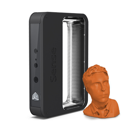
Capture your world in 3D and discover the power of physical photography with the Sense 3D scanner. Savor every dimension of your favorite memories: Graduation day. Wedding day. Bringing home baby. Holidays. Trips around the world. All with your Sense, all in 3D.
Scan small, scan large, scan it all
Sense 3D scanner scans small and large objects, people and scenes. The Sense 3D scanner has the most diverse scan range in its class with auto-optimized settings for small and large objects like a book or a motorcycle, heads to full bodies and scenes as large as 10 feet tall and wide.
Mash-up your world
Merge your scans in Cubify Sculpt™, the ultimate consumer software for editing STLs, mash-ups and organic modeling. Full integration between the Sense 3D scanner and Cubify Sculpt gives you the creative freedom to import your scans and combine them with other favorite designs.
Zero in on what matters
Automatic object recognition extracts precise targets from the busiest of backgrounds, scanning only the object you want.
Edit confidently
Sense 3D scanner software is intuitive, fast, accurate and easy to use. Scans process in seconds and can be cropped, enhanced and solidified for printables in just minutes. No design experience is necessary.
For your life on the go
Hand-held mobility gives you the freedom to scan spontaneously, everywhere you go.
Physical to digital and back again
Sense 3D scanner is fully integrated with Cubify.com and your Cube 3D printer. Scans can be uploaded directly for cloud printing with a variety of materials on Cubify.com, or sent directly to your 3D printer.
System Requirements
PC
- Intel® Core i5™ or equivalent processor
- RAM: 2 GB minimum
- 1280 x 1024 minimum screen resolution
- Colour: 32-bit
- 4 GB available hard disk space
MAC
- Intel® Core i5™ or equivalent processor
- RAM: 4 GB minimum
- Mac OS X 10.8 or later
- 64-bit O/S
- Sense FFB.pdf (pdf - 147 kB)
- Sense flyer.pdf (pdf - 652 kB)
Technical Specifications
| Dimensions | 17. 8 cm × 12.9 cm × 3.3 cm 8 cm × 12.9 cm × 3.3 cm |
|---|---|
| Scan volume | Min: 0.2 × 0.2 × 0.2 m - Max: 3 × 3 × 3 m |
| Depth image size | 240 (w) × 320 (h) px |
| Field of view | Horizontal: 45°, Vertical: 57.5°, Diagonal: 69° |
| Operating range | Min. 0.35 m - Max: 3 m |
| Operating temperature | 10-40° C |
| Depth resolution @ 0.5 m | 1 mm |
| Warranty | 1 year |
| Spatial x/y resolution @ 0.5 m | 0.9 mm |
| Max power consumption | 2.25 watts |
| Data interface | USB 2. 0 / USB 3.0 0 / USB 3.0 |
| Data format | 16 bit |
| Colour Image Size | 240 (w) × 320(h) px |
Video
All about 3D scanners: from varieties to applications
The 3D scanner is a special device that analyzes a specific physical object or space in order to obtain data on the shape of an object and, if possible, its appearance (for example , about color). The collected data is then used to create a digital three-dimensional model of this object.
To create 3D-scanner allows several technologies at once, differing from each other in certain advantages, disadvantages, as well as cost. In addition, there are some restrictions on the objects that can be digitized. In particular, there are difficulties with objects that are shiny, transparent or have mirror surfaces.
Don't forget that 3D data collection is also important for other applications. So, they are needed in the entertainment industry to create films and video games. Also, this technology is in demand in industrial design, orthopedics and prosthetics, reverse engineering, prototyping, as well as for quality control, inspection and documentation of cultural artifacts.
Functionality
The purpose of the 3D Scanner is to create a point cloud of geometric patterns on the surface of an object. These points can then be extrapolated to recreate the shape of the object (a process called reconstruction). If color data were obtained, then the color of the reconstructed surface can also be determined.
3D scanners are a bit like regular cameras. In particular, they have a cone-shaped field of view, and they can only receive information from surfaces that have not been darkened. The difference between these two devices is that the camera transmits only information about the color of the surface that fell into its field of view, but the 3D scanner collects information about the distances on the surface, which is also in its field of view.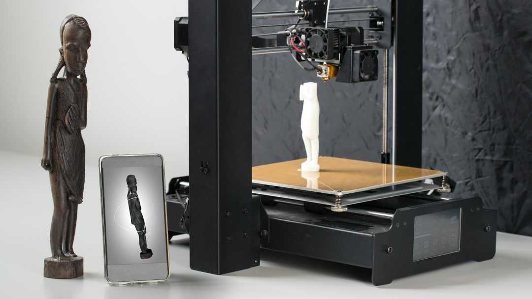 Thus the "picture" obtained with of the 3D scanner, describes the distance to the surface at each point in the image. This allows you to determine the position of each point in the picture in 3 planes at once.
In most cases, one scan is not enough to create a complete model of the object. Several such operations are required. As a rule, a decent number of scans from different directions will be needed in order to obtain information about all sides of the object. All scan results must be normalized to a common coordinate system, a process called image referencing or alignment, before a complete model is created. This whole procedure from a simple map with distances to a full-fledged model is called a 3D scanning pipeline.
Technology
There are several technologies for digitally scanning a mold and creating a 3D model of an object. However, a special classification has been developed that divides 3D scanners into 2 types: contact and non-contact. In turn, non-contact 3D scanners can be further divided into 2 groups - active and passive. Several technologies can fall under these categories of scanning devices.
Coordinated-measuring machine with two fixed mutually perpendicular measuring hands
Contact 3D scanners
Contact 3D-scanners Explore (probes) the object directly through physical contact, while the subject itself is expected to explode itself on a precision surface plate, ground and polished to a certain degree of surface roughness. If the scanned object is uneven or cannot lie stably on a horizontal surface, then a special vise will hold it.
The scanner mechanism comes in three different forms:
- Carriage with a fixed measuring arm positioned perpendicularly, and measurement along the axes occurs while the arm slides along the carriage. This system is optimal for flat or regular convex curved surfaces.

- Fixed component manipulator with high precision angle sensors. The location of the end of the measuring arm entails complex mathematical calculations regarding the angle of rotation of the wrist joint, as well as the angle of rotation of each of the joints of the arm. This mechanism is ideal for probing recesses or interior spaces with a small inlet.
- Simultaneous use of the previous two methods. For example, a manipulator can be combined with a carriage, which allows you to get 3D data from large objects that have internal cavities or overlapping surfaces. The
CMM (coordinate measuring machine) is a prime example of the contact 3D scanner . They are used mainly in manufacturing and can be ultra-precise. The disadvantages of CMM include the need for direct contact with the surface of the object. Therefore, it is possible to change the object or even damage it. This is very important if thin or valuable items such as historical artifacts are being scanned. Another disadvantage of CMM over other scanning methods is slowness. Moving the measuring arm with the probe in place can be very slow. The fastest result of CMM operation does not exceed a few hundred hertz. At the same time, optical systems, for example, a laser scanner, can operate from 10 to 500 kHz.
Another example is hand-held measuring probes used to digitize clay models for computer animation.
The Lidar device is used to scan buildings, rocks, etc., which makes it possible to create 3D models of them. The Lidar laser beam can be used in a wide range: its head rotates horizontally, and the mirror moves vertically. The laser beam itself is used to measure the distance to the first object in its path.
Non-contact active scanners
Active scanners use certain types of radiation or just light and scan an object through the reflection of light or the passage of radiation through an object or medium.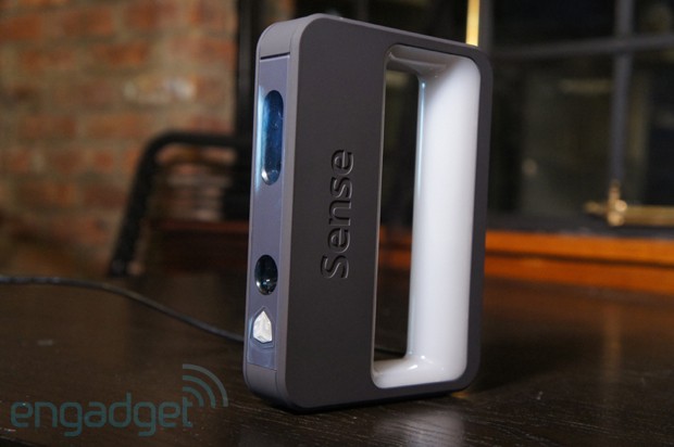 These devices use light, ultrasound, or x-rays.
Time-of-Flight Scanners
Time-of-Flight Laser Scanner The 3D scanner is an active scanner that uses a laser beam to examine an object. This type of scanner is based on a time-of-flight laser range finder. In turn, the laser rangefinder determines the distance to the surface of the object, based on the time of flight of the laser back and forth. The laser itself is used to create a pulse of light, while the detector measures the time until the light is reflected. Given that the speed of light (c) is a constant value, knowing the time of flight of the beam back and forth, you can determine the distance over which the light has moved, it will be twice the distance between the scanner and the surface of the object. If (t) is the round-trip flight time of the laser beam, then the distance will be (c*t\2). Laser beam time-of-flight accuracy of the 3D scanner depends on how accurately we can measure time (t) itself: 3. 3 picoseconds (approximately) is needed for the laser to travel 1 millimeter.
The laser distance meter determines the distance of only one point in a given direction. Therefore, the device scans its entire field of view in separate points at a time, while changing the direction of scanning. You can change the direction of the laser rangefinder either by rotating the device itself, or using a system of rotating mirrors. The latter method is often used, because it is much faster, more accurate, and also easier to handle. For example, time-of-flight 3D scanners can measure distance from 10,000 to 100,000 points in one second.
TOF devices are also available in 2D configuration. Basically, this applies to time-of-flight cameras. Triangulation scanners Two positions of the object are shown.
A point cloud is generated by triangulation and a laser stripe.
Triangulation laser scanners The 3D scanners are also active scanners that use a laser beam to probe an object.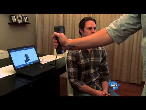 Like the time-of-flight 3D scanners, triangulation devices send a laser to the scanned object, and a separate camera captures the location of the point where the laser hit. Depending on how far the laser travels across the surface, the dot appears at different locations in the camera's field of view. This technology is called triangulation because the laser dot, the camera and the laser emitter itself form a kind of triangle. The length of one side of this triangle is known - the distance between the camera and the laser emitter. The angle of the laser emitter is also known. But the camera angle can be determined by the location of the laser dot in the field of view of the camera. These 3 indicators completely determine the shape and size of the triangle and indicate the location of the corner of the laser point. In most cases, to speed up the process of obtaining data, a laser strip is used instead of a laser dot. Thus, the National Research Council of Canada was among the first scientific organizations that developed the basics of triangulation laser scanning technology back in 1978 year.
Advantages and disadvantages of
scanners Both time-of-flight and triangulation scanners have their own strengths and weaknesses, which determines their choice for each specific situation. The advantage of time-of-flight devices is that they are optimally suited for operation over very long distances up to several kilometers. They are ideal for scanning buildings or geographic features. At the same time, their disadvantages include measurement accuracy. After all, the speed of light is quite high, so when calculating the time it takes for the beam to overcome the distance to and from the object, some flaws (up to 1 mm) are possible. And this makes the scan results approximate.
As for triangulation rangefinders, the situation is exactly the opposite. Their range is only a few meters, but the accuracy is relatively high. Such devices can measure distance with an accuracy of tens of micrometers.
The study of the edge of an object negatively affects the accuracy of the TOF scanners. The laser pulse is sent one, and is reflected from two places at once. The coordinates are calculated based on the position of the scanner itself, and the average value of the two reflections of the laser beam is taken. This causes the point to be defined in the wrong place. When using scanners with high resolution, the chances that the laser beam hits the exact edge of the object increase, but noise will appear behind the edge, which will negatively affect the scan results. Scanners with a small beam can solve the edge scanning problem, but they have limited range, so the beam width will exceed the distance. There is also special software that allows the scanner to perceive only the first reflection of the beam, while ignoring the second.
At 10,000 dots per second, low resolution scanners can do the job within seconds. But for scanners with high resolution, you need to do several million operations, which will take minutes. It should be borne in mind that the data may be distorted if the object or the scanner moves. So, each point is fixed at a certain point in time in a certain place. If the object or scanner moves in space, then the scan results will be false. That's why it's so important to mount both the object and the scanner on a fixed platform and keep the possibility of vibration to a minimum. Therefore, scanning objects in motion is practically impossible. Recently, however, there has been active research on how to compensate for the effect of vibration on data corruption.
It is also worth considering that when scanning in one position for a long time, a slight movement of the scanner may occur due to temperature changes. If the scanner is mounted on a tripod and one side of the scanner is exposed to strong sunlight, then the tripod will expand and the scan data will gradually distort from one side to the other. However, some laser scanners have built-in compensators that counteract any movement of the scanner during operation.
Conoscopic holography
In the conoscopic system, a laser beam is projected onto the surface of an object, after which the beam is reflected along the same path, but through a conoscopic crystal, and is projected onto a CCD (charge-coupled device).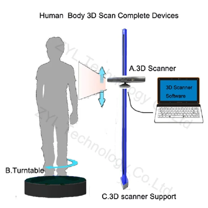 The result is a diffraction pattern from which frequency analysis can be used to determine the distance to the surface of an object. The main advantage of conoscopic holography is that only one beam path is needed to measure the distance, which makes it possible to determine, for example, the depth of a small hole.
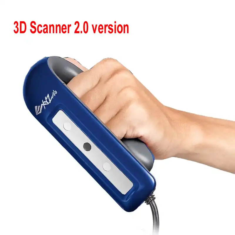
Handheld laser scanners
Handheld laser scanners create a 3D image using the triangulation principle described above. A laser beam or stripe is projected onto an object from a hand-held emitter, and a sensor (often a CCD or position-sensitive detector) measures the distance to the surface of the object. The data is collected relative to the internal coordinate system and therefore, to obtain results, if the scanner is in motion, the position of the device must be accurately determined. This can be done using basic features on the scanned surface (adhesive reflective elements or natural features) or using the external tracking method. The latter method often takes the form of a laser tracker (providing a position sensor) with a built-in camera (to determine the orientation of the scanner). You can also use photogrammetry, provided by 3 cameras, which gives the scanner six degrees of freedom (the ability to make geometric movements in three-dimensional space). Both techniques typically use infrared LEDs connected to the scanner. They are observed by cameras through filters that ensure the stability of ambient lighting (reflecting light from different surfaces).
Scan data is collected by a computer and recorded as points in 3D space, which after processing are converted into a triangulated grid. The computer-aided design system then creates a model using a non-uniform rational B-spline, NURBS (a special mathematical form for creating curves and surfaces). Handheld laser scanners can combine this data with passive visible light sensors that capture surface texture and color to create or reverse engineer a complete 3D Models .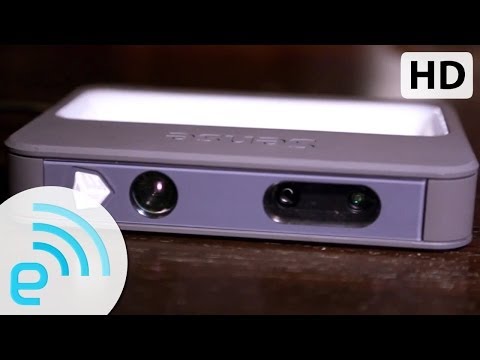
Structured light
3D scanners, working on structured light technology, represent a projection of a light grid directly onto an object, deformation of this pattern and is a model of the scanned object. The grid is projected onto the object using a liquid crystal projector or other constant light source. A camera positioned just to the side of the projector captures the shape of the network and calculates the distance to each point in the field of view.
Structured light scanning is still an active area of research, with quite a few research papers devoted to it each year. Ideal maps are also recognized as useful as structured light patterns that can solve matching problems and allow errors to be corrected as well as detected.
The advantage of the Structured Light 3D Scanners is their speed and accuracy. Instead of scanning one point at a time, structured scanners scan several points at the same time or the entire field of view at once. Scanning the entire field of view takes a fraction of a second, and the generated profiles are more accurate than laser triangulations. This completely solves the problem of data corruption caused by motion. In addition, some existing systems are capable of scanning even moving objects in real time. For example, the VisionMaster, a 3D scanning system, has a 5-megapixel camera, so each frame contains 5 million dots.
Real-time scanners use digital edge projection and a phase-shifting technique (one of the techniques for using structured light) to capture, reconstruct and create a high-density computer model of dynamically changing objects (such as facial expressions) at 40 frames per second. A new type of scanner has recently been created. Various models can be used in this system. The frame rate for capturing and processing data reaches 120 frames per second. This scanner can also process individual surfaces. For example, 2 moving hands. Using the binary defocusing method, the shooting speed can reach hundreds or even thousands of frames per second.
Modulated light
When using the 3D scanners based on modulated light, the light beam directed at the object is constantly changing. Often the change of light passes along a sinusoid. The camera captures the reflected light and determines the distance to the object, taking into account the path that the light beam has traveled. Modulated light allows the scanner to ignore light from sources other than the laser, thus avoiding interference.
Volumetric techniques
Medical
Computed tomography (CT) is a special medical imaging technique that creates a series of two-dimensional images of an object, a large three-dimensional image of the internal space. Magnetic resonance imaging works on a similar principle - another imaging technique in medicine, which is distinguished by a more contrast image of the soft tissues of the body than CT. Therefore, MRI is used to scan the brain, the musculoskeletal system, the cardiovascular system, and to search for oncology. These techniques produce volumetric voxel models that can be rendered, modified, and transformed into a traditional 3D surface using isosurface extraction algorithms.
Production
Although MRI, CT or microtomography are more widely used in medicine, they are also actively used in other areas to obtain a digital model of an object and its environment. This is important, for example, for non-destructive testing of materials, reverse engineering or the study of biological and paleontological samples.
Non-contact passive scanners
Passive scanners do not emit light, instead they use reflected light from the environment. Most scanners of this type are designed to detect visible light, which is the most accessible form of ambient radiation. Other types of radiation, such as infrared, may also be involved.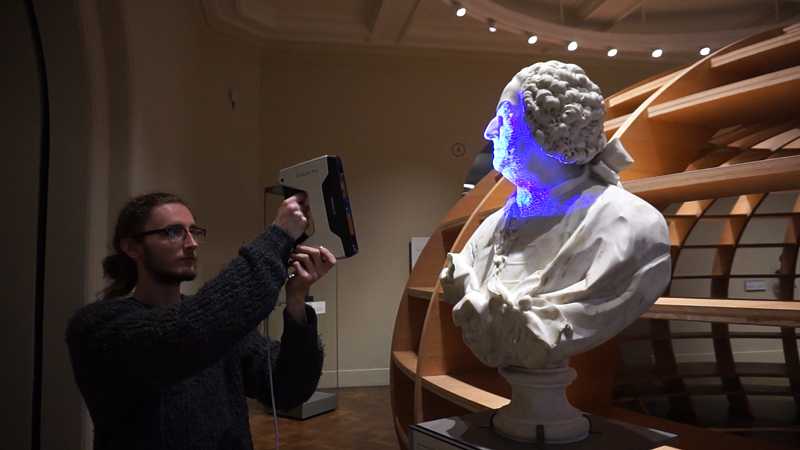 Passive scanning methods are relatively cheap, because in most cases they do not need special equipment, a conventional digital camera is enough.
Stereoscopic systems involve the use of 2 video cameras located in different places, but in the same direction. By analyzing the differences in the images of each camera, you can determine the distance to each point in the image. This method is similar in principle to human stereoscopic vision.
Photometric systems typically use a single camera that captures multiple frames in all lighting conditions. These methods attempt to transform the object model in order to reconstruct the surface for each pixel.
Silhouette techniques use contours from successive photographs of a three-dimensional object against a contrasting background. These silhouettes are extruded and transformed to get the visible skin of the object. However, this method does not allow you to scan the recesses in the object (for example, the inner cavity of the bowl).
There are other methods that are based on the fact that the user himself discovers and identifies some features and shapes of the object, based on many different images of the object, which allow you to create an approximate model of this object. Such methods can be used to quickly create a three-dimensional model of objects of simple shapes, for example, a building. You can do this using one of the software applications: D-Sculptor, iModeller, Autodesk ImageModeler or PhotoModeler.
This 3D scan is based on the principles of photogrammetry. In addition, this technique is in some ways similar to panoramic photography, except that the photographs of the object are taken in three-dimensional space. Thus, it is possible to copy the object itself, rather than taking a series of photos from one point in three-dimensional space, which would lead to the reconstruction of the object's environment.
Reconstruction
From point clouds
The point clouds generated by the 3D Scanners can be directly used for measurement or visualization in architecture and engineering.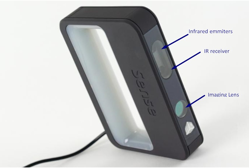
However, most applications use non-homogeneous rational B-spline, NURBS, or editable CAD models (also known as solid models) instead of polygonal 3D models.
- Polygon mesh models: In polygon representation shapes curved surfaces consist of many small flat surfaces with edges (a striking example is a ball in discotheques). Polygonal models are very in demand for visualization in the field of CAM - an automated system for technological preparation of production (for example, mechanical processing). At the same time, such models are quite « heavy" (accommodate a large amount of data) and are quite difficult to edit in this format. Reconstruction into a polygonal model involves searching and combining neighboring points with straight lines until a continuous surface is formed. For this, you can use a number of paid and free programs (MeshLab, Kubit PointCloud for Au toCAD, 3D JRC Reconstructor, ImageModel, PolyWorks, Rapidform, Geomagic, Imageware, Rhino 3D, etc.).
- Surface models: This method represents the next level of sophistication in the field of modeling.
 It applies a set of curved surfaces that give your object its shape. It can be NURBS, T-Spline or other curved objects from the topology. Using NURBS converts, for example, a sphere to its mathematical equivalent. Some applications require manual processing of the model, but more advanced programs also offer automatic mode. This option is not only easier to use, but also provides the ability to modify the model when exporting to a computer-aided design system (CAD). Surface models are editable, but only in a sculptural way. Organic and artistic forms lend themselves well to modeling. Surface modeling is available in Rapidform, Geomagic, Rhino 3D, Maya, T Splines.
 - 3D CAD Models: From an engineering and manufacturing perspective, this type of simulation is a full digitized form of a parametric CAD model. After all, CAD is the industry's common "language" for describing, editing, and preserving the shape of an enterprise's assets. For example, in CAD, a sphere can be described by parametric functions that are easy to edit by changing their value (say, radius or center point).

These CAD models don't just describe the shell or shape of an object, but they also enable design intent (ie, critical features and their relationship to other features). An example of design intent that is not expressed in form would be the ribbed bolts of a brake drum, which should be concentric with the hole in the center of the drum. This nuance determines the sequence and method of creating a CAD model, so the engineer, taking into account these features, will develop bolts tied not to the outer diameter, but, on the contrary, to the center. Thus, to create such a CAD model, you need to correlate the shape of the object with the design intent.
There are several approaches to get a parametric CAD model. Some involve only exporting a NURBS surface, leaving the CAD engineer to complete the modeling (Geomagic, Imageware, Rhino 3D). Others use the scan data to create an editable and verifiable function model that can be fully imported into CAD with an intact fully functional tree, providing a complete fusion of shape and design intent of the CAD model (Geomagic, Rapidform). However, other CAD applications are powerful enough to manipulate a limited number of points or polygonal models in a CAD environment (CATIA, AutoCAD, Revit).
From the 2D slice set
3D reconstruction of the brain or eyeballs based on CT results is performed using DICOM images. Their peculiarity is that the areas on which air is displayed, or bones with a high density are made transparent, and the sections are superimposed in a free alignment interval. The outer ring of biomaterial surrounding the brain is made up of the soft tissues of the skin and muscles on the outside of the skull. All sections are made on a black background. Since they are simple 2D images, when added one-to-one when viewed, the borders of each slice disappear due to their zero thickness. Each DICOM image is a slice about 5 mm thick.
CT, industrial CT, MRI or microCT scanners do not create a point cloud, but 2D slices (referred to as a “tomogram”) that are superimposed on each other, resulting in a kind of 3D model. There are several ways to do this, depending on the desired result:
- Volume rendering: Different parts of an object usually have different thresholds and grayscale densities. Based on this, a three-dimensional model can be freely designed and displayed on the screen. Several models can be made from different thresholds, allowing different colors to represent a specific part of an object. Volumetric rendering is most often used to render a scanned object.
- Image segmentation: When different structures have similar threshold or midtone values, it may not be possible to separate them simply by changing volume rendering parameters. The solution to the problem will be segmentation - a manual or automatic procedure that will remove unnecessary structures from the image. Special programs that support image segmentation allow you to export segmented structures to CAD or STL format, which will allow you to continue working with them.
- Meshing based on image analysis: When 3D image data (CFD and FEA) is used for computer analysis, simple data segmentation and meshing from a CAD file can be quite time consuming.
 In addition, some typical image data may not be inherently suitable for a complex topology. The solution lies in image analysis meshing, which is an automated process for generating an accurate and realistic geometric description of the scanned data.
Application
Material Handling and Manufacturing
3D Laser Scanning describes a general way to measure or scan a surface using laser technology. It is used in several areas at once, differing mainly in the power of the lasers that are used and the results of the scan itself. Low laser power is needed when the scanned surface should not be influenced, for example, if it only needs to be digitized. Confocal or 3D laser scanning are methods that provide information about the scanned surface. Another low power application involves a projection system that uses structured light. It is applied to solar panel plane metrology involving voltage calculation with a throughput of more than 2,000 plates per hour.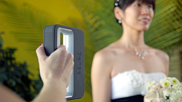
The laser power used for laser scanning of industrial equipment is 1W. The power level is typically 200mW or less.
Construction industry
- Robot control: laser scanner acts as the eye of the robot
- Executive drawings of bridges, industrial plants, monuments
- Documentation of Historic Sites
- Site modeling and layout
- Quality control
- Measurement of works
- Reconstruction of highways
- Marking an existing shape/state to identify structural changes after extreme events - earthquake, ship or truck impact, fire.
- Creation of GIS (Geographic Information System), maps and geomatics
- Scanning of subsurface in mines and karst voids
- Court records
Benefits of 3D scanning
Creating a 3D model by scanning has the following benefits:
- Makes working with complex parts and shapes more efficient
- Encourages product design when needed to add a part created by someone else.

- If CAD models become outdated, 3D scanning will provide an updated version
- Replaces missing or missing parts of
Entertainment
3D scanners are widely used in the entertainment industry to create 3D digital models in film and video games. If the model being created has a counterpart in the real world, then scanning will allow you to create a three-dimensional model much faster than developing the same model through 3D modeling. Quite often, artists first sculpt a physical model, which is then scanned to get a digital equivalent, instead of creating such a model on a computer.
Reverse engineering
Reverse engineering of mechanical components requires a very accurate digital model of the objects to be recreated. This is a good alternative to converting many points of a digital model to a polygon mesh, using a set of NURBS flat and curved surfaces, or, ideally for mechanical components, creating a 3D CAD model.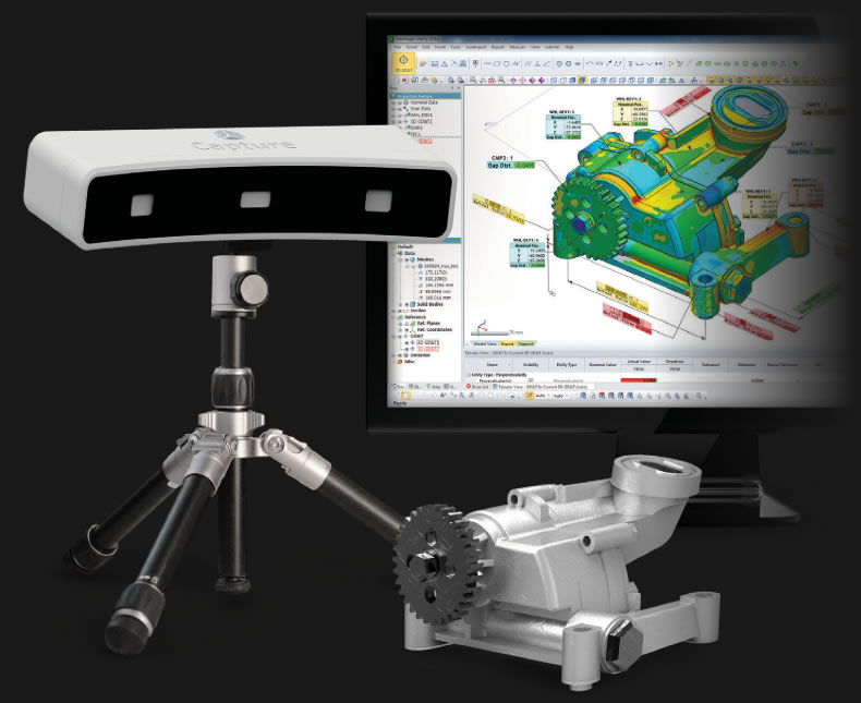 A 3D scanner can be used to digitize objects that freely change shape. As well as the prismatic configuration, for which a coordinate measuring machine is usually used. This will allow you to determine the simple dimensions of the prismatic model. This data is further processed by special programs for reverse engineering.
3D printing
3D scanners are also actively used in the field of 3D printing, as they allow you to create fairly accurate 3D models of various objects and surfaces in a short time, suitable for further refinement and printing. In this area, both contact and non-contact scanning methods are used, both methods have certain advantages.
Cultural heritage
An example of copying a real object through 3D scanning and 3D printing. There are many research projects that have been carried out using the scanning of historical sites and artifacts to document and analyze them. The combined use of 3D scanning and 3D printing makes it possible to replicate real objects without the use of a traditional plaster cast, which in many cases can damage a valuable or delicate cultural heritage artifact. The sculpture of the figure on the left was digitized using a 3D scanner, and the resulting data was converted in the MeshLab program. The resulting digital 3D model was printed using a rapid prototyping machine that allows you to create a real copy of the original object.
Michelangelo
There are many research projects that have been carried out using scanning of historical sites and artifacts to document and analyze them.
In 1999, 2 different research groups started scanning Michelangelo's statues. Stanford University, along with a team led by Mark Levoy, used a conventional laser triangulation scanner built by Cyberware specifically to scan Michelangelo's statues in Florence. In particular, the famous David, "Slaves" and 4 more statues from the Medici chapel.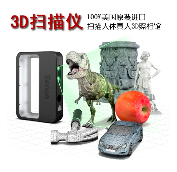 Scanning is performed with a dot density of 0.25 mm, sufficient to see the traces of Michelangelo's chisel. Such a detailed scan involves obtaining a huge amount of data (about 32 gigabytes). It took about 5 months to process them.
Around the same time, a research group from IBM was working, led by H. Raschmeyer and F. Bernardini. They were tasked with scanning the Florentine Pieta sculpture to obtain both geometric data and color information. The digital model obtained from a Stanford University scan was fully used in 2004 to further restore the statue.
Medical applications CAD/CAM
3D scanners are widely used in orthopedics and dentistry to create a 3D patient shape. Gradually, they replace the outdated gypsum technology. CAD/CAM software is used to create prostheses and implants.
Many dentistry uses CAD/CAM as well as 3D scanners to capture the 3D surface of a dentifrice (in vivo or in vitro) in order to create a digital model using CAD or CAM techniques (e.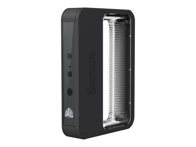 g. , for a CNC milling machine (computer numerical control), as well as a 3D printer). Such systems are designed to facilitate the process of 3D scanning of the drug in vivo with its further modeling (for example, for a crown, filling or inlay).
Quality assurance and industrial metrology
The digitization of real world objects is of great importance in various fields of application. 3D scanning is very actively used in industry to ensure product quality, for example, to measure geometric accuracy. Predominantly all industrial processes such as assembly are quite complex, they are also highly automated and are usually based on CAD (computer-aided design data). The problem is that the same degree of automation is required for quality assurance. A striking example is the automated assembly of modern cars, because they consist of many parts that must match exactly with each other.
Optimum performance levels are guaranteed by quality assurance systems.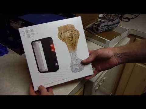 Geometrical metal parts need special checking, because they must be of the correct size, fit together to ensure reliable operation.
In highly automated processes, the results of geometric measurements are transferred to machines that produce the corresponding objects. Due to friction and other mechanical processes, the digital model may differ slightly from the real object. In order to automatically capture and evaluate these deviations, the manufactured parts must be rescanned. For this, 3D scanners are used, which create a reference model with which the received data are compared.
The process of comparing 3D data and CAD model is called CAD comparison, and can be a useful method for determining mold and machine wear, final assembly accuracy, gap analysis, and the volumetric surface of a disassembled part. Currently laser triangulation scanners, structured light devices and contact scanning are the leading technologies used in industrial applications. Contact scanning methods, although they are the slowest, but the most accurate option.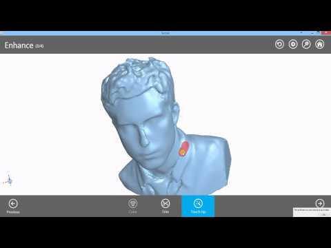
If you have a need for 3D scanning services and / or subsequent reverse engineering, please contact us at [email protected].
Review of 3D scanners for metrological control / Sudo Null IT News Using real examples, we will show the effectiveness of using equipment for solving various problems. After reading the review, it will be easier for you to navigate among a large number of models on the market and determine the criteria for choosing the right device.
Introduction
Every year, the industry produces more advanced devices and devices. Machine parts often have a complex geometric shape, are in close interaction with each other. In order to ensure the smooth operation of the mechanisms, it is necessary to match the shapes, sizes, assembly accuracy and other parameters. Quality control in mechanical engineering was carried out using various technologies, including using coordinate measuring machines (CMMs). However, scanning is by far the most efficient method in terms of the ability to capture data for measurements and the speed of information processing.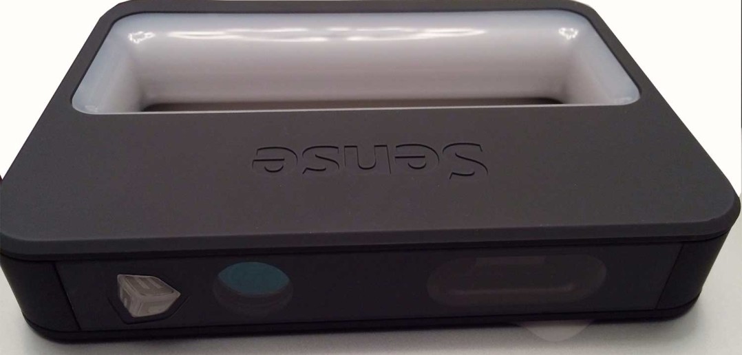
Capabilities of 3D scanners
Source: solutionix.com
3D scanners cope not only with flat surfaces, but also with complex areas: corners between edges and faces, depressions, holes. An important advantage of the devices is the non-contact method of operation, which allows scanning at a distance, in hard-to-reach places.
After the changes are made, the information is transmitted online to a computer, where the software compares the received data and the specified parameters and demonstrates deviations: size mismatches, cracks, signs of deformation and corrosion, and other changes.
Applications
Source: sastrarobotics.com
Digital measurement is a high-tech process that has a number of important advantages over other verification methods. The only disadvantage of the technology is the high price of the equipment. In large industries, with a quick payback, the use of 3D scanners is economically justified. Consider examples:
- large-scale production of parts and devices with mandatory input and output quality inspections;
- small-scale production of objects of complex geometry, impossible without constant quality control.
Situations when other technologies cannot be applied:
- work with objects made of specific materials deformed during the contact method for determining parameters;
- measurement of electronic parts at risk of damage by static electricity;
- re-measurements of objects that are physically absent can also be made on a pre-made digital copy.
Purposes of use
Input control of materials and details is necessary at any enterprise. For large-scale production, selective batches are inspected. However, this requires a large number of controllers, which increases the cost of the product.
The use of 3D scanners automates the workflow, eliminates errors associated with the “human factor”, allows you to switch from selective quality control to continuous, increases the speed of verification several times compared to manual labor.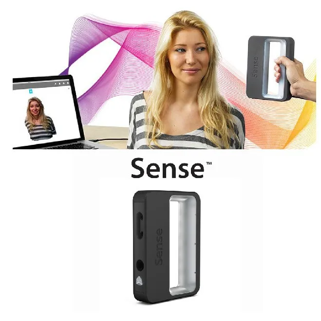
Analysis of the location of parts relative to each other
In a product consisting of several parts, it is important to monitor the correct arrangement of elements in relation to each other. Scanning technology easily captures the position of objects in space and transmits information to a computer monitor.
Checking the geometry of large objects
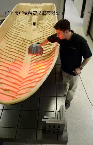
A number of large objects, such as construction equipment, marine and air transport, require regular testing of the hull geometry. The process is lengthy and requires the search for specialists with the necessary qualifications and experience. Metrological 3D scanners easily cope with the digitization of large-sized objects, guarantee high measurement accuracy and save time and financial resources of companies.
Checking the geometry of small objects
Sometimes measuring small objects is more difficult than measuring large ones.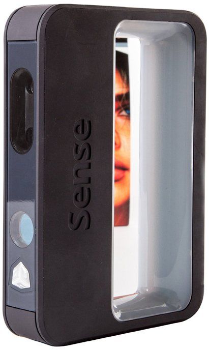 3D scanners successfully measure to within a few microns, regardless of the size of the parts. Deviations of shape and size from the base model are highlighted in the program, which makes it easy to notice and eliminate them.
Selection of equipment
Source: tool-maker.net
There are dozens of models of metrological scanners on the modern digital equipment market. The choice of instrument begins with the identification of the range of tasks set by the production. Here are some parameters that you need to pay attention to and compare with key goals:
1. Working area
It is quite clear that large objects require devices with a large working area. Please note that the size of the working area is in inverse proportion to the resolution. By choosing a device with an excessive scan area, the user may find insufficient accuracy and resolution.
2. Data Accuracy
It is obvious that in aircraft construction and the production of other critical parts, the highest possible accuracy is required.
In reverse engineering of consumer goods, products without complex mechanics, as well as when used in the creation of works of art, souvenirs, in the development of computer games, such accuracy will not be used, for these purposes it makes no sense to overpay for a scanner tens and hundreds of times.
3. Run speed
This parameter includes the calibration and direct scan time. For high-volume production, where 3D scanning is used for quality control, involving dozens of measurements per minute, high speed is an important characteristic. Production of small batches of products and reverse engineering are less demanding on the speed of the device.
4. Software
We recommend giving preference to scanners that work with proprietary highly specialized software. The software required for processing scans, if not included, may require significant additional financial investments.
5. Price
When choosing a 3D scanner, you must independently or with the help of a qualified specialist correlate the tasks of the user and the capabilities of the device. It makes no sense to overpay for unnecessary features. At the same time, it is important that the device has the necessary set of parameters that are guaranteed to give the desired result. It is important to predict the payback period of the equipment.
Examples of 3D scanners for metrological quality control
Let's start our acquaintance with the presentation of the Russian sample - RangeVision Pro. The device is officially approved as a measuring instrument by the Federal Agency for Technical Regulation and Metrology.
Basic information about RangeVision Pro
Source: top3dshop.ru
The device is designed as a universal measuring device for small and large objects with a size of 30 to 1000 mm. Three working zones and a set of interchangeable lenses allow the scanner to accurately digitize jewelry and car body parts.
Measuring accuracy is ensured by structured illumination technology, 6-megapixel cameras and original software solutions.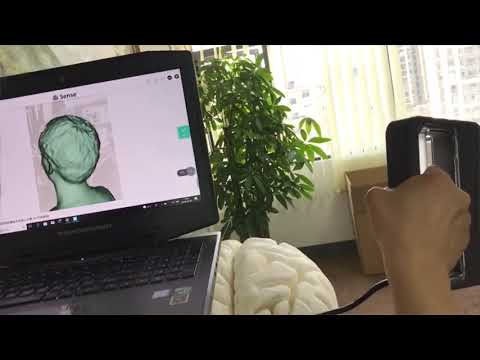
RangeVision software allows you to stitch image elements, fill in empty areas and straighten images. The program includes basic functions for checking the geometry and taking measurements. The output file format is supported by all popular computer-aided design and virtual simulation systems. Software updates are freely available.
RangeVision Pro features
3D scanner application examples in various fields
Dolsatech quality inspection
Source: rangevision.com
whose quality had to be checked. The usual incoming inspection system could not cope with a large flow of products and did not have the ability to test objects of non-standard geometry. RangeVision PRO 3D scanner was used to optimize the process. Current measurement technologies involve the transportation and storage of control samples in specially designated areas. The mobility of the Russian scanner made it possible to reduce logistics costs.
Source: rangevision.com
With the scanner, there was no need to move lots of goods for measurements. RangeVision PRO works in workshops and warehouses - in any convenient place.
In this case, a three-dimensional model of a part with a size of 1700 mm * 720 mm was created. Stickers were pasted onto the part, which made it possible to automatically assemble individual images into a single 3D model. The information was processed by the proprietary ScanCenter software supplied with the scanner.
Quality Inspection at INKAY TECHNOLOGY
Source: rangevision.com
INKAY TECHNOLOGY SRL in Italy had the task of verifying that the dimensions of the body casting matched the base model saved in the CAD file. Given the non-standard geometry of the object, it was decided to abandon the usual technologies and use the RangeVision 3D scanner.
The work was done in 3 stages:
- Scans of the outer part of the body were created using markers for automatic image stitching.
- To scan the inside, the case was divided into 2 parts, each of which was digitized separately.
- Stitched all the images into a single model.
Source: rangevision.com
Quality inspection at the Krasnoye Sormovo plant
Source: rangevision.com
As we mentioned above, 3D scanning is justified not only in high-volume production. Often the equipment is effectively used in the piece production of parts. The shipbuilding industry uses cast components with complex geometry, the quality control of which is difficult and time consuming. Therefore, the use of 3D equipment in the industry is becoming more common.
Krasnoye Sormovo specialists chose RangeVision to inspect the quality of the controllable pitch propeller hub.
Part height - 70 cm, diameter - 80 cm. The RangeVision PRO 3D scanner was moved around the hub, taking pictures from different angles.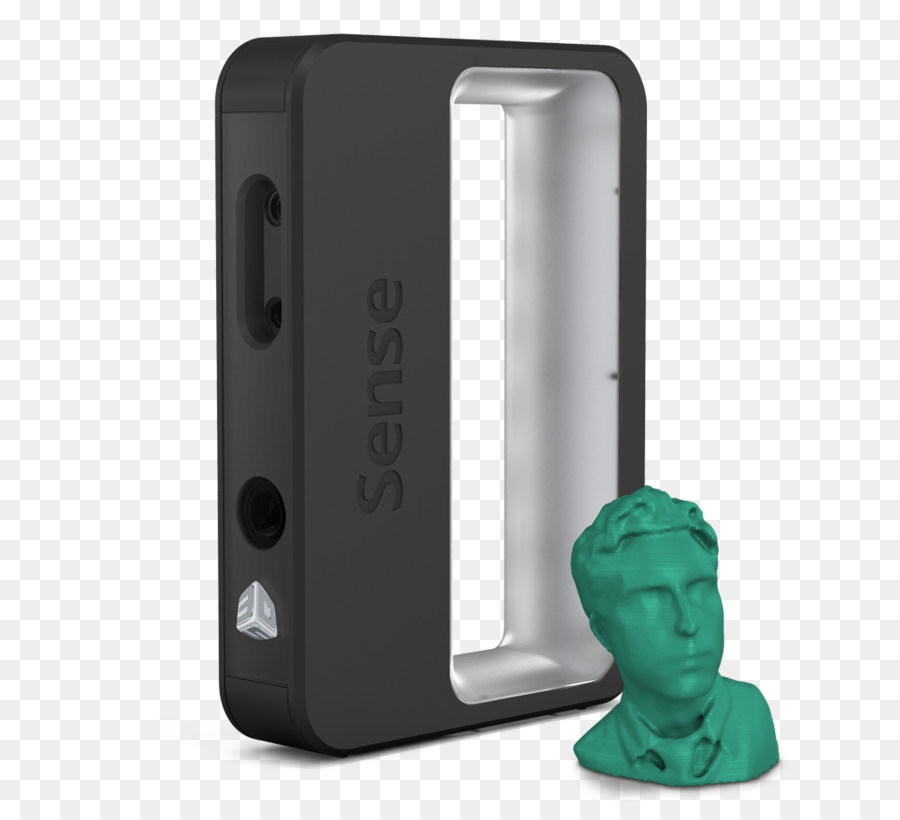 A 3D model was assembled from the 100 images obtained. The stl-file was combined with the basic calculation model in the GOM Inspect software to determine deviations. The work, as a result of which the specialists received an accurate report of the conformity of the finished product to the base model, took several hours.
ScanTech PRINCE775
Source: www.3d-scantech.com
The ScanTech PRINCE 775 portable handheld 3D laser scanner is based on 2 cameras with LED illumination. 2 operating modes are available to users:
- In BLUE mode, the blue laser is active; this mode is used to obtain models of high detail;
- RED mode with red laser is enabled when high sampling rate is a priority.
As a result of scanning, a point cloud is created, which is processed using the ScanTech software solution. The finished image is displayed on the screen of the working device.
Scanner Features
Using PRINCE 775
The main scope of the scanner is the digitization of large-sized objects, such as parts of ships, cars, industrial installations.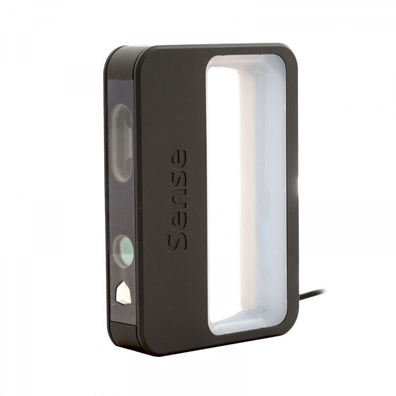 The device can also work with small objects, such as jewelry.
ScanTech PRINCE 775 Applications:
- reverse engineering;
- industrial design;
- quality inspection;
- creation of computer games and 3D movies;
- and in many other areas.
Source: www.3d-scantech.com
An example of using the PRINCE handheld scanner with MSCAN — the use of two instruments increases the efficiency of the process, due to the features of the equipment.
The first device provides high accuracy and detail, the second helps to study large objects using photogrammetry.
Source: www.3d-scantech.com
Digitization of Airbus A350 parts using the kit: MSCAN+ PRINCE. The pair has proven itself in the rapid resolution of quality inspection tasks.
Source: www.3d-scantech.com
Digitization made it possible to create a three-dimensional model of the impeller, since it was impossible to accurately measure it in other ways. 9Creaform HandySCAN Black Elite
The device is suitable for most users, including those who do not have practical skills in working with such equipment. Despite the ease of use, the scanner guarantees high-precision models, even when digitizing large objects of complex geometry.
Scanner specifications
Application area Creaform HandySCAN Black
The device is designed for professional use in various fields. HandySCAN Black excels in tasks such as:
- incoming and outgoing quality control in production;
- reverse engineering;
- pipeline inspection;
- digitization of objects for any purpose.
The scanner is easy to use: all you need to do is connect to your laptop and select a program. During the digitization process, you can pause, examine the intermediate results and continue working.
Creaform MetraScan 750|Elite
Source: industryarena. com
com
Another handheld metrology scanner that produces high accuracy models even for large objects.
Specifications MetraScan 750|Elite
Application area MetraScan 750|Elite
The device is widely used in architecture, energy industry, for reverse engineering and metrological control.
Solutionix C500
Source: psarta.com
The Solutionix C500 is a compact color 3D scanner. The mobile device is placed on any flat surface.
Based on a turntable and two 5MP cameras. The rotation of the platform allows cameras to capture an object from different angles. High speed operation and ease of use provide excellent equipment performance.
Specifications Solutionix C500
Application Solutionix C500
Due to its compact size and the ability to quickly and accurately color scan the device is in demand in many areas, for example:
- in dentistry;
- jewelry industry;
- in education;
- for solving reverse engineering problems in various fields.
Learn more