Roi 3d printing
How to Determine ROI with 3D Printing Equipment
Toggle Nav
Menu
Account
Settings
Currency
USD - US Dollar
- CAD - Canadian Dollar
Posted in: Additive Manufacturing
by Kainon Irons
I work with companies of all sizes to justify the purchase of additive equipment in price ranges from $3K to over $500K. What we have found at Hawk Ridge Systems is that the key to bringing in a new piece of equipment is creating a rock-solid justification for the purchase. At the end of the day, key decision-makers in an organization need to see the value in bringing additive technology in-house. They need to understand the return on investment (ROI). In this post we will review how to do just that by providing a blueprint for creating a strong justification.
Step One: Identifying the Need | Specific Part Files
Identifying the need is a great first step in additive justification. Often, companies are not fully aware of how 3D printed parts can be used within their organization. It is an eye-opening experience to have someone with a little additive know-how walk through a facility and point out numerous examples of potential 3D printed applications. Additive technologies are used in three primary categories: prototyping, manufacturing aides, and production.
The first step to justification is to identify specific part examples in these categories where additive manufacturing may be a good fit. Try and find five to six examples if you can! These can be current projects or past projects. Often, companies will use legacy part files for use in justification because they can directly compare the 3D printed part to what has previously been created using a different manufacturing method.
Sometimes you may not even know if a specific part or project is a good fit for 3D printing. The good news is that we can quickly identify if a part may or may not be a good fit as well as advise on any technical challenges with those tricky part applications.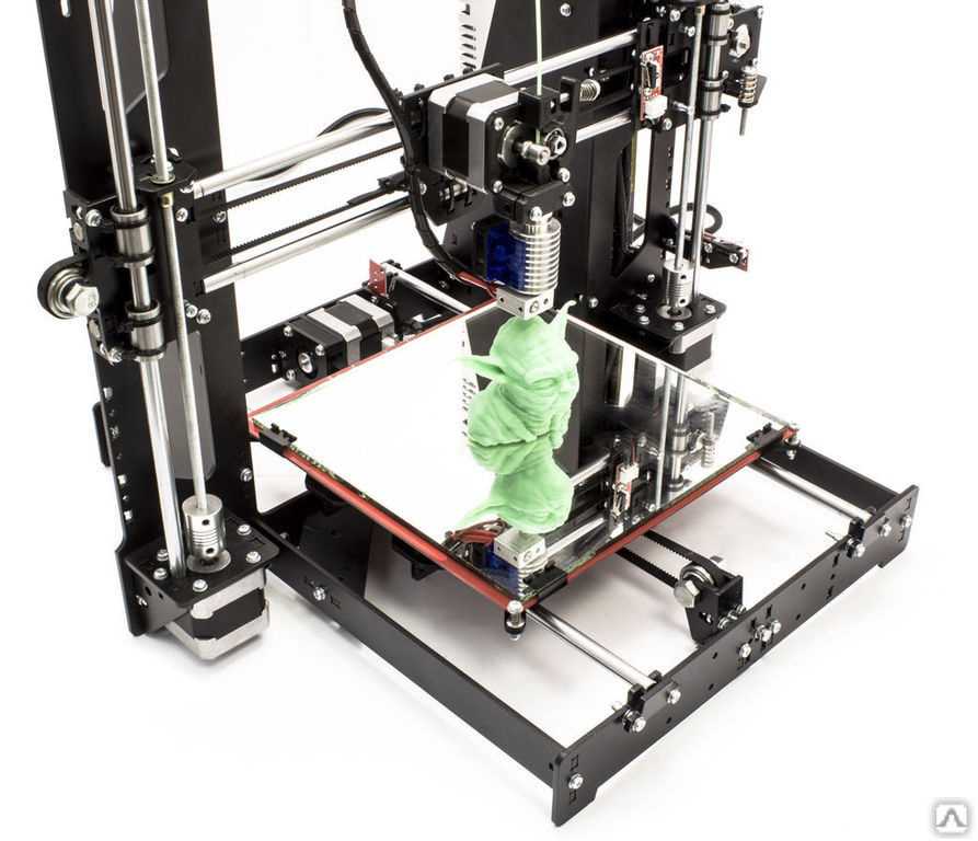
Step Two: Put a Value on Time
I am sure you have heard the statement “Time is Money.” Most would agree with this statement, but putting an actual dollar amount on time can be difficult. Human labor is going to be one of the key time considerations. How many man-hours does it take to produce a specific part using my current process?
The next element to consider is more aimed at production capability of a particular process. What is my current lead time to part in hand? This could be specific to an internal machine output rate, or it could be the lead time from an outside vendor. We talk with folks all the time that move to an additive process to avoid overseas shipping delays for production runs.
Finally, understanding a project time allotment is critical. What is my deadline to produce this part/order? In the highly competitive space of product development, time to market is vitally important. Assigning a value on time to market will go a long way when justifying additive equipment.
Step Three: Understand Your Current Cost
What does it currently cost you to produce this part? This is a critical question in the justification process. In the prototyping world, this could be the cost to outsource the design to a service bureau. For manufacturing aides, it could be a time calculation when an employee and machine must stop working on high-value projects in order to create a jig or fixture. In production, it could be a direct comparison with injection molding for a certain quantity. Lead times, tooling cost, and design changes should be considered in comparison to an additive process that can eliminate some of these challenges.
Step Four: Know your Companies Internal Purchasing Process
Understanding internal budgeting structures as well as how equipment is typically purchased in your company are two key factors in the justification of additive equipment. Is equipment normally purchased using a capital expenditure (CAPEX) or can you make purchases using an operational expenditure (OPEX)? Is your budget determined monthly, quarterly, or yearly? What internal hoops do you need to jump to make a purchase? Who are the stakeholders that need to give the green light to move forward? Having a clear understanding of internal structure will give you a much higher chance of success, especially when it comes to financing options.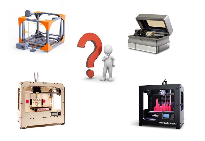 At the end of the day, choosing the path of least resistance is key.
Step Five: Additive Analysis
Now that you have a full understanding of targeted parts, current cost and time, it is now time to compare this data to an additive process. As an Application Engineer, running the numbers is my bread and butter; Hawk Ridge Systems is happy to help!
There are three things to consider when justifying a printing system: true cost of ownership, time, and post-processing. During this analysis, the most effective numbers come from actual part files that have value to your organization.
True Cost of Ownership
Variable Cost
A good place to start in your additive analysis is with the variable costs. Variable costs are purely based on costs related to the production of your part. Typically, variable costs can be boiled down to materials, consumables, and labor. If your part production is $0, then this cost will be $0. A variable cost analysis is one of the best ways to quickly compare an additive process to any other manufacturing method.
Fixed Cost
Once you are satisfied with variable costs, then it is time to dig deeper and understand the fixed cost. Fixed costs are consistent and predictable regardless of how many parts you are producing. This typically involves the price of the machine, auxiliary equipment, service contracts, facilities, and any maintenance kits. Fixed costs can even be amortized over a certain number of years and added into the part cost if desired.
Time
Print Speed / Parts Per Week
Print speed is an important factor to consider when looking at additive technology. How many parts can the system output in a week? Keep in mind your current needs and plan for any future growth in demand for printed parts. Your production requirements and future needs can quickly narrow down the field of additive equipment that will be most suitable.
Human Labor Required to Operate the System
A common mistake that happens when purchasing additive equipment is that the buyer doesn’t have a good grasp of the human labor required to operate the system. If the printing system requires a significant labor investment per part, it is important to capture that time and understand the cost. For those looking to move into production, an important follow-up question is how can this process be automated? For a good example of human labor calculation, check out this video, "Labor Required to Operate the HP 5200 3D Printing System."
Post Processing
Post processing is one of the less glamorous attributes of additive equipment and it is rarely shown in marketing materials by manufacturers. Yet it is key to fully understand what it really takes to have a part in hand. This is true, especially when comparing one additive technology to another. There are two types of post-processing to consider: minimum required post-processing, and further finishing. Often the minimum requirement is related to support removal for most technologies. Powder-based technologies like HP Jet Fusion do not require support structures, yet they do require powder removal through bead blasting. There are also a few DFAM strategies that can be applied to eliminate support structures in extrusion-based equipment such as Markforged. And it is important to understand that all parts do not take the same amount of time to post-process. Some parts have deep recesses or channels that are hard to reach while other geometries are very simple. Make sure you know what it takes for your specific parts.
Further finishing may be required if the raw part is not ready for end-use in your application. This further finishing could be surface smoothing, coatings, machining, etc. Post processing also has a time value, whether that be cleaning, cooling, or drying. In the production world, automated post-processing equipment is strongly recommended. Don’t let post-processing sneak up on you in a justification.
Step Six: Facility Planning
Depending on which machine you go with, facility prep and planning can become a major consideration in the justification for equipment. For larger production printing systems we see two areas that need to be carefully considered: logistics, and print room planning. Logistics include receiving crates and having a clear path for the equipment to reach the print room. In the Bay Area, logistics can be a major roadblock especially with facilities that are multiple stories high. Sometimes facilities do not have large elevators that can handle bigger printing systems. When this occurs the next best option is to bring in a crane and remove an exterior window panel to lift the printing system. To offset this cost, companies will bring in several large pieces of equipment at the same time using this method. In the print room, your major considerations will be power, proper clearance for the machine/auxiliary equipment, and depending on the machine, compressed air and air ventilation could come into play.
We at Hawk Ridge Systems are happy to walk you through every step as we install printing systems in all sorts of challenging environments.
Step Seven: ROI Running the Numbers
Now that you have all of the data, it is time to crunch the numbers. The beauty of this process is that concrete data points gathered from previous steps take away any guesswork. You will have a clear answer at the end which is great! If equations make your palms sweaty, no worries! Just take a look at what should be considered and we can help with the math. We love crunching numbers and would be happy to help you out at this stage.
Variable Cost Savings
Start by gathering variable cost savings. This is done by subtracting your current part cost from the additive part cost. Remember, variable costs do not take into account the cost of purchasing the machine. We are only looking at materials/consumables and labor at this point. Variable cost savings calculations will act as a sanity check, you normally want to have a lower additive part cost compared to traditional manufacturing at this point. If not, make sure and capture the additional savings in the next step to see if additive is going to be a good fit.
Additional Savings
Next, it is time to capture additional savings gained from switching to an additive process. These amazing benefits are often overlooked in a cost analysis. It is very important to understand these benefits by putting a dollar amount on them.
Time Savings Example: Your current lead time for an order of 100 parts could be two months, but an additive process can bring that lead time down to one month for 100 parts. What is the value of this per part? Time Savings (per part) = Dollars Saved Per Month from Faster Lead Time / Number of Additive Parts Produced Per Month
Engineering Design Savings Example: You now have more freedom to design parts without traditional manufacturing constraints. This leads to quicker designs and/or savings from outsourcing the engineering work to a manufacturing engineer. Engineering Design Savings (per part) = Engineering Labor Savings / Total Number of Parts Desired
Increased Profit from Increased Production Example: You determine that an additive process will allow you to produce and sell 100 more products per month. Your profit per part is $20. You now make $2,000 extra per month by switching to additive. Increased Profit from Increased Production (per part) = ((Additive Parts Per Month – Current Parts Per Month) x Profit Per Part) / (Additive Parts Per Month)
Tooling Savings for Revision Changes: Your product is normally injection molded but you incur high tooling costs for design changes, now you want to look at an additive solution to allow for free revision changes. You typically go through two revisions during a product life cycle and each revision will cost $15,000 (not including the original cost for the tool since this is captured in the original part cost comparison). Tooling Savings for Revision Changes (per part) = (Number of Revision Changes x Tooling Cost) / (Total Number of Parts Desired * (Number of Revision Changes/(Number of Revision Changes + 1)))
Total Savings
Total Savings is simply adding the variable cost savings to additional savings to provide a complete picture of what should be considered in the ROI calculation. At this point, you will have a good idea if an additive solution is right for you.
ROI Break-Even Point
Lastly, it is time to determine how many years it will take to break even with a particular machine. To do this you will multiply your total savings calculated from the previous step by the number of parts a particular machine can produce in a year. Then divide that number by your fixed costs. This is your total cost of equipment including auxiliary equipment and any maintenance plans or warranties.
ROI Break-Even Point Example: Your total cost of equipment is $250,000. You determined that you can save $50 per part with an additive process and can produce 2,000 parts per year. Your break-even point is ~2.5 years. After that, you are in the green!
Step Eight: Plan for Future Growth
Will your additive solution be scalable for higher demands and future growth? It can take a great deal of effort to have a piece of equipment approved for purchase. Make sure that the machine you bring in will not only address your current needs but future needs as well. Once the word is spread that you have a new machine, will other groups within your company all of the sudden start having print requests? Do you have future projects in the pipeline that can heavily use additive manufacturing? Does your facility layout lend itself to future expansion? These types of questions are good to consider when planning for the future. Thinking forward to the next 5-10 years can pay off nicely when you have a scalable solution in-house.
Step Nine: Understand the Purchasing Options
Now that you know additive is the way to go, it is time to look at purchasing options. When looking at a large purchase, many routes can be taken. Leasing, financing, or outright purchasing the equipment are all very common purchasing routes. Often we see customers who take advantage of specific pricing, or payment plans who are now able to jump up to a larger machine that better suits their needs. This is especially true when the purchase can be moved to OPEX. Having a lower monthly payment can be much easier to swallow rather than a big chunk all at the same time. Hawk Ridge Systems has great financing partners who are familiar with additive equipment and knowledgeable in this industry. We are happy to help you navigate the purchasing process.
There you have it, by following this tried and true blueprint you will be well prepared to create a rock-solid justification for purchase with your next 3D printing system. If you are ready to start your justification process, feel free to contact us at Hawk Ridge Systems today!
December 30, 2021
Did you like this post?
Related posts
Related Products
Comments
Please login to comment.
Don't have an account?
Sign Up for free
Recent posts
Email address is required to login
Calculating Cost Savings for Metal 3D Printers with Examples
Learn Blog
While metal 3D printing carries incredible hype, the most important factor in determining whether or not to purchase one is its potential value-add to your business. In this section, we’ll show how to measure the financial returns of metal 3D printers over time, and calculate the investment's payback period.
How to Calculate Financial Returns and Payback Period
Calculating returns over time will tell you approximately how long it will take for a new machine to create enough value to offset its acquisition costs.
First, start with acquisition costs. These include:
1. The purchase price of the machine.
2. Facility upgrades.
3. Cost of machine shipment and installation.
4. Cost to warranty and maintain the machine, plus replace parts, as needed.
5. Cost to train your workers, which is separate from fixed costs but important.
Depending on your unique facility needs and the type of printer you choose, acquiring a metal printer can cost anywhere from $150,000 to more than $1 million.
Next, calculate an average operating cost savings per unit time. This should be measured against your current process and adjusted/averaged over time. Use these steps to start.
6. Pick a part that represents what you would commonly print with the machine.
7. Determine cost per part by getting a part quote from a 3D printer OEM.
8. Estimate the cost to produce the same part with your traditional methods at your typical manufacturing volume.
9. Calculate cost savings per unit time by subtracting the printing cost from fabrication cost with a standard method. Divide that number by fabrication time.
10. Now, take the overall machine cost and divide it by the cost savings per unit time we found in step
4. The number you get will be the amount of time it takes to pay for the new metal 3D printing machine.
Example: Direct Financial Returns (Shukla Medical)
Shukla Medical predicted that a Markforged Metal X would pay for itself in less than two years if they used it to in-source prototyping operations.![]()
- Acquisition Costs: All in, the Markforged Metal X system cost Shukla between $150k and $175k. This included the full system, installation, warranty, and small facility changes.
- Cost Savings: By replacing their overseas prototyping operation with parts printed on their Markforged machine, they calculated they could save around $1,000/prototype at a volume of about 10 per month. Based on this, they believed the monthly savings would be about $10k/month.
- Breakeven time: Based on costs and savings accrued over the first year of owning their machine, Shukla is on track to break even on their investment in about 18 months. Their calculations have proven accurate, and they’ve found other ways to generate value with their printer.
“
We either would send it out of house to a third-party vendor or Protolabs or just another machine shop, and that’s fine, except it’s usually pretty expensive — high machine costs drove us to get a Metal X.” -Zach Sweitzer, Product Development Manager, Shukla Medical
–
Indirect Returns
Calculating financial returns will give you a bulletproof case for acquiring a metal 3D printer. However, the returns based on part costs only tells part of the story. Leveraging in-house printing of 3D printed metal parts can benefit your organization in a wide variety of tangible ways.
Value can go beyond financial investments.
Additional benefits that extend beyond traditional cost- and time-value calculations include:
- Decreasing part lead times: In addition to decreasing part cost, 3D printing also delivers parts at much shorter lead times. This can speed iteration, get products to market faster, and increase uptime.
- Decreasing labor to make parts: Some 3D printers require much less labor than conventional machines.
 Save CAM programming time, operator time, and engineering drawing time (for parts that do not need drawings for tolerances) by printing parts.
 - In-sourcing parts gives you more control: Outsourcing saves labor, but can introduce uncertainty into a fabrication process. Bringing fabrication in house gives you control.
- New fabrication capability: 3D printing parts can enable higher-performing designs and new parts that can’t be made traditionally.
Brainstorm the ways you might use metal 3D printing to solve those problems that you can’t easily assign a financial benefit. Then, add it to your demonstrated financial returns from the previous page.
Example: Indirect returns (Shukla Medical)
In addition to building a strong financial case to invest in metal 3D printing technologies, Shukla found acquiring a machine allowed their R&D department to run more efficiently.
Decreased Lead Times: Faster lead times allowed Shukla engineers get their products in the hands of surgeons faster, iterate more, and deliver products to market faster.
In Sourcing: Bringing fabrication in-house allows Shukla greater control over what’s getting made when, as well as greater freedom to explore new parts and make one-offs.
“
Being able to prototype more efficiently and get finished products to market more quickly will keep us on the forefront of the industry.” - Zach Sweitzer, Product Development Manager, Shukla Medical
–
Learn Blog
Shukla Medical: Using 3D Printing to Get Tools in Surgeon's Hands Faster
Learn how Shukla Medical reduces time in the operating room with 3D printing
All of the blogs and the information contained within those blogs are copyright by Markforged, Inc. and may not be copied, modified, or adopted in any way without our written permission. Our blogs may contain our service marks or trademarks, as well as of those our affiliates. Your use of our blogs does not constitute any right or license for you to use our service marks or trademarks without our prior permission. Markforged Information provided in our blogs should not be considered professional advice. We are under no obligation to update or revise blogs based on new information, subsequent events, or otherwise.
Never miss an article
Subscribe to get new Markforged content in your inbox
required required requiredSubmit
Threads in 3D printing
Dear friends, welcome!
This article would like to highlight the appearance of threads in printing. I will try to note the main factors influencing the appearance of threads.
1) Idling speed and acceleration. The idle run consists of the following stages - first there is a retract, then the movement of the extruder, then again a retract. The plastic is spontaneously squeezed out precisely during the idle time, forming various kinds of defects. Now imagine an example if the idling takes zero seconds. Under this condition, the plastic will not have time to spontaneously extrude. Therefore, the higher the speed and acceleration, the less time the idling lasts, which means there will be fewer threads. But speed and acceleration are limited by the motor driver, the motors themselves, and the rigidity of the printer frame.
Therefore, you can try to slightly increase the speed and acceleration with each print, but at the same time make sure that the motors do not overheat, otherwise microsteps may be skipped, which will lead to print rejects.
2) Idling path. Different slicers process parts according to different algorithms, which means that the idling trajectory may differ. Some slicers build more rational extruder motion than others. Therefore, you can try to prepare the same part in several slicers and stop at the option that will be more rational.
3) Feeder dependent, i.e. from the plastic supply system. Printers most often have one of two options: "bowden", i.e. far-distance or "direct", this is when the "feeder" is located near the extruder. Under the same printing conditions with direct, there will always be fewer threads than with bowden. But this does not mean that you can always switch from Bowden to Direct. It may also be that your printer will not be able to work with "direct" for one reason or another. The transition to "direct" must be considered with each printer individually.
4) Retract setting, i.e. plastic rollback - its task is to remove the residual pressure in the extruder during idling. Without retract, the threads will appear more intensely. For most printers, the values are as follows - for direct, the range is from 1 to 6mm, and for bowden, from 4 to 12mm. (the amount of retract also depends on the diameter of the nozzle).
5) Plastic quality. If you are constantly printing only budget plastics and are unhappy with the result, then try to buy plastic in a higher price category, and more importantly, with good reviews. And then compare the print quality. But the main thing - from different manufacturers, compare the same types of plastic - you should not compare, for example, ABS from one manufacturer, and PLA from another.
6) Plastic drying. By the way, this applies to almost all plastics, not just nylon. If you have unnamed or cheap plastic in your hands, it is recommended to dry it after opening it, because. it is not known whether the plastic was dried before packaging.
7) Nozzle diameter. The larger the diameter, the more plastic will spontaneously squeeze out during idling. There is nothing you can do about it, it just needs to be taken into account when choosing a nozzle diameter.
8) Extruder temperature. If you heat the extruder to the upper limit of the recommended range (indicated on the plastic that is being printed), then the fluidity of the plastic will be higher, and it will be more easily extruded from the nozzle. Plastic manufacturers give a temperature range for a reason. If you set the print speed to high, then the extruder temperature should be in the upper limit of the range. But if the print speed is low, then there is no need to heat up the extruder much, otherwise filaments may appear due to overheating of the plastic.
Therefore, you can try to reduce the temperature of the extruder as follows - during printing, every couple of minutes, reduce the temperature by 5 degrees over and over and watch the print closely. If the threads disappear, remember the temperature and stick to it. But if the temperature is greatly lowered, then the plastic will not be able to extrude at all. Don't overdo it.
9) Dependence of temperature on the type of extruder. There are many different models of extruders. For example, consider the E3D V6 and E3D V6 Volcano extruder. The E3D V6 Volcano has an extended nozzle and an extended aluminum block. And this means that the zone where the plastic is in the molten state is larger, so it can push through a larger volume of plastic per unit of time. As a result, this extruder will be able to print at higher speeds than the regular E3D V6. But here you need to understand the following - if you have a "powerful" extruder, and you print at low speeds, then the plastic will overheat, which will lead to the appearance of threads. Therefore, for powerful extruders, it is better to set the temperature in the lower limit of the recommended range. And on the contrary - for an extruder that cannot heat up a large amount of plastic, the temperature should be kept in the middle or at the upper limit of the recommended one.
The conclusion here is the following - for different models of extruders, different printing temperatures are needed.
10) Free travel distance. If you are printing multiple parts at once, try to space them closely to reduce the dry travel distance. Well, if a solid part is printed, with individual elements at a great distance from each other, in this case, you can try to change the location of the part in space so that there are fewer idle moves.
11) File analysis before printing. When your G-code is ready, do not be lazy and meticulously analyze it before printing, because. at the verification stage, you can detect unwanted elements that can create various kinds of defects, including the appearance of threads. By the way, in whatever slicer I prepare the file, I almost always check the finished code with the help of “Repetier-Host”, because it shows all the movements that can lead to certain defects.
12) Plastic type. All plastics have both strengths and weaknesses. For example, PETG plastic has a high tendency to filament. ABS, on the other hand, has a low predisposition to threads, but it will have to concentrate on the problem of shrinkage and a low degree of sintering of the layers.
Therefore, before printing, familiarize yourself with the pros and cons of the plastic with which you plan to print.
13) Using the "Lift Z" function. When enabled, a gap will be created between the extruder and the printed part. It is needed so that during idle the extruder does not cling to the outer walls of the part. This feature can significantly reduce the number of threads. But it should be used if the printer has a powerful driver and a motor along the Z axis, as well as a screw with a thread pitch of at least 8mm. This is necessary to achieve high speed and acceleration on the Z axis. Well, if you try to use this function at low speeds, the problem will only get worse and there will be more threads, because. idle time, taking into account "Lift Z", will increase greatly. The idling time with the "Lift Z" function consists of: movement along the Z axis + retraction + idling + retract + movement along the Z axis.
Therefore, you can try to experiment with this function and see the result.
14) Problems with the extruder. Imagine a situation where you put a large retract, but a large plug of melted plastic formed in the thermal barrier between the nozzle and the Teflon tube. In such a situation, no matter how big you put the retract, this plug will not disappear, but will remain in its place. And, therefore, the retract will not be able to completely relieve the pressure in the system. Therefore, keep your extruder clean and in good working order.
15) Problem with the driver on the motor in the feed system (motor on the feeder). It's a rare phenomenon, but it's still there. I've run into a problem where the driver only spins the motor in one direction, regardless of the command, whether it's spinning one way or the other -- the motor only spins in one direction.
And in practice it looks like this: the motor advances the plastic during printing, and at the moment of idling, when a retraction should occur, the motor sharply squeezes out additional plastic (because the driver rotates the motor in only one direction).
As a result, although this phenomenon is rare, it still took place in my practice.
Thank you for your attention, I hope the material was useful, I wish you all the best!
3D printing in plastics, basic parameters
Plastics such as ABS and PLA have long been and will continue to be the most popular materials for 3D printing for a long time. The main reason is their affordability in conjunction with relatively high strength characteristics compared to other materials. In this article, we will not delve into the reasons for the popularity of the plastics described above, fully describe their characteristics, or delve into the features of 3D printing technology. Here we want to highlight the effect of print settings/parameters and the position of the part on the printing platform, when printing with FDM (FFF) technology, on the final strength of the product.
You can learn about how a 3D printer works here, about 3D printing technologies (including FFF, FDM) and how they differ here.
The strength characteristics of a 3D model can be affected by 3 main factors: layer thickness, filling and orientation of the model relative to the printing platform.
Layer Thickness
Layer Thickness is an adjustable parameter that determines how much vertically (Z-axis) the furnace head moves when moving to the next 3d layer. There are 4 standard sizes: 0.1, 0.15, 0.2 and 0.3 mm. There are smaller values, but, frankly, with a standard 0.4 mm nozzle, they make no sense (there will be no noticeable difference in quality). There are larger sizes, but they require a larger diameter nozzle. The typical value for this parameter with a typical 0.4 mm nozzle is 0.2 mm (200 microns).
First of all, it is worth mentioning that the layer thickness directly affects the surface quality (this is especially noticeable on surfaces slightly deviated from the horizontal or vertical), the lower the layer height, the higher the surface quality. This of course will depend on the type of printer, speed settings, etc., but we will not go into this. The higher the layer thickness, the correspondingly lower surface quality, while a simple transition from 0.2 to 0.3 mm will be noticeable.
Next, it is worth mentioning that the higher the layer height, the faster the printing and, accordingly, the less it costs. So 0.1 from 0.2 differs in speed by 2 times and in cost by 1.5-1.7 times.
Finally, strength. Without going into technical justifications, let's just say that the greater the thickness of the layer, the greater the overall strength of the product.
Infill
Infill in 3D printing with plastic is a configurable parameter that controls the amount of material and voids inside the outline of the model.
The outline of the model (default 1.2 mm) is the wall separating the outer space from the interior of the model. Since the printable models have a closed volume, when the print is finished, the interior space is completely hidden.
By default, the parameter is set to 12.5% (12.5% - material, 87.5% - void), creating the required minimum strength. The higher the infill, the greater the weight and printing time of the model, and, accordingly, the cost.
For printing on plastics, you can choose any infill from 10 to 100%. It is better not to choose more than 90% to keep the minimum headroom for depreciation. Many tests have proven that 90% filling is stronger than 100%. The presence of free space inside adds additional strength under dynamic loads and object operation in changing conditions (for example, cooling-heating), due to the ability of the material to absorb into empty space. Moreover, 100% filling has a negative effect on the quality of the surface: small excesses appear on it plastic.
The relationship between filling and strength is simple: the higher the filling, the higher the strength. It is also worth remembering: the higher the filling, the greater the cost.
Location of the part on the printing platform
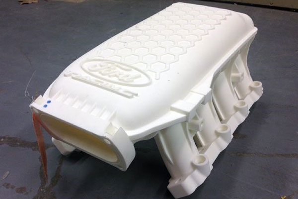
The location of the part on the working platform is controlled by the 3D printer operator and can significantly affect both the strength and the quality of the surface of certain areas. In some cases, this parameter is unregulated, since the very shape of the model dictates the only correct location. For example, a thin plane with a small relief on one side (a plate with letters) should not lie on a plane (and not stand on an edge) so that the letters are directed upwards.
One can probably write a separate article about the location of the part, since the quality of the surface from different sides will largely depend on the shape of the model and the presence / absence of support. To do this, you need to understand the principle of operation of the FDM (FFF) technology, you can find it here.
Effect of location on strength. For example, let's take a 10/10/1 cm parallelepiped. When printing "lying down" (the 10/10 cm plane is placed on the platform), the layers are located along the main plane. When printing "on edge" (plane 10/1 cm), the layers are arranged across the main plane. The strength of the model across the main plane will differ up to 6 times.