Delta 3d printer dimensions
Delta geometry - RepRap
Contents
- 1 Introduction
- 2 Geometry of a linear delta
- 2.1 Schematics
- 2.2 Reachable area
- 2.3 Delta columns and axis names
- 2.4 Effector stability
- 2.4.1 What is effector stability ?
- 2.4.2 How to improve geometry
- 2.4.3 Position of the hotend
- 2.4.4 Quantifying the effects of the geometrical stability: TES coefficient
- 2.4.5 Implementation
- 3 Interactive web simulation
- 3.1 Linear deltas
- 3.2 Rotational deltas
- 4 Simulation on software
- 5 Delta calculators
- 5.1 Linear deltas
- 5.2 Rotational deltas
- 6 Math and research papers
- 7 Calculation links
- 8 Simulation without source/access
- 9 Calibration
Introduction
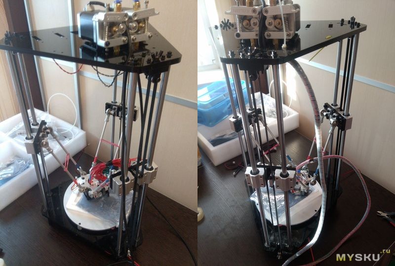
A 'delta' robot or printer is a robot where a platform is maintained by three pair of arms set in a triangle. The pairs of parallel arms maintain the horizontality of the platform and the movement of these arms displace the platform in the three dimensions. Many solutions exists, but a few are used practically.
There are two principles to displace the arms pairs:
- Each arm pair is installed on a main articulated arm, the movement being generated be the rotation of this main arm. The geometry is the rotational delta or 'Clavel delta' from the name of its inventor. The principle is widely used on 'pick and place' machine in a wide range of industries, from electronic to food. This system can be found in the Delta by Energetic or on the FirePick Delta printers.
- Arm pairs are attached to carriage sliding along parallel rails. This geometry is called linear delta and is the most frequent type used in 3D printer world, the machines originating the movement being the Rostock and the Kossel. The term 'parallel delta' shall not be used as all robots with parallel arms are called parallel robots.
There is another solution without rigid mechanics which is to suspend the platform to wires. There are a few examples and notably the Skydelta or this suspended delta
The linear delta kinematic calculation is simple because the carriage follow a straight line, so the horizontal movement of the platform is linked to the vertical movement of the carriage by Pythagorean theorem (which states that the diagonal length squared, is equal to the sum of the triangles sides squared, the triangle must be a right angle triangle). Here the diagonal is the arm length, constant, the vertical branch is the relative vertical position of the platform and carriage, the horizontal branch is the relative horizontal position of the platform and carriage.
The math is not difficult, but for a printer a lot of square roots must be done. Control boards based on 8 bit processors are struggling doing these calculations so a lot of fine software optimization were done for the delta geometry for these processors.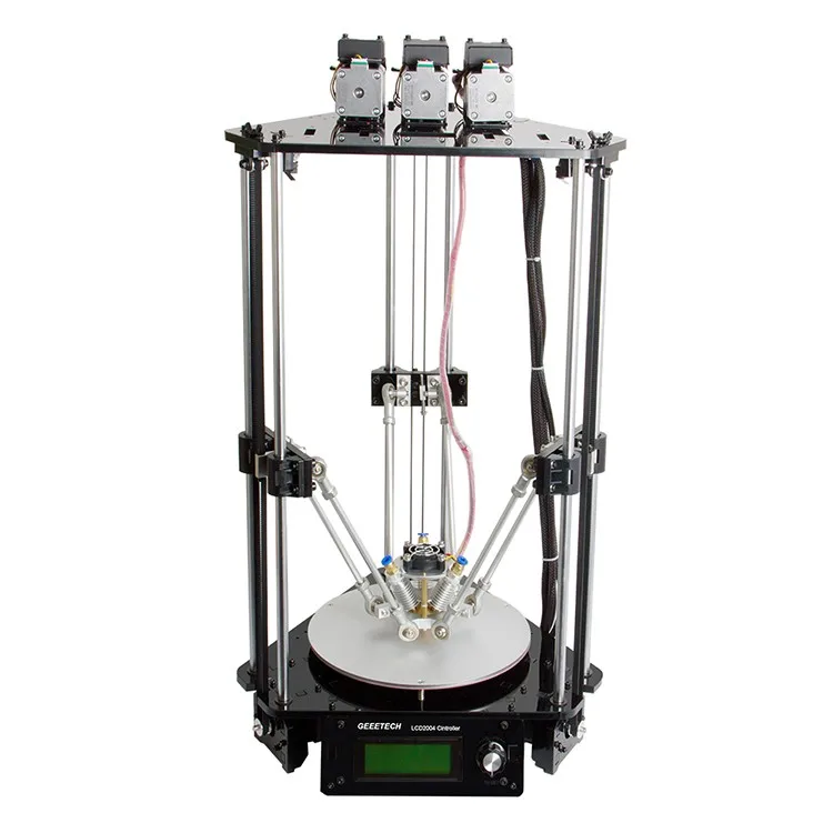 32 bit controllers are becoming the controller boards of choice more commonly for delta printers as they have much faster processors and do not struggle with the math at all. It shall be noted that the three sliders columns can be on positioned on a non-equilateral triangle and asymmetric dispositions were tested, notably the 'Square' delta with angles of 90°,90° and 180°.
Geometry of a linear delta
Schematics
The arm angle with effector at center is the result of the arms length, minimum angle and angles of the arms while at maximum diameter. For minimum angle of 20°, this angle is around 60° for maximum diameter arm verticals, but if the minimum angle is increased, it may be higher. Minimum angles of 22° will gives an angle of 63° with vertical arms.
Arms may not be able to reach the vertical due to clearance problem, notably with the part cooling fans or effector accessories. In that case, for a given minimum angle, arm length may be reduced and the angle while effector is at center will be lower.
On the other way, some printers have arms capable to go over vertical (e.g. Rostock Max).
The minimum arm angle, while effector is at maximum diameter, is one of the basic design parameters. It is important for effector stability, precision and carriage speed. A low angle induce high carriage speed for a given effector horizontal speed. Low angle also decrease effector stability. Generally, 20° angle is considered as a practical minimum and induce a carriage speed 2.75 times higher than effector horizontal speed. Some printers with theoretical minimum angle of 15° may experience lost steps at their maximum diameter.
Speed up coefficient for given arm angle
| mini angle | speed multiplier |
| 22.5° | 2.41 |
| 20° | 2.75 |
| 17.5° | 3.17 |
| 15° | 3.73 |
| 12.5° | 4.51 |
Arm space does not influence movement calculation, but have an importance for the effector stability. Best stability is obtained for the minimum offset, with the maximum possible arm space for this offset (minimising b dimension).
Reachable area
For a given minimum angle, the reachable area is a triangle with bulged sides, with the ends of the triangle oriented toward the columns, which cannot be accessed without impacting the column. Then, for simplicity, the reachable area is generally considered circular. It might be interesting to evaluate the real reachable area when one want to inscribe a rectangle or square in the printing area. The accessories (belts and fans) are critical for the real usable area.
Schematic
- Green : the area which may be reachable without obstacle
- Orange : the practical area taking into account the clearance required between effector and columns.
Delta columns and axis names
View from top
Effector stability
What is effector stability ?
This is the fact that an effector resist to tilting moments. The tilt may displace the hotend nozzle and creates imprecision. It also have an effect on level measurement sensor while the sensors are offset from the hotend. Two things have important effect on an effector stability:
- The geometry, as different geometries may induce higher or lower loads on arms and articulation, so higher or lower deformation. A geometry reducing the load will increase precision.
- The moment resistance induced by arm articulation, say a cardan will resist to torsion induced by the effector, while ball articulation will not.
The moment which will induce tilt will be created by :
- Inertia
- Load on the nozzle
- Friction in articulation, which may be significant for some types of articulations.
How to improve geometry
- A small offset will reduce the load on arms/articulation for a moment and shall be researched.
- For a given offset, the distance between the centers of articulation (noted 'b' on drawing) will modify the moment created by side loads.
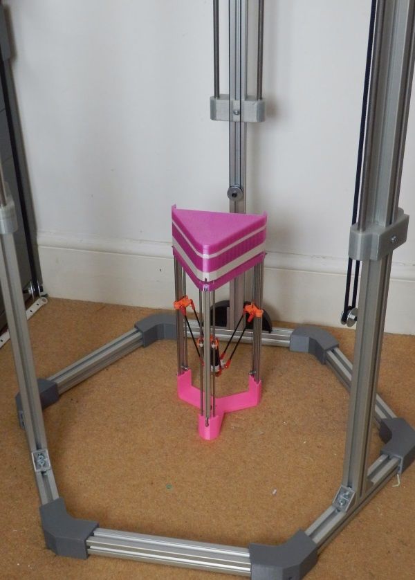
 The lower this space, the better the stability. When these articulation are merged, the geometric stability is very important, as there is no possible level difference in the merged articulations, hence, no possibility to have an 'articulated' tilt. This solution is used by example on the Spiderbot delta.
Position of the hotend
What is also very important is the position of the hotend to minimize the effect of effector tilt. Experience show that a nozzle near the effector plane seems the best solution. However, care shall be taken to limit the raise of the center of gravity, to avoid creating dynamic moments.
Quantifying the effects of the geometrical stability: TES coefficient
Understanding that there are other causes that the effector stability to nozzle movement imprecision, it is however interesting to quantify the displacement due to geometrical instability.
A coefficient could be defined, that we may called TES, for tilt effector stability, which will not quantify the effector instability, but its effect on the hotend, by combining the moment effect and the displacement related to the distance between the virtual articulation and the nozzle location.
a being the lever due to arm space (see drawing) b being the space between balls (articulations)
- Tilt geometric load moment is related to a/b, a being proportional to arm space
- Tilt stiffness is proportional to arm space
TES = (Arm space)²/b, Dimension units shall be mm.
It is important to note that the TES does not depend from arm length, only effector geometry. Indeed, the arm stiffness in their axis is huge compared to other elements, notably articulation stiffness, so the arm length have nearly no effect on tilting stability. This is why you could install the small Kossel mini effectors on large printers without problems. It shall be noted that for merged articulations, this coefficient will be infinite.
This coefficient is calculated in the OpenScad delta simulator.
Implementation
The practical improvements added by a good geometry is closely related to the quality of the mechanical implementation. By example, if you widen the arm space to improve stability, but the side extensions on the carriage to reach the new width add excessive flexibility, you may have at the end reduced the real stability.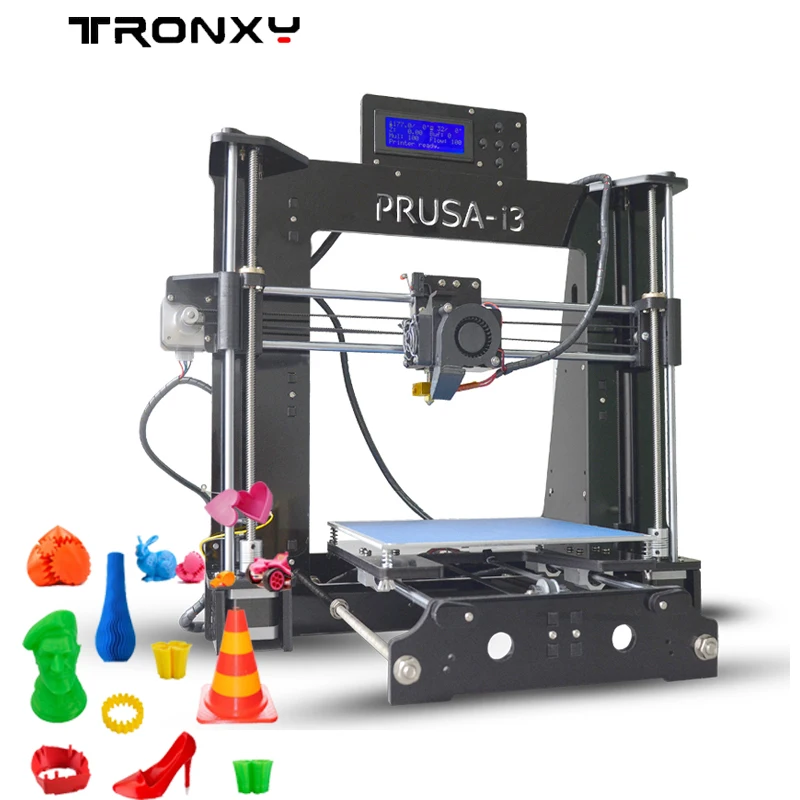 It shall be noted that wider arm space does not raise or decrease the moment and only help to fight play in articulation. If your problem is the rotation of the carriage, that is the carriage which shall be reinforced, no geometry can help.
Interactive web simulation
Linear deltas
- GeoGebra dSim graphic simulator for linear delta, use sliders to adjust parameters. Can be viewed in 3D with red/blue glasses.
- Thinkyhead Deltabot calculator for linear delta, enter numbers for simulation.
Rotational deltas
- Parola Java based simulator, rotational delta with many options
- http://arvc.umh.es/label/delta.html
Simulation on software
- OpenScad delta simulator for linear delta with active simulation, with common printers datasets predefined. Change variables values for simulation. You can see a film here or here (Fisher Delta)
Delta calculators
Linear deltas
- http://www.
 heliumfrog.com/deltarobot/details/details.html Excel sheet calculator for linear delta
 - https://github.com/Jaydmdigital/mk_visual_calc OpenScad calculator with visualization dedicated to Kossel
Rotational deltas
- marginally clever Online calculator
- Trossen robotics forum
Math and research papers
- File:Rostock Delta Kinematics 3.pdf Comprehensive paper of Steve Graves about linear delta kinematics
- https://groups.google.com/forum/#!topic/deltabot/V6ATBdT43eU Deltabot forum thread on Steve Graves paper with other useful resources
- http://robinsonia.com/wp/?p=161 math explanations for linear delta
- http://scholar.rose-hulman.edu/cgi/viewcontent.cgi?article=1000&context=mechanical_engineering_grad_theses Linear delta research paper, but with the sliders parallel to the effector plan.
Rotational delta are a quite common research topic, notably for university students.
- http://www.
 ohio.edu/people/williar4/html/pdf/DeltaKin.pdf Rotational delta kinematics.
Calculation links
- https://hackaday.io/project/963-firepick-delta-the-open-source-microfactory/log/3588-6152014-delta-mechanism-simulation-and-accuracy-determination (Rotational delta)
Simulation without source/access
Some people have done Delta simulation on CAD/Math software, but not publicly release them.
- https://www.youtube.com/watch?v=8_6QfZ6DJfU film of a Simulation with Matlab
- https://www.youtube.com/watch?v=K2zxvHq3iC8 film
- https://www.youtube.com/watch?v=OwI6hYHWbjw A python simulator, undisclosed program.
Calibration
- http://forums.reprap.org/read.php?178,639039 Arm length calculation from printing part
- http://escher3d.com/pages/wizards/wizarddelta.php web calculator for calibration parameters
- http://forum.seemecnc.com/viewtopic.php?f=36&t=8698 calculator for calibration parameters
- https://github.
 com/hercek/Marlin/blob/Marlin_v1/calibration.wxm Calibration calculator running with WxMaxima
 - http://forum.seemecnc.com/viewtopic.php?f=82&t=7640 forum thread about Heuristic calibration algorithm
In addition to site licence GFDL1.2, this page is also released under license CC BY-SA 4.0
Delta geometry - RepRap
Contents
- 1 Introduction
- 2 Geometry of a linear delta
- 2.1 Schematics
- 2.2 Reachable area
- 2.3 Delta columns and axis names
- 2.4 Effector stability
- 2.4.1 What is effector stability ?
- 2.4.2 How to improve geometry
- 2.4.3 Position of the hotend
- 2.4.4 Quantifying the effects of the geometrical stability: TES coefficient
- 2.4.5 Implementation
- 3 Interactive web simulation
- 3.1 Linear deltas
- 3.2 Rotational deltas
- 4 Simulation on software
- 5 Delta calculators
- 5.
 1 Linear deltas
 - 5.2 Rotational deltas
- 5.
- 6 Math and research papers
- 7 Calculation links
- 8 Simulation without source/access
- 9 Calibration
Introduction
A 'delta' robot or printer is a robot where a platform is maintained by three pair of arms set in a triangle. The pairs of parallel arms maintain the horizontality of the platform and the movement of these arms displace the platform in the three dimensions. Many solutions exists, but a few are used practically.
There are two principles to displace the arms pairs:
- Each arm pair is installed on a main articulated arm, the movement being generated be the rotation of this main arm. The geometry is the rotational delta or 'Clavel delta' from the name of its inventor. The principle is widely used on 'pick and place' machine in a wide range of industries, from electronic to food. This system can be found in the Delta by Energetic or on the FirePick Delta printers.

- Arm pairs are attached to carriage sliding along parallel rails. This geometry is called linear delta and is the most frequent type used in 3D printer world, the machines originating the movement being the Rostock and the Kossel. The term 'parallel delta' shall not be used as all robots with parallel arms are called parallel robots.
There is another solution without rigid mechanics which is to suspend the platform to wires. There are a few examples and notably the Skydelta or this suspended delta
The linear delta kinematic calculation is simple because the carriage follow a straight line, so the horizontal movement of the platform is linked to the vertical movement of the carriage by Pythagorean theorem (which states that the diagonal length squared, is equal to the sum of the triangles sides squared, the triangle must be a right angle triangle). Here the diagonal is the arm length, constant, the vertical branch is the relative vertical position of the platform and carriage, the horizontal branch is the relative horizontal position of the platform and carriage.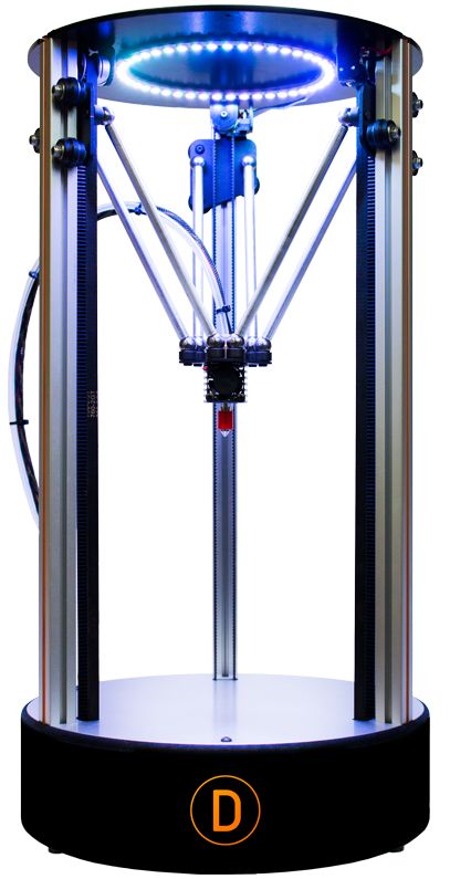
The math is not difficult, but for a printer a lot of square roots must be done. Control boards based on 8 bit processors are struggling doing these calculations so a lot of fine software optimization were done for the delta geometry for these processors. 32 bit controllers are becoming the controller boards of choice more commonly for delta printers as they have much faster processors and do not struggle with the math at all. It shall be noted that the three sliders columns can be on positioned on a non-equilateral triangle and asymmetric dispositions were tested, notably the 'Square' delta with angles of 90°,90° and 180°.
Geometry of a linear delta
Schematics
The arm angle with effector at center is the result of the arms length, minimum angle and angles of the arms while at maximum diameter. For minimum angle of 20°, this angle is around 60° for maximum diameter arm verticals, but if the minimum angle is increased, it may be higher. Minimum angles of 22° will gives an angle of 63° with vertical arms.
Arms may not be able to reach the vertical due to clearance problem, notably with the part cooling fans or effector accessories. In that case, for a given minimum angle, arm length may be reduced and the angle while effector is at center will be lower.
On the other way, some printers have arms capable to go over vertical (e.g. Rostock Max).
The minimum arm angle, while effector is at maximum diameter, is one of the basic design parameters. It is important for effector stability, precision and carriage speed. A low angle induce high carriage speed for a given effector horizontal speed. Low angle also decrease effector stability. Generally, 20° angle is considered as a practical minimum and induce a carriage speed 2.75 times higher than effector horizontal speed. Some printers with theoretical minimum angle of 15° may experience lost steps at their maximum diameter.
Speed up coefficient for given arm angle
| mini angle | speed multiplier |
22. 5° 5° | 2.41 |
| 20° | 2.75 |
| 17.5° | 3.17 |
| 15° | 3.73 |
| 12.5° | 4.51 |
Arm space does not influence movement calculation, but have an importance for the effector stability. Best stability is obtained for the minimum offset, with the maximum possible arm space for this offset (minimising b dimension).
Reachable area
For a given minimum angle, the reachable area is a triangle with bulged sides, with the ends of the triangle oriented toward the columns, which cannot be accessed without impacting the column. Then, for simplicity, the reachable area is generally considered circular. It might be interesting to evaluate the real reachable area when one want to inscribe a rectangle or square in the printing area. The accessories (belts and fans) are critical for the real usable area.
Schematic
- Green : the area which may be reachable without obstacle
- Orange : the practical area taking into account the clearance required between effector and columns.
Delta columns and axis names
View from top
Effector stability
What is effector stability ?
This is the fact that an effector resist to tilting moments. The tilt may displace the hotend nozzle and creates imprecision. It also have an effect on level measurement sensor while the sensors are offset from the hotend. Two things have important effect on an effector stability:
- The geometry, as different geometries may induce higher or lower loads on arms and articulation, so higher or lower deformation. A geometry reducing the load will increase precision.
- The moment resistance induced by arm articulation, say a cardan will resist to torsion induced by the effector, while ball articulation will not.
The moment which will induce tilt will be created by :
- Inertia
- Load on the nozzle
- Friction in articulation, which may be significant for some types of articulations.
How to improve geometry
- A small offset will reduce the load on arms/articulation for a moment and shall be researched.
- For a given offset, the distance between the centers of articulation (noted 'b' on drawing) will modify the moment created by side loads. The lower this space, the better the stability. When these articulation are merged, the geometric stability is very important, as there is no possible level difference in the merged articulations, hence, no possibility to have an 'articulated' tilt. This solution is used by example on the Spiderbot delta.
Position of the hotend
What is also very important is the position of the hotend to minimize the effect of effector tilt. Experience show that a nozzle near the effector plane seems the best solution. However, care shall be taken to limit the raise of the center of gravity, to avoid creating dynamic moments.
Quantifying the effects of the geometrical stability: TES coefficient
Understanding that there are other causes that the effector stability to nozzle movement imprecision, it is however interesting to quantify the displacement due to geometrical instability.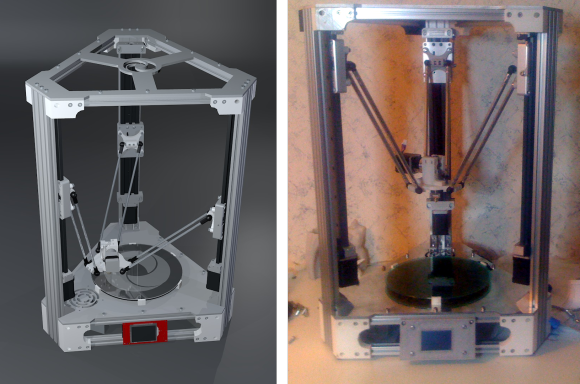
A coefficient could be defined, that we may called TES, for tilt effector stability, which will not quantify the effector instability, but its effect on the hotend, by combining the moment effect and the displacement related to the distance between the virtual articulation and the nozzle location.
a being the lever due to arm space (see drawing) b being the space between balls (articulations)
- Tilt geometric load moment is related to a/b, a being proportional to arm space
- Tilt stiffness is proportional to arm space
TES = (Arm space)²/b, Dimension units shall be mm.
It is important to note that the TES does not depend from arm length, only effector geometry. Indeed, the arm stiffness in their axis is huge compared to other elements, notably articulation stiffness, so the arm length have nearly no effect on tilting stability. This is why you could install the small Kossel mini effectors on large printers without problems. It shall be noted that for merged articulations, this coefficient will be infinite.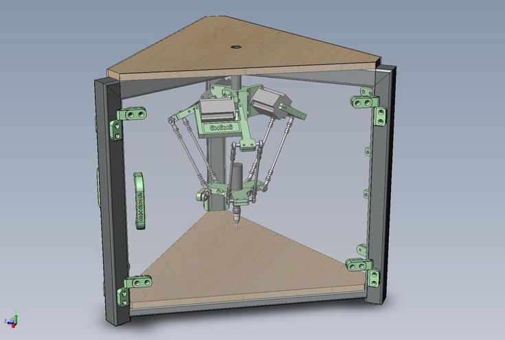
This coefficient is calculated in the OpenScad delta simulator.
Implementation
The practical improvements added by a good geometry is closely related to the quality of the mechanical implementation. By example, if you widen the arm space to improve stability, but the side extensions on the carriage to reach the new width add excessive flexibility, you may have at the end reduced the real stability. It shall be noted that wider arm space does not raise or decrease the moment and only help to fight play in articulation. If your problem is the rotation of the carriage, that is the carriage which shall be reinforced, no geometry can help.
Interactive web simulation
Linear deltas
- GeoGebra dSim graphic simulator for linear delta, use sliders to adjust parameters. Can be viewed in 3D with red/blue glasses.
- Thinkyhead Deltabot calculator for linear delta, enter numbers for simulation.
Rotational deltas
- Parola Java based simulator, rotational delta with many options
- http://arvc.
 umh.es/label/delta.html
Simulation on software
- OpenScad delta simulator for linear delta with active simulation, with common printers datasets predefined. Change variables values for simulation. You can see a film here or here (Fisher Delta)
Delta calculators
Linear deltas
- http://www.heliumfrog.com/deltarobot/details/details.html Excel sheet calculator for linear delta
- https://github.com/Jaydmdigital/mk_visual_calc OpenScad calculator with visualization dedicated to Kossel
Rotational deltas
- marginally clever Online calculator
- Trossen robotics forum
Math and research papers
- File:Rostock Delta Kinematics 3.pdf Comprehensive paper of Steve Graves about linear delta kinematics
- https://groups.google.com/forum/#!topic/deltabot/V6ATBdT43eU Deltabot forum thread on Steve Graves paper with other useful resources
- http://robinsonia.com/wp/?p=161 math explanations for linear delta
- http://scholar.
 rose-hulman.edu/cgi/viewcontent.cgi?article=1000&context=mechanical_engineering_grad_theses Linear delta research paper, but with the sliders parallel to the effector plan.
Rotational delta are a quite common research topic, notably for university students.
- http://www.ohio.edu/people/williar4/html/pdf/DeltaKin.pdf Rotational delta kinematics.
Calculation links
- https://hackaday.io/project/963-firepick-delta-the-open-source-microfactory/log/3588-6152014-delta-mechanism-simulation-and-accuracy-determination (Rotational delta)
Simulation without source/access
Some people have done Delta simulation on CAD/Math software, but not publicly release them.
- https://www.youtube.com/watch?v=8_6QfZ6DJfU film of a Simulation with Matlab
- https://www.youtube.com/watch?v=K2zxvHq3iC8 film
- https://www.youtube.com/watch?v=OwI6hYHWbjw A python simulator, undisclosed program.
Calibration
- http://forums.
 reprap.org/read.php?178,639039 Arm length calculation from printing part
 - http://escher3d.com/pages/wizards/wizarddelta.php web calculator for calibration parameters
- http://forum.seemecnc.com/viewtopic.php?f=36&t=8698 calculator for calibration parameters
- https://github.com/hercek/Marlin/blob/Marlin_v1/calibration.wxm Calibration calculator running with WxMaxima
- http://forum.seemecnc.com/viewtopic.php?f=82&t=7640 forum thread about Heuristic calibration algorithm
In addition to site licence GFDL1.2, this page is also released under license CC BY-SA 4.0
delta printer
Reviews
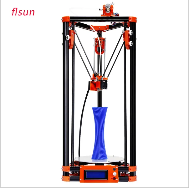
FLSUN 3D Metal Frame Kossel Delta Kit Anycubic Kossel linear plus FLSUN 3D Metal Frame Large Print Area 3D Printer
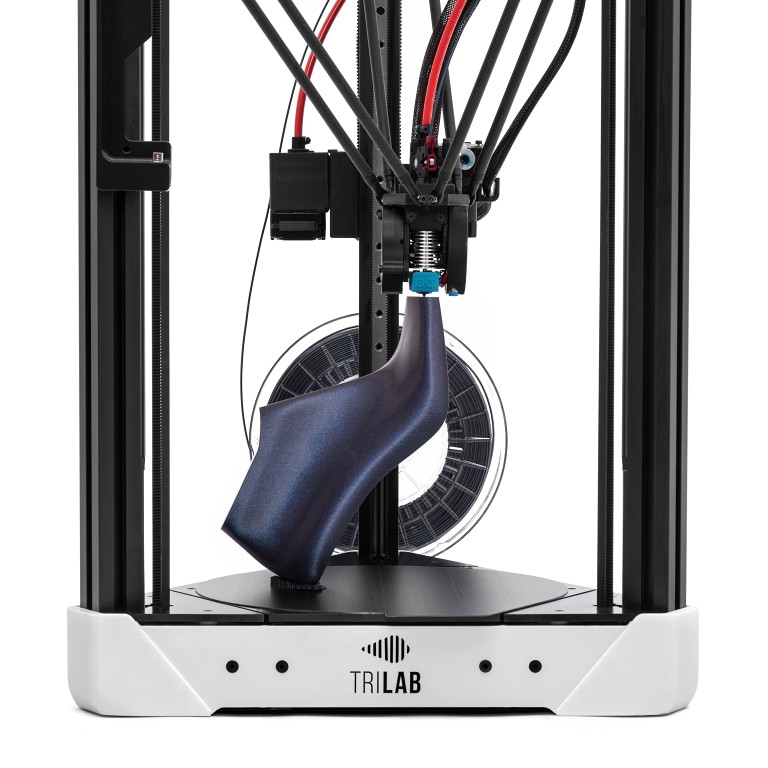
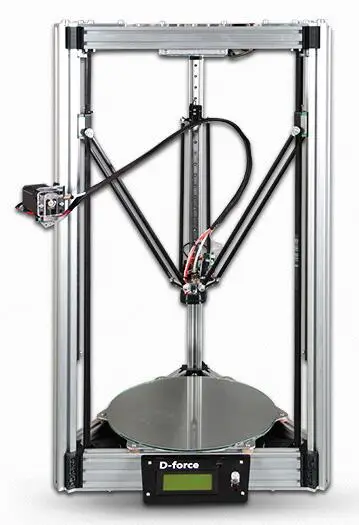
The Delta Printer is a 3D printer with Cartesian kinematics (Delta - kinematics) operating in the XYZ coordinate system. They differ from counterparts with other types of kinematics, higher printing speed, a fixed platform, which avoids “wobble” and the likelihood of distortion, and a large print height along the Z axis due to the vertical arrangement of the rails.
Anycubic Kossel and Anycubic Prediator, very popular in the Russian market, were discontinued and Anikubik did not offer any alternative. But to the delight of fans of fast and beautiful 3D printing, a young and successfully developing Chinese company FLSUN from Shenzhen took advantage of this and offered the market a line of 3D printers Delta . In the sale of the 3DSN store there are models from a warehouse in Russia and on order, wholesale lots.
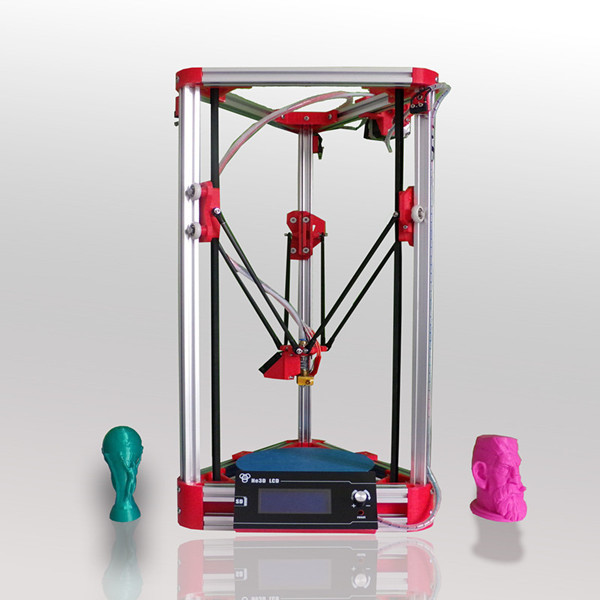
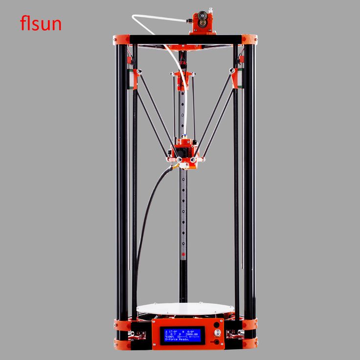
- Budget Delta Printer - 3D printer Flsun Q5 Delta (Kossel)
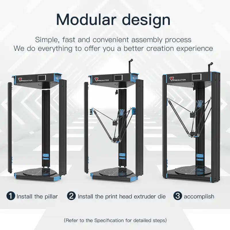
Compact budget Delta 3D printer with a modular structure. It has simple assembly, maintenance and convenient operation.
Ø 200 x 200 mm build area
Auto leveling
32 bit motherboard with TMC2208 drivers
High speed 3D printing up to 120mm/s.
- 3D printer Flsun QQ S PRO Delta Kossel
The FLSUN QQ S PRO 3D Printer (Delta Kossel) is an affordable delta 3D printer offering a fairly large build volume of 255 x 365mm diameter and easy to use features such as automatic bed leveling and the ability to remotely control the printer via Wi-Fi connection -Fi.
Working chamber Ø 255x365 mm
Nozzle working temperature - up to 270 ℃
Heating table temperature - up to 110 ℃
Automatic leveling
Noise level 50 dB
Feeding system: Bowden drive
Filament diameter: 1.75 mm
Nozzle diameter: 0.4 mm
Interface: SD card, Wi-Fi, USB
Size: 286x348x0703 mm
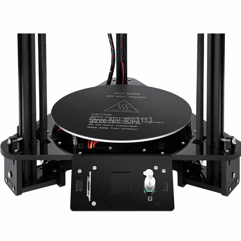
Weight: 13 kg. Equipped with linear rail guides. Glass coated with a special layer for better adhesion.
Construction material: aluminum alloy 6063
Nozzle temperature: ≤ 240 ℃
Table temperature: ≤ 100 ℃
Leveling type: automatic
Motherboard: 32bit
mm/s - 5020mm with
Maximum idle speed: 300 mm/s
Extruder cooling: double fan
Print size: 260x330 mm
Printer size: 440x390x960 mm
Package size: 88x42x20.5 cm0003
Weight: 16.5 kg
More interesting articles
brtv
Loading
11. 09.2022
1486
fourteen
Subscribe to the author
Subscribe
Don't want
Hello my friend! It will be about the repair and review of the Chinese extruder "wellzoom" You have long...
Read more
four
Follow author
Subscribe
Don't want
This year, Raise3D released the MetalFuse metal 3D printing system, consisting of a 3D printer...
Read more
nk.xcfg
Loading
05/10/2016
38154
117
Follow author
Follow
Don't want
“A good tester won't even launch the app.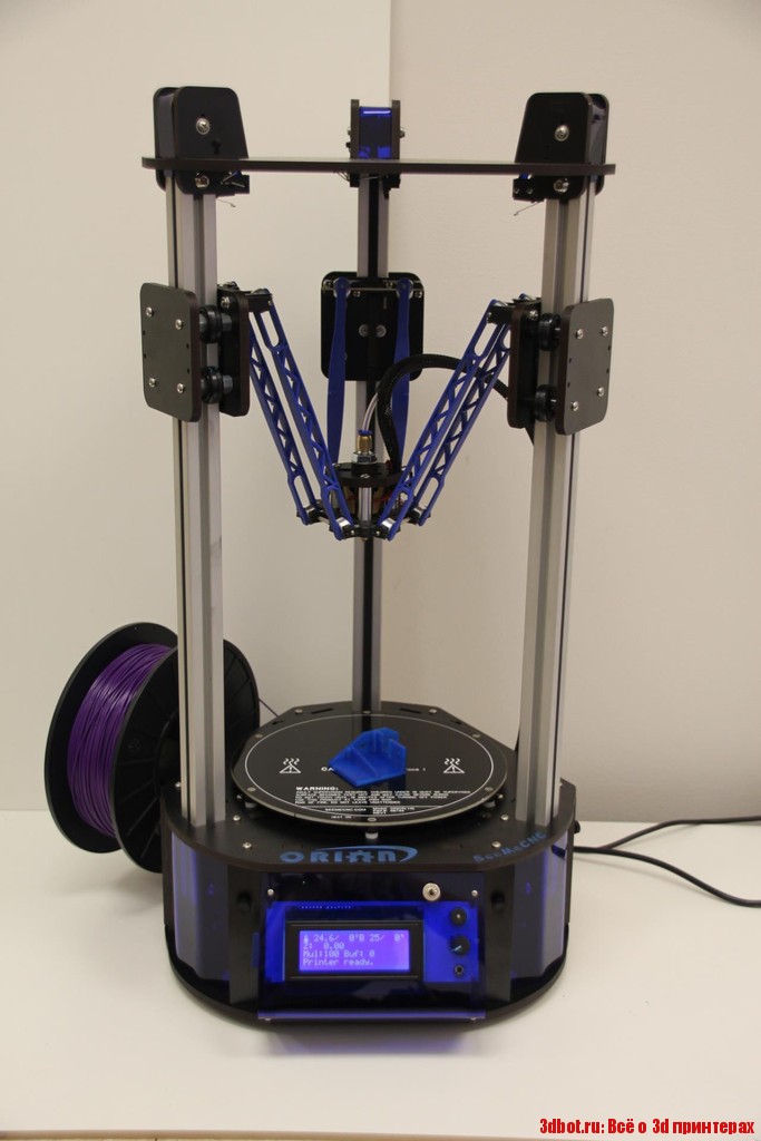 ” (heard at work) Based on real...
Read more
Delta Tower XL Dual 3D Printer
Delta Tower is a renowned manufacturer of large size FDM 3D printers. This company is based in Switzerland. It manufactures high-quality 3D printers for printing large-scale products and printing on an industrial scale. Each product printed on the Delta Tower printer has the traditionally high quality of "Made in Switzerland" goods. From the outside, Delta Tower 3D printers have a sleek, simple design that, combined with high-quality construction components, makes Delta Tower printers a serious platform for industrial and mass production for a long time to come.
Delta Tower 3D printers are able to print products of almost any size thanks to the introduction of innovative technologies and deep scientific research to which scientists, architects and designers have devoted themselves. These printers can be found in education, design, medicine and architecture.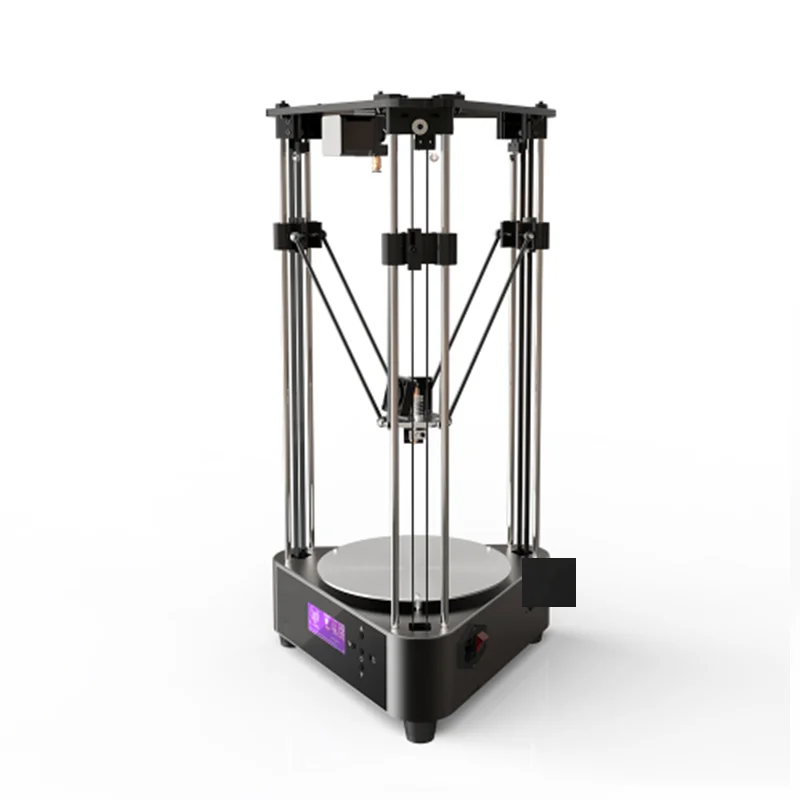 The Delta Tower 3D Printer is able to print at high performance and is virtually silent.
Delta Tower printers are designed with special high pressure nozzles that are required for printing large items. These are special Matrix nozzles developed by the company's engineers. They have seven holes and an optimized internal geometry, resulting in a higher flow rate.
Delta Tower 3D printers can be customized for special requirements and special sizes of printed projects. Implemented the ability to upgrade and expand both hardware and software. All design and software components can be easily changed and modified for any type of printing.
The company produces a wide range of 3D printers, including models with a large, cylindrical printable area, with a diameter of 40 to 200 cm, a height of 70 to 400 cm. Delta Tower printers can print two or three products at the same time. This greatly improves productivity and production capability.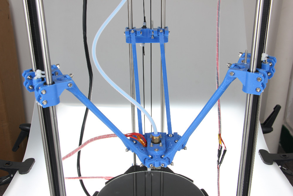 In addition to large, industrial models, you can buy 3 D printer Delta Tower and for small, small-scale production. The company constantly continues to develop new models of 3D printers for a variety of fields.
The DeltaTowerXLDual 3D Printer is a printer with a unique delta design. The print head is located between three vertical guides arranged in a triangle. But, perhaps, the most important characteristic is the dimensions of the device, now the print area has just a huge diameter - 600 mm and a height of 850 mm. This, for comparison, is almost 2 times higher than any standard 3D printer. This design and dimensions allow you to print products of the maximum size. The unique design adds aesthetic appeal and versatility.
The work platform is automatically calibrated to get you started faster. The platform also has an auto-heating system. This property makes it possible to print products from ABS plastic. It should be noted that the structure of the device is very strong, made of aluminum.