Rhino 3d printing tutorial
Rhinoceros 3D tutorial
3D Printing Tutorials
Contents:
- Introduction
- Create your own 3D object
- Convert a 2D image into a 3D object
- Prepare your 3D object for 3D printing
Introduction
This 3D modeling software tutorial is written and designed to provide 3D printing enthusiasts with accurate instructions for designing 3D files that are 3D Printable thanks to Rhino 3D CAD software.
In this 3D CAD tutorial, you will learn the best practices for modeling, correcting and exporting an object for 3D printing using Rhino software. At the end of this Rhino 3D tutorial, you will learn how to:
- Design a printable 3D file
- Manage and export valid 3D files for 3D printing from Rhinoceros
- Avoid mistakes that occur when designing 3D files for 3D printing on Rhinoceros
Then, you will be able to upload your 3D file on our website and 3D print it!
Rhinoceros (Rhino) is a 3D modelling software specialized for free-form NURBS (non uniform rational B-spline), created by Robert McNeel & Associates. NURBS is a mathematical model that renders curves and surfaces in computers graphics. This mathematical model offers great flexibility and precision in 3D modelling.
Rhinoceros is a CAD software commonly used for industrial design, architecture, marine design, jewelry design, automotive design, CAD / CAM, rapid prototyping, reverse engineering, product design, furniture design, as well as the multimedia and graphic design industries. Product design’s easy thanks to this 3D modeling tool. Rhino software is also great to create CAD models for rapid prototyping with 3D printers. Indeed, Rhino models can be saved in a file format compatible with 3D printing.
A basic understanding of Rhinoceros is required in order to get the most out of this CAD software tutorial. Rhinoceros provides lots of great videos and tutorials on its website for getting started with Rhino.
You can buy Rhino 3D or download a 90 days trial version of Rhinoceros V5 for free. You will also find some plugins for Rhino 3D that will help you get a great Computer-Aided design experience and create the best CAD models.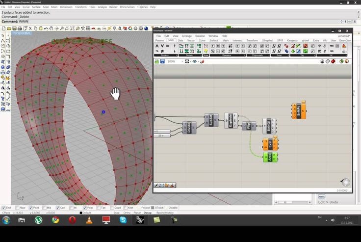
Rhino Models: Design a printable 3D file
1.1. Before starting to model
Before you start 3D modelling anything using Rhino there are some factors that should be considered.
Key concepts for 3D modelling with Rhino
Rhinoceros works with a 3D modelling category called NURBS which is different than regular mesh 3D modelling. However for 3D printing in Rhino it is still necessary to create a mesh after the 3D modelling process. For this reason it is important to keep in mind and clarify some basic 3D modelling concepts.
NURBS 3D modelling concepts
- Curve: are basically the points, lines and segments that make up the sketch model.
- Surface: is a plane without thickness created between a group of closed curves.
- Polysurface: is a set of multiple contiguous surfaces that build a volume.
- Solid: is a completely closed and joined polysurface that create the 3D model. It is different from a mesh.
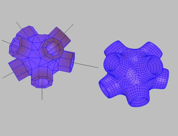
Mesh 3D modelling concepts
- Vertices: is a position along with other information such as color, normal vector and texture coordinates.
- Edges: is a connection between two vertices.
- Faces: is a closed set of edges that form a plane without thickness.
- Polygon: is a coplanar set of faces that build an open or a close volume.
- Mesh: is a collection of vertices, edges and faces that define the shape of the 3D model. It is different from a solid.
A solid in Rhino is built with NURBS, which is different from a solid built through mesh 3D modelling. Knowing the difference between these two 3D modelling approaches is important for a successful 3D printable model.
Global 3D printing 3D modelling process with Rhino
Objet dimensions and measures compatibility
An important factor to consider before starting your 3D model is the size of the object relative to the professional 3D printer that will be used to produce the piece.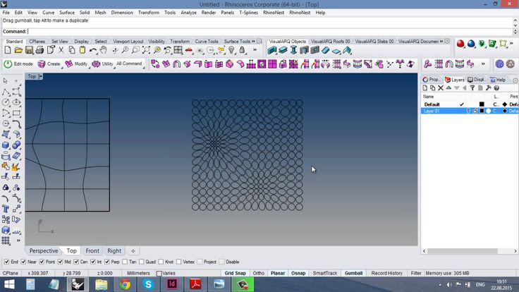 For example, if the model is bigger than the 3D printing area, the model must be adjusted.
Also the desired dimensions of the piece should be coherent with the dimensions used while 3D modelling, as well as the units settings of the file that suits better to the project (inches, centimetres, millimetres). This can be found at ‘File/ Properties/ Document Properties/ Units’.
You can work with the most suitable units for you or for the project while 3D modelling. However before exporting you must always switch the units to millimeters and allow Rhino to scale the model.
Rhino unit settings are always interpreted as millimeters when imported into other programs. So, for example, if you modeled a part of 5 cm × 5 cm × 5 cm using centimeters as a unit, you will obtain measurements of 5 mm × 5 mm × 5 mm when exporting your model in STL. This is why you must change the units to millimeters no matter what unit of measurement you used to begin your model.
Grid adjustment and measurement
It is important to be aware of the measures at all times while 3D modelling as this will allow you to have absolute control over the size of your model.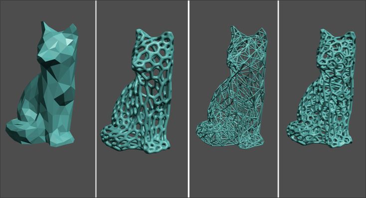 The main tool in Rhino used to visualize the size of your objects is the display grid in the background of the viewports. The grid allows you to work precisely using the “Grid Snap” and the “Linear Dimension” tool.
You can set up and personalize your grid at ‘File/ Properties/ Document Properties/ Grid’.
The “Linear Dimension” tool is Rhino’s technical drawing tool and can be used to find a precise measurement of the model. You can find it at Dimension/ Linear Dimension.
The dimension will appear on the arrows bar that was used to set up the file units, after selecting a starting and ending point for the line.
Tolerance settings
It is recommended to take a look at the tolerance settings file. This can be found at ‘File/ Properties/ Document Properties/ Units/ Absolute Tolerance’.
The 3D file tolerance should be set up depending on the model size and 3D modelling units. For example a 0.001 mm tolerance for a model with a size of 500 mm × 500 mm × 300mm will be an exaggerated tolerance.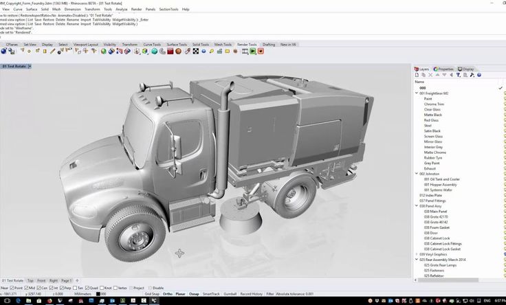 Instead a 0.001 mm tolerance for a model with a size of 70 mm × 70 mm × 70mm will be reasonable.
This aspect is also relevant for the mesh creation that will be explained later in this tutorial.
Real time tool verification
It could be also useful to turn on the Check New Objects tool by typing it in the command line “CheckNewObjects”. This command will constantly check every geometric figure created to verify if it is valid (not bad) and pops up a message when the figure created is corrupted.
1.2. Proper 3D modelling for 3D print
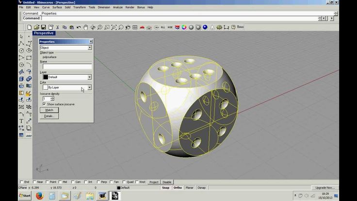
When starting out with Rhino, as in any other 3D modelling software, it’s essential to keep in mind that the 3D modelling characteristics for 3D printing are different than your average rendering or animation model. Therefore separate guidelines need to be respected throughout the 3D modelling process in order to obtain a printable model. In this tutorial, various images are used to display the process – these images correspond with models that are most suitable with Sculpteo’s plastic material.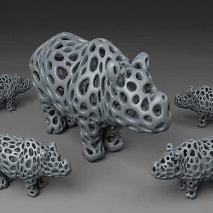 It is also important to note that Sculpteo uses Selective Laser Sintering (SLS) to 3D print plastic models. This tutorial takes both of those factors into consideration, however it is important to consider the specific material and manufacturing process that will be used for your project while creating your model. For more information, you can refer to our materials page. Next, you will see the precautions that must be taken into account to create correct solids during the 3D modelling phase. Watertight model While creating a 3D model it is important to understand that a 3D printable model must be “watertight” this means it should be designed to prohibit the entry of water. Most common mistakes using Rhino for 3D modelling that occur with non-printable models are the open polysurfaces, bad geometry and naked edges result in a non watertight model. Closed polysurfaces and non naked edges A closed polysurface is a set of multiple contiguous surfaces that build a closed volume called also solids.
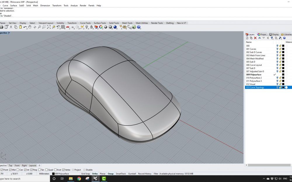 Namely the volume walls have no holes and they are all attached. A model made of a closed polysurface will normally look like in the picture below. They are usually built with Rhino’s surface and solid menu operations . However you can also (voluntarily or involuntarily) create models with an open polysurface which are different than a models made with a closed polysurface. Most of the times, in this kind of model, you can appreciate the interior structure as shown in the picture below (red oval) but models like this are not 3D printable because, even if they exists, the surfaces have no thickness. On the other hand, sometimes 3D models looks like they are made with a closed polysurface but they are not, this is what is called naked edges. A naked edge is basically a surface edge that is not attached to another surface edge even if both surfaces are contiguous, consequently creating an open object. In the picture below you can see a detached surface selected that, when not selected, may look as a regular closed object.
 This could happen involuntary for many reasons, most of the times it’s because of an unsuccessful 3D modelling operation like split, trim, rebuilding surfaces or the act of exploding and joining surfaces . This last one is paradoxical but true and it happens when multiple surfaces are joined at the same time. After using these operation it is always recommended to verify the object (as you will see further in this tutorial) because some surfaces may need to be joined separately to avoid creating naked edges which will certainly be a problem during a 3D print. Valid object Valid objects are objects built without bad geometry errors. Bad geometry models or bad objects in Rhino are those who violate certain NURBS rules or have a structural problem. Most often, the bad objects are surfaces in a solid, but bad curves also happen occasionally as well. This happens for many technical reasons, in a surface is usually because the trim curve is bad. This is not something you can make intentionally but it often happens after join operations or other commands that also join objects like booleans operations .
 These operations split edges and adjust trim curves that in some cases are smaller than the absolute tolerance of the file producing bad geometry. Material reduce There are several reasons why digital models for 3d printing are hollow but the main reason is the amount of material that will be used to produce the model. In 3d printing — unlike other production techniques — the cost of fabricating an object is not dictated by the complexity of its shape, but by the amount of material that is required to produce the design. Therefore, making your object hollow will positively affect the manufacturing cost of 3D printing, by decreasing it to less than 60% or 70% of its initial cost. Another important reason to hollow a model, is keeping your product lightweight. For example if you already have a model and you would like to rescale it to produce a different size of it you can hollow your model to make it bigger but keep it light. But simply hollowing your model doesn’t affect your product; the hollow interior must have at least two holes to the drain the excess printing material.
 This is a restriction SLS’ printing process, without the holes to let the material drain it will be trapped within the physical object. The Sculpteo online uploader has recently been enriched with automated hollowing feature that allows you to handle the hollowing process online. This feature automatically generates the inner shell of your model letting you simply choose the required hole positions on your model. To learn more about Sculpteo’s new hollowing feature and try it now, you can upload your 3D file and click on “Optimize” tab after choosing your material. Next, you will see how to hollow your model in order to reduce the material used during a 3D print. This will allow for a bigger, lighter, and more economical version of the object using Rhino. You have to first scale the model to the desire size. Illustrated in this example the model is doubled in the size from 6 cm to 12 cm. You should keep in mind that the minimum wall thickness for the Plastic material is 0.8 mm and the maximum wall thickness must be coherent with the model size.
 An overly thick wall in a small object will produce geometry errors depending on the curvature of the interior of the model. It is recommended to try different wall thicknesses to find the best for your object. A rod made with Sculpteo’s polyamide plastic, for example, is rigid at 2 mm thick (check the material guide for more information about polyamide design guidelines). Once you have determined the right size you should extract a surface to make it an open polysurface. For this you can use the “Extract Surfaces” tool by typing “ExtractSrf” in the command line and selecting the chosen face. Then you can eliminate the face. After that you can use the “Offset Surface” tool by clicking on it in the left bar menu under Filet Surface/ Offset Surface or typing in the command bar “offset srf”. With the object selected, you turn on the option “Solid=yes”, and set the “Distance” to your desired length (2 mm in this example). If you do not want the external form of the object to change you flip the offset direction to the interior of the model with “FlipAll”.
 All this can be done using the command bar. You will result in a solid (or closed polysurface model) with a uniform 2 mm wall thickness. One single solid part Sometimes, the 3D modelling parts are made using many different solids that intersect each other which finally compose one single part. Even if the model is constructed with many different cubes or cylinders, the final piece should be a singular and compact solid in order for a successful 3D print. When you select a single part of your model, you usually should see in the command line “1 polysurface added to selection” this means your part has been added to the entire object. Also your model can be composed of different parts that do not intersect but are instead extremely, or even entrapped within another object. This manner of 3D modelling is particularly helpful when creating moving parts or other types of inserts, sockets, articulations, etc. In this case you have to keep in mind the 3D modelling tips for this kind of parts and understand that an articulation is made from two single solids and not form an intersected solids.
 This is very important when producing a 3D printable file without errors. You can find more information about articulations and design guidelines depending on the material on our materials page.
1.3. Color and textures for full color printing
Rhinoceros includes some great tools for color and texture mapping, but it is not the most suitable software to add colors and textures for 3D printing purposes. It mostly depends on the projects needs and requirements. You can also use color and texture mapping after 3D modelling in Rhinoceros with other powerful CAD software applications such as 3D Studio Max, and the free software. Its features will be described in other tutorials dedicated to it. Color 3D printing adds color and texture to the final mesh model using color and texture mapping tools. The difference between a regular 3D printing model and a color 3D printing model is that the second one should be exported as a .obj format after the mesh creation instead of an . stl file. A color 3D printing file is made of several files with the color and texture information. When exporting an .obj file, an .mtl file containing the texture mapping informations is automatically created by the software: these two files, and all the textures image files used in the model, should always be kept together in the same folder. Colors and textures could be added before or after mesh creation. The first thing to do before starting to add color and textures is to go to the right side column at the “Display” tab and switch the “Display mode” to “Rendered” having selected the perspective viewport. This will allow you to see the modifications related to color and textures while applying it. In order to add colors to the object you have to select the object and go to the right side column at the “Properties” tab select the “Paint tube” button , select the option “Assign material by : Object” and change the color in the “Basic Settings” blank space. Rhinoceros comes with some default materials for rendering purposes.
 This materials can also be use for color 3D printing purposes. Before starting you must activate the “Rendered Display Mode” as explaned with the color. You can access the default textures and materials going to the menu “Panels” and select “Libraries”. A new window containing the textures and materials will appear, you will be able to click and drag them from the library to the object in order to add them. For more precise purposes you can use the textures mapping options in the right side column next to the “paint tube”. This options will allow you to place the textures as you desire on the surface object. Once you finish, you select the object and you exported as .obj file format. The software will produce the files needed to color 3D printing. You should upload all the files together in a zipped folder to Sculpteo’s website for a successful color 3D printing.
Manage and export valid 3D files for 3D printing from Rhinoceros
2.1. 3D model analysis
When 3D modelling for 3D printing, it is essential to constantly verify the cohesion between your model and the tools in order to build a polysurface objects. Below, you will see the verification tools that will help to identify the model errors during the 3D modelling NURBs phase.
Open polysurfaces detection
The simplest way to identify an open polysurface is with the “Select Open Polysurfaces” tool
.You can find it in the toolbar under the
drop downmenu ‘Analyse Direction/ Show edges/ Select Open Polysurfaces’ or you can just type “SelOpenPolysrf” in the command line.
When an object is made of an open polysurface, it will light up as a selection the while the other part will stay intact because it is a regular surface.
If the model stays closed, you will see “No objects added to selection” in the command line.
By doing this, you can find out which object is made of an open polysurface. If you have a file with many different models you will be able to isolate it more easily with the “invert selection and hide objects” tool in the ‘Standard menu tab/ Hide objects/ Invert selection and hide objects’ section.
Once you have the isolated object you can proceed to do the naked edges detection.
Edge analysis for naked edges
The edge analysis tool will help you detect where and if a polysurface is open. You can find this tool in the main menu bar at ‘Analyse Direction/ Show Edges’ which will open up a new smaller box where you need to choose the object to be analysed. You can also open this tool by typing ”ShowEdges in the command line.
This command will light up the open contour according to the selection color in the edge analysis box.
Bad geometry
The “select bad objects” tool
allowsyou to find where the bad objects are. You can access it in the main bar ‘Analyze direction/ Select Bad Objects’ or by typing in the command line: “SelBadObjects”.
To have more detailed information about a bad object, you can run a diagnostic using “Check objects”
available in the main menu under ‘Check objects’. A popup window will give you more information about the model e.g. if there is any bad geometry or “Rhino
object is valid” meaning there is no bad geometry.
You can select the model and go to properties in the right column to select details
atthe end of the
colum. It will give you of general information about the model along
whiththe geometry information.
2.2. Fix NURBS 3D model
Repair naked edges After finding the naked edges, you can fix them with a join
operation .You can then join the detached surface to the main body of the model and close the object. However, sometimes there are missing surfaces. In this case, the best method to solve the problem is to create a new surface that will be in perfect contact with the surrounding surfaces edges; use join to create a closed
polysurface. When the surface edges are more distant to each other than what your Rhino file tolerance allows -for example when 2 surface edges are 0.1 mm apart and Rhino tolerance is 0.001- the join command won’t work. This type of naked edge can be fixed by using a forced union. If precision 3D modeling is not important for the 3D modeling work, this could be a quick fix operation. It allows Rhino to join the edges without taking the minimal tolerance into account. You can find the forced union tool under ‘Surface menu/ Edge Tools/ Join 2 naked edges’ or by typing “JoingEdge” into the command line. This is a quick solution, not the best one, but it is better to have a clean closed
model. Do note, the Join Edges operation may not work if you are exporting the solid as an IGES or STEP file (to then be used for purposes other than 3D printing). Fixing bad geometry As was mentioned in the valid objects section, bad geometry is mostly generated from bad surfaces due to an error that occurs during the adjusting of the trim curve. Usually, bad surfaces are fixed by making the model explode and then rejoining it. If this does not fix the model, it is because there are complicated NURBs problems in the structure. You can try to fix them with the following tool operations:
- First of all, identify the bad surfaces and hide everything else temporarily. You can separate the bad surfaces from the polysurface using “Bad Surfaces Extract” by typing “ExtractBadSrf” in the command line .
- Once you have the bad surfaces isolated, proceed to restore the edges of the surfaces to their original state before they were joined – with the command “Rebuild Edges”. You can find this in the main menu ‘Fillet Surface/ Rebuild Edges’ or typing in the command bar “RebuildEdges”. This operation will detach the surfaces so you can rejoin them again. In some cases, this might work. After this operation, you should check if the surfaces are repaired or if there are at least some of them fixed.
- If the surfaces were not completely fixed, you can select a bad surface and remove the trimming boundary from a surface using the command “Untrim” followed by “keep trim objects”.
 This is available in the main menu ‘Fillet surface/ Untrim’ or typing in the command bar “Untrim”. Select the trim curve and trim it again. Then check if the surface is no longer a bad surface. You should apply the same operation to the other bad surfaces.
 - For the last part, try to unhide everything and make them all join up again. Check for bad geometry with “Check objects” . If this does not work, it is usually because the join operation is trying to force things together that do not fit correctly. If so, it is recommended to find the bad surfaces and analyse the union with the contiguous surfaces.
Multiple solids model As explained before, in the “proper 3D
modellingfor 3D printing” section, your model or part should be made out of one single solid or closed
polysurface. If this is not the case, you can select both solids and make one single solid using the tool “boolean union” . This will fuse the two solids into a single one. You can find this tool in the left bar or under ‘Solid/ Union’.
2.3. Create and export a mesh
As Rhino use a
NURBsapproach for 3D
modelling, you must produce a mesh in order to create a 3D print file. You can export the Rhino model
as .STL (stéréolithographie) from ‘File/ Export Selected’ and save it to create a 3D print file. For obtaining optimal results, it is recommended to have a better understanding and control of the mesh creation settings before you start exporting. You can create a mesh without exporting the solid by using the command “Mesh” – located in the main left command bar – or by typing in the command line “Mesh”. Right away a popup window will show with the “Polygon Mesh Options” along with some simple controls. In order to have more control over the
mesh, you will have to switch and set “Detailed Controls”. These controls will allow you to set up the density and quantity of the mesh. Next, you will see some tips to create the mesh that best suits your needs. Tolerance for mesh creation A mesh is composed of many faces that actually make up your model. The quantity of the faces depends on the mesh density. A model with few faces will look faceted or it will have a low polygon appearance. A model with many faces will look smooth and have a high polygon appearance. The more faces, the smoother your model will look but be careful because an exaggerated number of polygons could turn your 3D model in an oversized file, making it more difficult to handle. A good 3D print mesh looks nearly black. The polygons distribution is organized and balanced within the model. A good example is the high polygon picture displayed above.
the polygons quantity must be conforming to the model size. For
example: an object of 30 mm × 30mm × 70 mm will be printed with an optimal surface if you use between 500. 000 and 600.000 polygons and smaller objects like jewelry (rings, earrings or pendants) use something close to 150.000 polygons for an optimal surface. The recommended values in a general way to set up the tolerance for small objects for 3D printing are the following.
- Density: 0.0
- Maximum angle: 0.0
- Maximum aspect ratio: 0.0
- Minimum edge length: 0.0
- Maximum edge length: 0.0
- Maximum distance edge to surface: “The same as the tolerance file” (tolerance settings)
- Maximum edge length: 0.0
- Minimum initial grid quads: “Variable depending on how the mesh looks”
The minimum initial grid is a variable value depending on your model. This number will help us to define the number of quadrangles per surface in the initial mesh grid. Namely, the polygons quantity on each surface. Bigger values result in slower meshing, more accurate meshes and a higher polygon count with more evenly distributed polygons. For example a minimum initial
of 100 produces a mesh almost black and with a certain uniformity in the sides of the model,
howeverthe “S” interior is not really uniform and it
havemany peaks and triangles creating a messy mesh. Instead, if you use a 7000 value the mesh will be more homogeneous and organized. That is why the minimum initial grids
isvariable depending on your model. After the mesh
creation,you can separate the solid from the mesh and you will be able to check the number of polygons in the object. In order to this, select the mesh and use the right column properties tab by clicking in the
bottom “Details”. You will the following within the mesh’s general information: “closed polygons mesh and the number of polygons that compose the mesh”. For example, in the model displayed below there is mesh with
minimum initial grids that have 151667 polygons. This is a reasonable mesh for a model with this small size like jewelry objects (rings, earrings or pendants).
Finally,the model is ready to be exported. Under ‘File/ Export selected’, choose the file emplacement and after
thatthere will be an ending window. Make sure you uncheck the option “export open objects” and leave Binary selected then click ok.
2.4. Correct mesh for 3D printing
Similarly to NURBs 3D modeling software, a 3D printing mesh model is different from a mesh model that is not intended for 3D priting such as for rendering or animation. In the previous sections, you have seen how to create a proper 3D NURBs model in order to avoid issues during a 3D print but sometimes your mesh could still have some errors. That is why it is important to know what kind of errors can arise in a mesh. In the following section a low polygon model will be used as the example to illustrate the problems.
Closed and compact mesh
Like polysurfaces, meshes must not be open to be 3D printable. The mesh must be composed for multiple faces that build a closed volume and it must not have holes. This means that the mesh must also be “watertight”.
The mesh object must be compact meaning no vertices, edges or faces around the main model. All the pieces that make up the model should have a volume, there can’t be faces without any mass.
Manifold mesh
A 3D printable mesh is a correctly manifolded mesh. The term manifold defines a mesh in which all its triangular edges are directly and individually connected to one another creating a closed volume.
Non-manifold errors are generally produced by the following reasons:
- Several faces share one edge
- Several faces share the same point or vertex
- There are some unnecessary faces intersecting the main body of the model or at the interior of the model
Coherent mesh orientation
The faces that compose the mesh may not have the same normal orientation. That means that while one face has a normal direction to the exterior, its neighbouring face can have a normal direction towards the interior.
One single shell
Every part that makes up your digital model needs to be made out of just one shell. When you select a single part of your model, you usually should see in the command line “1 mesh added to selection” this means your part is made of only one shell.
2.5. Mesh analysis
The mesh analysis tools could be really helpful to check – your already exported STL from Rhino – if you want to confirm that everything is right with it or if you have a model that needs to be checked and repaired. Open mesh detection The detection of an open mesh can be done with the command “select open meshes
” .It is located in the top bar in the tab “select” ‘Select Meshes/
Select open meshes’ or by typing in the command line “SelOpenMesh”. The open mesh will light up if it is open. If the model is closed you will see “No objects added to selection” in the command line. This process lets you find out which meshes are open. Once you have the isolated the object, you can proceed to do the naked edges or
detection. Non manifold edges analysis The edges analysis tool will help you to find out if there are
non-manifolderrors. The operating mode is exactly the same as the naked edges for
polysurfaces. The difference is that you will have to switch from the naked edges case to the
non-manifoldedges case. You can fiind the tool that will help you in the main menu bar mentioning ”Analyse Direction/ Show edges”. This will make a new small box pop up where you choose the object to be
analysed. You can also open this tool by typing in the command line “ShowEdges”. It is recommended to use the tool with the volume displayed in
this will make it easier to find manifold errors in the interior of the object. The naked edge or manifold error will light up the problematic face or edge. Mesh orientation analysis It is easier to identify the faces (with a normal direction) that present a problem if after running a naked edges test – you can still see a hole in a shaded display mode when your mesh is completely closed and there are no naked edges. This means that the face that
lookslike a hole may exist, but the normal direction is inverted so the light is not reflected in the render. Another way you can see more on the normals
directions, is by using the “Analyze direction” tool. All directions should be oriented to the exterior of the model. This tool allows you to also flip the normal direction but it won’t unify the object. Mesh verification You can check if your final mesh is a 3D printable mesh by running a diagnostic check using the “Check objects” tool that is available under the main menu. A popup window will give you more information about the model if there is any problem with it – or it will say “This is a good mesh”. You can read the description and see if there are no more errors that were mentioned before.
Avoid mistakes that occur when designing 3D files for 3D printing on Rhino
At Sculpteo we have developed some great automatic mesh repairing algorithms that you can easily access online through the upload environment. We can proudly say that these methods succeed in almost all cases in repairing common mesh problems, but as they are automated repairs, you might want to have better control on how your mesh topology should be modified following any repairs. Therefore when dealing with isolated and detectable errors, it is better to manually repair these errors yourself on your 3D modelling software as in rhino, the necessary tools are provided.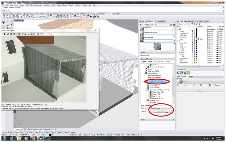
The reason for manually troubleshooting errors is that no automated algorithm knows your mesh as accurately as you do.
Next, the tools Rhino provides to solve the most common problems with invalid meshes will be discussed in the coming paragraphs.
3.1. Mesh reduce
If your mesh’s ‘Number of Polygons’ is more than a 1.000.000, it will be quite difficult for Sculpteo to handle it which also means it contains unnecessary details. Therefore, you need to reduce this number through the “Reduce mesh” command
.
You will have to find a good balance between your model quality detail and the polygons number because the more you reduce the mesh the more it will become faceted.
3.2. Mesh orientation unification
The faces belonging to the same shell of your model might not have a coherent orientation, which means that the normal direction of your faces are not the same as it was explained before in the “Coherent Mesh” section. In order to fix this issue select your model and use “Unify mesh normals” tool
this will put all the normal direction to the same side and will eliminate the problem.
3.3. Mesh hole fill
After running a test with “select open meshes” and “naked edges analysis”, you have find a hole and its location in the mesh. As your mesh should be closed and “watertight” to be 3D printable, the hole needs to be closed. In this case you can use the “Fill hole” tool .
3.4. Non manifold errors
Once you have detected a non manifold edge or faces you can eliminate the excess edge or face. It is recommended to observe the model in the wireframe mode because frequently the non manifold edges are at the interior of the object as in our example. In this case you will have to eliminate the two extra faces that are sharing the edge. It is made evident in the illustration by red colors for the explanation. You can eliminate them using “Delete mesh faces” located in main left bar ‘Mesh Tools/ Delete mesh faces’ or typing “DeleteMeshFaces” in the command line. You select the face and you tap enter to finish the operation.
3.5. Multishell parts
If your model parts meshes are made from multiple shells this may cause a problem when creating a 3D printable file. In this case you should separate the shells to verify if they are expendable. If not you should integrate them to the main shell, for this you can use the command “mesh boolean union” which is available on the main left bar Mesh from surface polysurface/ Mesh boolean union or typing in the command line “MeshBooleanUnion”.
Related Topics
- Return to Top
Get the latest 3D printing news delivered right to your inbox
Subscribe to our weekly newsletter to hear about the latest 3D printing technologies, applications, materials, and software.
How to Prepare Rhino Files for 3D Printing
Time to read: 4 min
We recently wrote an overview on How to Prepare CAD Files for 3D Printing, going over some general considerations and steps to properly export your 3D printing files.
There are some unique considerations to keep in mind when preparing 3D print files specifically in Rhino, so for this post, we’re going to go into more detail on how to export your CAD models here.
Let’s dive in!
Units and Tolerances
Set correct tolerances before you start modelling by finding the tolerance of the program you are exporting your model to and setting Rhino tolerance to be 10 times that (i.e., printer tolerance is 0.1mm, so Rhino tolerance should be set to 0.01mm).
Rhino file tolerance can be set from the document properties window, units tab.
No matter what units you use to create your model, files exported from Rhino are almost always read as mm. Make sure your units are set to mm before exporting your file for printing.
Check Your 3D Models
For successful 3D prints, the 3D model should be watertight, i.e. if you dropped the model in a bath, no water would leak inside.
To achieve a watertight model, you need a closed polysurface. The most common reason models become unprintable is due to bad objects and naked edges.
Bad Object: Objects that violate NURBS rules or have structural problems. They often appear after joining and Boolean operationsNaked Edge: Surface edges not connected to other surface edges, which create open meshes that cannot be 3D printed
Find open polysurfaces by selecting Analyse Direction → Show Edges → Select Open Polysurfaces, and then follow the steps below:
To Prevent Naked Edges
- Select Analysis → Show Edges → Naked Edges to display naked edges in your object.
- Naked edges due to missing surfaces can easily be corrected by filling in the hole with a new surface and joining the new surfaces together.
 Created surfaces and existing surfaces must be within model tolerance to join correctly.
 - If precision is not important, the JoinEdges command can be used to join surfaces forcibly, however it’s better to recreate the bad surface.
- Your NURBS model can be converted to mesh with the Mesh command. SelectShow Edges → Naked Edges as before. In Rhino 3.0 Service, Release 4.0: Under Bonus Tools you will find ‘FillHole’ and ‘FillHoles’ to fix naked edges in the mesh. Make sure to save your NURBS model before this operation as it is difficult or impossible to reverse.
To Prevent Bad Edges
- Use the ‘Checknewobjects’ command to verify objects as they are created. This runs in the background and instantly detects bad objects and corrects objects instantly.
- Many bad surfaces can be fixed by exploding and rejoining the model. If this doesn’t work, that means there are NURBS structural problems in the model.
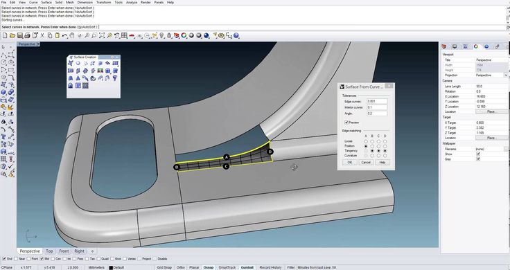
- Explode detected bad objects and use the Selbad or Extract Bad Surfacescommands to delete specific bad surfaces. Use the Rebuildedges command to recreate the deleted surface.
- Using Osnap helps to prevent open curves, a common source of bad objects.
Creating and Exporting a Mesh
Rhino creates a NURBS solid model. However for 3D printing, the model must be exported as a mesh model. To achieve this, follow these steps:
- File → Save As → .STL and select a name for your STL file.
- There are simple controls and detailed controls – always select detailed controls.
- These are the specific settings recommended for 3D printing:
- Density: 0.0
- Maximum Angle: 0.0
- Maximum Aspect Ratio: 0.0
- Minimum Edge Length: 0.0
- Maximum Edge Length: 0.0
- Maximum Edge to Surface: 0.
 0
0 - Minimum Initial Grid Quads: 16
- Refine Mesh: yes
- Jagged Seams: no
- Simple Planes: yes
- Maximum Distance edge to Surface: Less than half of the printer’s resolution. For millimetre unit models try 0.1 to 0.01.
- In the STL Export Options dialog box, set the file type as Binary and click OK.
Check Your Mesh Model
Even with the recommended settings, your STL mesh may have errors that make it unsuitable for 3D printing. Here are the most common problems and solutions:
Too Many Polygons
If your mesh polygon number is higher than 1,000,000, the file will be unwieldy and difficult to print. Small items like jewelry should have around 150,000 polygons, while a 30 x 30 x 70mm object will have more like 600,000. Use the Reduce Mesh command to make your file more manageable.
Incoherent Mesh Normals
The ‘positive’ direction of your mesh faces may not be coherent throughout the model. Use the ‘Unify Mesh Normals’ tool to fix the issue.
Selecting open meshes and performing a naked edge analysis as described above will identify any holes in your mesh. This is easy to fix using the ‘FillHole’ command.
Non-Manifold Errors
Can be caused when multiple mesh surfaces share a vertex or edge. Use the ShowEdgestool as before to find these errors. It’s recommended to view the object in wireframe mode for easier analysis; frequently the excess faces are inside the model. Use the ‘Delete Mesh Faces’ tool to remove the excess faces.
You’re Ready!
Your model is ready to print! If you have any further questions, feel free to contact the Fictiv team here, or check out the Fictiv Capabilities Guide.
Thank you for subscribing!
3D printing from scratch | BHV publishing house
- Description
- Details
- Reviews (0)
Description
The principles of operation of modern 3D printers are considered, advice is given on choosing, self-assembling and setting up such a device, an overview of the most popular models is given. The materials used in 3D printing are described, their comparative characteristics are given. All stages of 3D printing are described in detail: preparing the printer for operation, starting it, eliminating possible printing defects, post-printing processing of products. Attention is paid to working with the free programs Cura, Repetier-Host and the Tinkercad 3D editor, as well as modern 3D scanners that allow obtaining three-dimensional images of real objects….
About the Authors
Dmitry Gorkov is an entrepreneur and 3D printing enthusiast with over 20 years of experience in IT. I decided to create a business in the field of 3D printing in August 2013, having accidentally stumbled upon an article on this topic. After purchasing the first 3D printer, he began to implement his ideas by promoting 3D printing, and after a few months he began to fulfill regular orders. His business began to generate a stable income, which allowed him to develop other projects in parallel. Dmitry teaches master classes, speaks at specialized conferences, and also publishes articles on 3D printing on specialized Internet resources and on his own website http://3d-print-nt.ru.
Valentin Kholmogorov — writer, author of more than 40 books on computer technology, including "Encyclopedia of a personal computer", "Secrets of working in Windows", etc. Valentin's first publication was published in 1993, and since then Since then, in his luggage, there are several hundred articles in online and paper magazines. For many years he has been fond of 3D printing, he independently assembled his first 3D printer in 2014. Valentin's publications can be found in the popular Hacker magazine, as well as on the author's own website: http://holmogorov.ru.
Parts
| Art. No. | 2692 | |
|---|---|---|
| ISBN | 978-5-9775-6599-8 | |
| Number of pages | 256 | |
| Series | From scratch | |
| Binding | Paperback | |
| Printing | Black & White | |
| Year | 2020031 Dimensions, mm | 215 x 165 x 10 |
| Weight, kg | 0. 338 338 |
- ✓ New 2 weeks ahead of stores
- ✓ Prices from the publisher up to 30% lower
- ✓ Promotions and discounts for subscribers only
- ✓ BHV Important News
USEFUL BOOK NEWSLETTER
By subscribing to the newsletter, you agree to the privacy policy and the processing of your personal data.
We also recommend
- Gorelik Alexander Girshevich
Tutorial 3ds Max 2020
1169 ₽
994 ₽ -
AutoCAD Tutorial - Paper Book
1250₽1062₽
Basics of 3D printing - amateur translation. "Fundamentals of 3D printing"
Roketa
Loading
11/19/2022
2656
Miscellaneous
Follow author
Follow
Don't want
47
Hello!
I registered on this site in order to share a book that I read and translated for myself (and with the hope of getting at least some goodies for it, but alas).
This book is freely distributed on the web. It was written by Josef Prusa, a Czech 3D printing expert, creator of the Prusa 3D company and the Prusa series printers. The book describes the basics of 3D printing, basic mechanics, types of printers, filament, the application of the resulting products and some tricks. Contents:
- What is 3D printing?
- Technology 3D Press
- Choosing 3D printer
- Fundamentals 3d press
- Filaments
- Photopolymers/Smol
- multi-colored 3D Glossary
- Questions
This book will help you understand which 3D-print technologies are available in accessible present and how they work. We will guide you through the entire 3D printing process, from obtaining a 3D printable model, through pre-printing, to final post-processing of the printed object. You will learn what an extruder is, as well as slicing, perimeter or filling. We are going to explain the differences between commonly used materials and how to use 3D printing for practical applications.
This book will give you a solid understanding of 3D printing and will also provide you with all the basic knowledge you need to get started. It remains only to buy a 3D printer and start printing!
The book is suitable for beginners or amateurs. It is written in simple language and does not contain any "super secrets". It will go through all the main points of 3D printing on top, give basic knowledge on the topic and allow you to navigate in some of the nuances.
I do not claim to be a translator, I only translated this book, I am NOT the author of this book. I post it on the network so that others can use this reading material, since not everyone speaks English for reading. If I translated somewhere incorrectly or made a mistake - please write to me in the comments to this post - I will correct it (or re-post it).
Link to Yandex Disk
Prusa translation basics of 3d printing book
Subscribe to the author
Subscribe
Don't want
47
Article comments
Even more interesting articles
Sergey
Loading
01/27/2023
2663
15
Subscribe to the author
Subscribe
Don't want
Talk briefly and in simple terms about your 3D printed projects.