Calibrate flow 3d printer
Flow Rate Calibration - Improve Print Accuracy
To get a good finish and accurate dimensions of your printed parts, the flow rate of the printer needs to be properly calibrated. I put together an easy-to-use flow rate calculator which should help with flow rate calibration.
Why do the Flow Rate Calibration?
The flow rate calibration is done in order to fine tune the amount of plastic extruded by the printer. Also known as Extrusion Multiplier, by calibrating the flow rate you can fix issues caused by under-extrusion or over-extrusion. Besides this, flow rate calibration can also improve retraction values a bit and help with bulging corners and layer seam.
If the extruder steps are properly calibrated, the flow rate value should be really close to a single digit value (1.00).
Flow Rate Calibration Prerequisites
In order to do an accurate flow rate calibration, the Extruder E steps need to be calibrated first. I covered the extruder calibration process in this article.
Sometimes, printers come with a good-enough E-step value, but in order to get accurate prints it’s recommended to double-check this.
When performing the Flow Rate Calibration, you need to have a caliper for measuring the wall thickness of the printed part.
You can get one from Amazon, Aliexpress or Banggood. When buying a digital caliper, I recommend getting one capable of double-digit measurement. This allows for more accurate measurements, and it will improve the results when doing the flow rate calibration.
If you haven’t performed this during the e-step calibration, I strongly recommend performing the Extruder Tension Calibration if your extruder supports this. It has a big impact on the flow rate calculation, and you should do it before calibrating the flow rate.
How to do the Flow Rate Calibration?
1. Measure the Filament Diameter
Before we start the flow rate calibration, we need to make sure the filament size value is correctly set in your slicer of choice. The most common filament used in 3D printing has a thickness of 1.75 mm with small variations caused by the manufacturing process.
Quality filament has a variation of less than 0.02 mm, while cheaper filament usually has a 0.05 mm variance in the thickness.
Grab your filament, and measure 5 sections of the filament at a distance of around 10 cm between measurements. When using the caliper, make sure you don’t apply to much pressure. Use the thicker part of the caliper and keep the filament straight. This will ensure you get a good measurement.
As you can see, my filament has small variations from the expected 1.75 mm diameter.
Enter the values in the calculator below. Use only the first two digits of your measured filament diameter.
The result of the measurements needs to be entered in the slicer.
In Cura, you set the filament diameter in the Machine Settings section. This is under Preferences -> Printers -> your printer -> Machine Settings -> Extruder 1
In Prusa Slicer, you set the filament diameter under Filament Settings.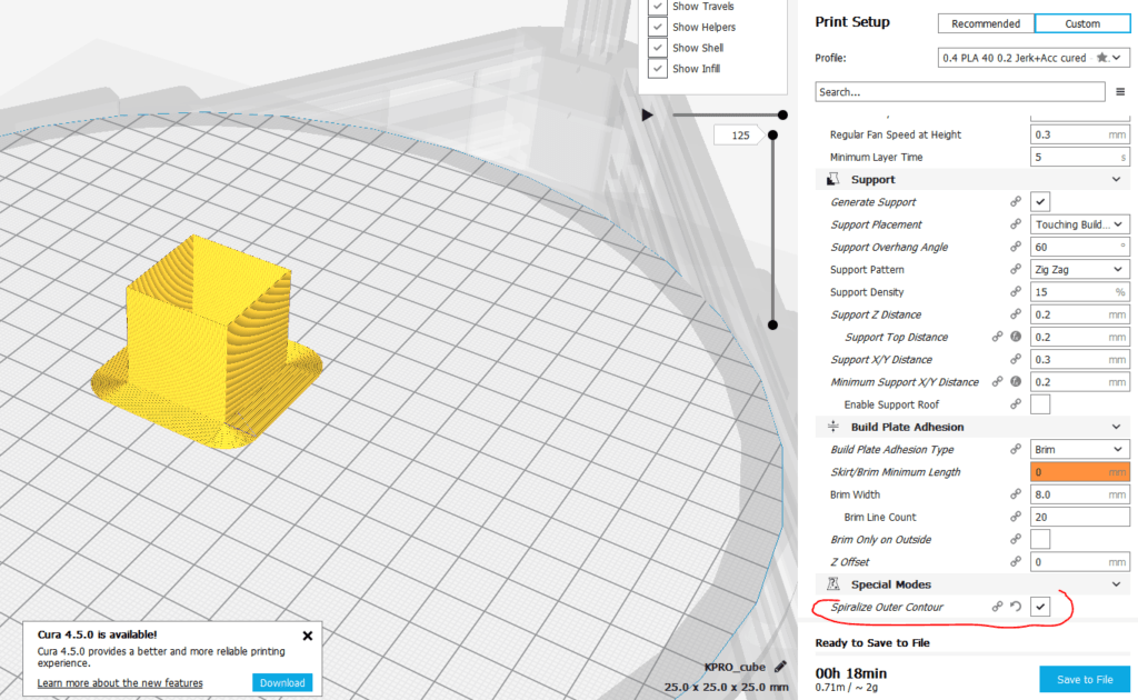 This is under Filament Settings -> Filament -> Diameter
In Simplify 3D, you set the filament diameter in the Other tab in the print process. This is under Edit Process Settings -> Other
My filament diameter values differ depending on the brand of filament i use. For Devil Design and Sunlu filament, i get a value of 1.74mm or 1.75mm.
On cheaper filament i used 1.73mm. But this value is specific to your filament and it can differ even between spools.
2. Print a Hollow Test Cube
The next step for flow rate calibration, is getting the current measurements of the walls. I say “walls” because it’s important to use two walls when calibrating the flow rate. This allows you to accurately get good measurements and it also includes the wall overlap value from the slicer.
Download the test cube and open the file in your favorite slicer. We need to slice the cube with the following values:
- Layer height – 0.
 2 mm
2 mm - Perimeters – 2
- Top layers – 0
- Bottom layers – 1
- Infill – 0%
- Speed – 50 mm/s (This value is recommended to be as close as possible to the usual printing speed).
- Temperature – 195C for PLA / 225C for PETG (value is set according to your filament specs).
- Cooling – 100% for PLA / 30% for PETG (value is set according to your filament specs).
If the cube is sliced properly, this is how it will show up in the print preview.
Start your print and go to the next step when finished.
3. Measure the Cube Walls
Now that the print is finished, we can start measuring the dimensions of the cube walls, to get the current values. Get the caliper and measure the wall thickness of each side of the cube.
As you can see, my wall width is really close to the ideal size. I used a 0.5 mm extrusion width, so when I measure two walls, the value is really close to the ideal 1 mm.
It’s really important to use the calipers correctly, and not apply to much pressure. Measure only the last few layers, to account for any wall imperfections and enter the values in the flow rate calculator below. The caliper should be placed close to the end of the wall, to account for any difference in the nozzle pressure.
Please clear your browser cache and refresh the page if the calculator does not show up.
4. Enter the new Flow Rate value in your slicer
Now that you have the new flow rate value calculated, go back in your slicer and save the new value. Use only the first two digits of your calculated flow rate.
In Cura, you need to edit the Flow value. This is represented as a percentage, so enter the value accordingly.
In Prusa Slicer, you need to edit the Extrusion Multiplier value.
In Simplify 3D, you need to edit the Extrusion Multiplier value.
In IdeaMaker, you need to edit the Flowrate under Primary Extruder -> Filament Settings -> Flowrate
It is recommended to repeat step 2 and 3, to make sure the new flow rate value is correct, and the measured wall size is close to the expected value.
Wrapping Up
Now that the flow rate calibration is completed, your prints should be more accurate, and the finish will be improved.
A few things to keep in mind:
- Don’t try to have perfect dimensions of the walls. Because of the nature of FDM printing, it’s close to impossible to have exact dimensions. Besides that, double digit values can be inaccurately measured. Just try to get as close as possible to the desired size.
- While flow calibration helps a lot, I don’t do this calibration for each spool of filament. I do it once for PLA / PETG / ABS / TPU and maybe do it once in a while, if I notice I get different results in my prints. While this is recommended, I prefer doing prints instead of continuously calibrate my printer.
If you are looking to calibrate your 3D printer further, then check out the 3D Printer Calibration Guide using IdeaMaker. For printer upgrades, you can also check out my Ultimate 3D Printer Upgrade Purchase Guide article where I go over a lot of hardware which can improve your print quality.
You can also join the 3DPrintBeginner Forum where there’s a dedicated category for FDM 3D printers.
Liked it?Consider supporting 3DPrintBeginner if this content helped. You can also join Patreon for exclusive perks! |
3D Printer Flow Rate Calibration – The Easy Way! – 3dprintscape.com
If your printer’s flow rate isn’t adjusted properly, you’ll end up with wall thicknesses that don’t match up to the preview in your slicing software. The same applies to the infill. If the flow rate is too high, the infill will be more dense than projected. If it’s too low, the infill may not be enough to support the part.
The flow rate setting, also known as the extrusion multiplier, is a setting that you can adjust to determine the amount of filament to be fed through. Different filaments and materials will feed through at different rates, which is why you should fine-tune the setting according to the type of filament. The default value is either 1 or 100%, depending on the slicer.
A high flow rate will lead to excessive filament use, while a low flow rate will reduce the print quality and structural integrity.
Before we calibrate the flow rate, it’s important to calibrate the E-Steps because that’s a part of what determines the amount of filament being fed through the extruder.
3D Printer E-Step Calibration – The Easy Way!
The default E-step value for an Ender 3 is 93, but if you’ve upgraded certain parts, like switching to direct drive, you’ll need to recalibrate to avoid over or under-extrusion. Here are the steps to follow on the Ender 3.
Prime the printer
- Go into “Temperature” and then “Nozzle”
- Now heat the nozzle to the temperature you normally print at, around 210 in my case.
- After the nozzle has heated, go back into the menu and then into Motion – Move Axis – Extruder – Move 10mm
- Turn the dial to feed 100mm of filament through the nozzle 10mm at a time.
- Make sure the filament is extruding from the nozzle at an even rate.
Here’s how to do it in touchscreen mode:
- Select “Nozzle” on the main screen and press the + symbol to increase the temperature to printing temps.
- Go back to the main menu and select “Extrude” and extrude filament until you see it’s coming through even. This is to prime the nozzle before testing.
Take measurements by hand
- Set your caliper to 120mm and tighten it in place.
- Put the shaft of the caliper into where the filament is feeding into the extruder.
- Pull the filament down onto the shaft to measure 120mm from the extruder. Mark the filament at 120mm with a permanent marker.
- From the menu, select Motion – Move Axis – Extruder – Extrude 10mm
- Now, the printer will attempt to pull 10mm of filament through every time you turn the dial.
- Don’t feed too much filament through at once. If you turn the dial up straight to 100mm, the gears might grind because they will try to pull too quickly.

- Once you’ve slowly fed 100mm through according to the display, it’s time to take physical measurements.
- Measure the distance from the extruder to the mark that you made previously and make a note of it, 27.02mm in my case.
- For optimal results, I like to run through the above steps two or three times before entering a new value into the E-step.
If you’re using the touchscreen mode and the extrude length automatically shows 5mm, make sure to manually set the extrusion amount again because the 5mm that it says it will do automatically is sometimes not correct. I’ve had a case where it extruded 100mm while showing 5mm on the display and I had to start the process again.
Once you have a few measurements, you can get the average of them to get a more accurate figure for calibration. Here’s my example:
(27.02 + 28.35mm + 27.93mm) / 3 = 27.76mm average.
Now let’s subtract the average length of 27.76mm from 120mm, which gives us 92.24mm. Considering we set 100mm of filament to go through on the control panel, we can now see that only 92. 24% of it actually made it through. This is the definition of under-extrusion and we need to bump up the value on the E-step to correct the problem. To determine how much we need to increase the value, divide the current value of 93 with the measured average value of 92.24mm and multiply it by 100 to get a percentage.
(93 / 92.24) * 100 = 100.82 This is the new E-step value.
- In the menu, go to Configuration – Advanced Settings – Steps/mm – E-Steps/mm
- Increase or decrease the E-step value according to the result you got with your measurements.
- Go back to “Configuration” and “Store Settings” to save the values.
Here’s how to get there in touchscreen mode:
- Menu – Settings – Machine – Perimeter – Steps per mm – E
- Insert the value up to 2 decimal places. 100.82mm in my case.
I cover this in more process in this article, 3D Printer E-step Calibration (Step-by-Step Guide), and this video I made.
Factors To Consider When Calibrating Flow Rate
If you print with abrasive filaments, the nozzle could be worn, giving it a slightly larger opening. So if you have a 0.4mm nozzle, you won’t be able to get a 0.4mm wall thickness. In this case, you need to calibrate the flow rate value downwards to counteract the wider nozzle bore.
For every type of filament you use, you’ll need to calibrate the flow rate accordingly. There’s no “one size fits all” value.
How To Calibrate 3D Printer Flow Rate
Calibrating the flow rate will involve printing a test cube and measuring its walls to identify the actual flow rate compared to the flow rate value.
With a 0.4mm nozzle and a flow rate of 1 or 100%, the thickness of a single wall should be 0.4mm. If the walls are thinner than 0.4mm, the flow rate needs to be increased. If the walls are thicker than 0.4mm, you’ll need to decrease the flow rate.
This can be a tedious process if you’re adjusting the value in small increments towards the desired thickness. You may end up printing a few cubes before getting the right numbers. But I have a simple method that will only require 2 or 3 cubes to be printed.
- Go into the slicer settings and verify the “flow” is 1 or 100%.
- Download this file from thingiverse.com. Test Cube
- Make sure the “wall thickness” of the test cube is the same as the nozzle diameter, 0.4mm in my case.
- Change the wall line count to 1. This should produce a 0.4mm wall on all four sides of the cube.
- Set the “infill density” and “top layers” to 0. (So that you can get the caliper in to measure the thickness)
- Print the test cube.
- Measure the walls with a caliper. (Calipers on amazon.com)
- Take note of the values. Mine were 4.8, 4.9, 4.8, and 4.7mm.
- Get the average thickness by adding all four sides and dividing by 4. In my case, it’s (0.48 + 0.49 + 0.48 + 0.47) / 4 = 0.48mm
- Now, divide the expected thickness by the average thickness.
 0.4 / 0.48 = 0.83mm
- For Cura users, multiply the 0.83 with 100 to get a percentage value and set the flow according to the result. 83% in my case. For slicers that use a numeric value, set the flow to the result without multiplying by 100, 0.83 in this example. Either way, you’ll be reducing the flow rate by 17% to counteract the over extrusion.
When Should You Adjust The Flow Rate?
You need to increase the flow rate if the printer is under-extruding and creating gaps or other defects in the print.
If you’re experiencing over-extrusion, decrease the flow rate to avoid defects caused by extra material. Defects may include, but are not limited to, thick ribbing on the exterior, sagging material, drooping supports, and lower print resolution.
When parts come out heavier than they should be according to the specifications, you might need to decrease the flow to save on materials.
If the walls of the printed part seem weaker and thinner than spec, increase the flow rate until you get the right thickness.
These are only some of the most common reasons you would adjust the flow rate. There are many defects that can appear because of an incorrect flow, so it’s best to calibrate it according to the specific type of filament you have before starting any extensive project.
Related Articles
- 3D Printer E-step Calibration (Step-by-Step Guide)
- OctoPrint Bed Level Visualizer – Complete Setup Guide!
- Glass Bed Upgrade – Complete Guide!
- Choosing the Right Infill Percentage for the Job
- 3D Printer Printing Too Thin – Let’s Fix It!
- Quick Guide to Change the Nozzle on a 3D Printer
In Summary
You need to calibrate the flow rate in your slicer to avoid over and under-extrusion. With an accurate flow rate, you’ll be able to print parts with higher quality. The formula I give in this article helps to get closer to the exact flow value required to achieve the perfect extrusion.
Remember to calibrate the E-steps before calibrating the flow rate for better results.
Here’s a video I made to explain the flow rate calibration process.
Make sure you check out our YouTube channel, and if you would like any additional details or have any questions, please leave a comment below or join us on Discord. If you liked this article and want to read others click here.
How to calibrate a 3D printer?・Cults
Since their invention, 3D printers have proven that printing many objects is much more efficient than conventional manufacturing techniques. However, calibration is required for optimal performance when printing 3D parts. Many 3D printer owners find this procedure tedious and time-consuming. However, it is much easier than it seems if you know the right tips on how to do it. Cults3D presents the various steps you need to follow in order to successfully calibrate your printer.
To ensure that the odds are in your favor during 3D printer calibration, certain precautions must be taken beforehand. Printer calibration is indeed an operation that requires rigor, but not only. You also need to make sure that your 3D printer is perfectly clean.
To easily calibrate your 3D printer, it is important to take the necessary time to clean the printer tray and existing nozzles. Calibration may be distorted if there is filament residue or print marks on the plate or nozzle. Cleaning the 3D printer nozzle allows to limit the effect of underextrusion and recurring problems when changing materials.
In addition to ensuring that the 3D printer calibration runs smoothly, be sure to check that the mounting screws are properly tightened. It happens that on some models of 3D printers, the screws loosen. So it's important to take a few minutes to make sure has no play between the various parts of your 3D printer. By doing so, you give yourself the best chance of getting your future prints right. If so, feel free to visit our website. You will find the best printable STL files to get started with your 3D printer in complete peace of mind.
Calibrating the 3D printer plate is the first step in this maintenance procedure. To ensure excellent print quality on a 3D printer, it must, like the following steps, be performed correctly. Plate calibration guarantees the success of the first print layer. To do this, you need to perfectly align the plane. In other words, the printer plate must be flat with respect to nozzle movements. It is also important to adjust the distance between the roller and the nozzle .
Calibration of the plate that supports the 3D printer can be manual or automatic. This procedure is slightly different depending on the printer model. Manual printer calibration is carried out using 4 screws located at the four corners of your machine's plate. The challenge is to find the optimal height ratio between these four screws for 3D printer plate alignment. To achieve this, make sure you repeat the following steps at least once in the center and four corners of the 3D printer tray.
First place a piece of paper between the nozzle and printer plate. Then move the tray up and down, being careful not to get paper stuck under the nozzle. Once the paper can be moved by light friction on the nozzle, you can move on to the next checkpoint . Some 3D printers, such as the Raise3D E2, have built-in automatic tray alignment systems.
The printing temperature of a 3D printer is of great importance for the manufacture of your parts. However, it is relatively complex and depends on the material you want to print. This is because the print temperature of standard PLA filament varies between different brands of 3D printers. The temperature range for printing is usually specified by each manufacturer on spools of filament. The temperature of the 3D printer plate is also an important parameter to consider. This allows eliminate the risk of re-peeling on some technical materials such as ABS thread.
The 3D printer's extruder is the part that spits out the hot filament. This may be due to two main problems. Over extrusion when the filament is used a lot, and under extrusion when the filament is used little. It is also necessary to take into account the thickness of the filament passing through the nozzle of the 3D printer. However, it is relatively easy to fix if it is out of order. To find out if your 3D printer is under or over extruding, you'll need a ruler, tape measure, or compass. Start by doing two marks 100 mm apart on the filament, then align the bottom mark with the top of the extruder. Then set the extrusion length to 100 in the 3D printer software and run the extrusion command.
Calibration of 3D printers also requires checking the accuracy of their measurements . To do this, you can use a piece of tape to mark two areas 100mm apart on the printer's base plate. On one of them, install the nozzle and ask the printer to move 100 mm in the desired direction. Then check that your device is exactly on the tape.
Measurements are rarely correct on the first try. Even a difference of tenths of a millimeter can greatly affect the quality of subsequent prints. 3D printers are precision machines and their motors must be calibrated to ensure accuracy. For the X and Y axes , adjust the values of M92 until you fix the offset at exactly 100mm.
A ruler must be used to calibrate the Z motor of 3D printers. Place the ruler vertically on the printing plate and move the Z axis by 100mm. Then, as in the case of engines X and Y, , change the values of M92 so that the travel is always 100 mm.
After these various steps, the calibration of your 3D printer is complete. However, to be sure, we recommend that you print test . For example, using a 3D printer, you can test the first layer. The first layer is the most important layer of your 3D printing. Unsurprisingly, problems with this layer usually create problems for the rest of your 3D printing.
Ultimately, calibrating your 3D printer is essential to ensure excellent print quality. The procedures are slightly different for different printer models. Therefore, this procedure may differ slightly. Don't be lazy consult the user manual of your 3D printer.
how to properly set up the table leveling sensor, semi-automatic auto-calibration test
Print quality on 3D printers depends on many factors. To ensure it, careful preparation of all units of the apparatus is necessary. Calibrating the 3D printer table is one of the most important preparatory steps.
What is table calibration and why is it needed?
For high-quality formation of a part from a filament on the desktop of a 3D printer, it is important to ensure a uniform distribution of mass over the surface. It is only possible with a perfectly horizontal level and an optimal gap between the table and the head nozzle. If the table has an uneven surface, then the gap will change in different work areas. The uniformity of the filament supply will be disturbed, which will lead to defects and deformation of the printed part.
Calibration consists of two main steps: leveling the surface over the entire working area and adjusting the vertical height of the head (Z-axis). Alignment can be done manually using the adjusting screws. More expensive printers have an automatic desktop calibration device. When adjusting vertically, the optimal gap between the nozzle and the table surface is set, which must maintain the specified value at any point in the working area.
Signs that the table is crooked and needs adjustment
The following signs indicate that the table needs to be calibrated:
- plastic does not stick to the surface, indicating an excessively thick layer;
- the bottom layer is peeled off the table during the subsequent application of the filament;
- gaps in the first layer or too thin lines;
- plastic builds up around the nozzle when printing the first layer;
- layer thickness and extrusion line vary markedly at different points on the surface;
- in some places the nozzle touches the already applied plastic;
- The filament comes out of the nozzle in a spaghetti pattern, i.
 e. it twists.
There may be other signs that indicate uneven application of a layer of plastic on the surface of the desktop.
Table Calibration Test
When manually leveling the table surface, the most commonly used point array test is Mesh Bed Leveling (MBL). The work surface is divided into a grid. In each of its nodes, the clearance along the Z axis is measured manually using a vernier caliper.
There are more accurate methods using test models. One of the simplest models involves printing circles in the center of the table and near all the adjustment screws. Printing is done in one layer with a thickness of 0.1–0.2 mm. When a difference in thickness is detected, it becomes clear which screw needs to be adjusted.
More complex test models require the printing of correct, but simple shapes. The hollow gauge cube 25 × 25 mm in size is popular. It allows you to evaluate the print quality of both the base and the walls.
Calibrating the 3D Printer on a Sheet of Paper
The most common way to calibrate the Z axis is to calibrate using a plain sheet of paper. The surface is meshed. A paper sheet is placed in each of its nodes between the nozzle and the table. The position of the extruder head is set so that the sheet can only be advanced with force. This coordinate is translated into a special G-command through the control computer program or through the printer menu. With manual calibration, it is simply recorded for future settings. This procedure is carried out at all grid nodes. Typically, the surface of a consumer printer is divided into a 3 × 3 grid, i.e. with 9nodes. You can increase the number of calibration points, but it is not recommended to create more than 49 points.
How to properly calibrate the 3D printer bed?
Different models of 3D printers may have individual features of adjustment and settings, but the general technique is typical for all devices. From the first time, it may seem to a beginner that the procedure is very complicated, but gradually it is brought to automaticity and does not cause problems. To eliminate errors, it is recommended that calibration be carried out at the same temperature to which it is heated during printing. For example, with ABS, you will have to warm up the table to 90-100°C. If during operation the surface is sealed with adhesive tape or cardboard, then they should be applied before starting the adjustment.
Table Leveling Tools
To calibrate the table yourself, you need to prepare the following set of tools and consumables:
- Calibration probe - thin plates with a precisely known thickness. You can use a strip from office paper 125-165 g/m 2 approx 10 x 4 cm.
- Wrench and screwdriver for adjusting screws depending on their design.
- Metal (preferably brass) brush and cotton cloth to clean the nozzle from adhering mass.
- Heat resistant gloves capable of protecting hands when heated to 110-120°C.
- Spatula, razor blades for scraping plastic off the table top.
- Laundry soap and cotton cloth for final cleaning from dirt and dust.
- Isoprene alcohol for thorough surface cleaning.
These tools and materials will help to carry out a complete cleaning of the working area and manual leveling of the printer table, to establish the required gap between the nozzle and the table.
Table preparation
The first step in the calibration is to prepare the table. First of all, it is necessary to thoroughly clean its surface. With the help of a spatula and razor blades, all remnants of adhering plastic from the previous print are carefully removed. If the table has a special coating (for example, PEI), then the blade cannot be used, as it may damage the protection.
After removing the plastic, the surface is thoroughly washed with dish soap. Warm water is used. If the surface material permits, cleaning can be done with isopropyl alcohol applied with a cloth or paper towel. After wet cleaning, the surface is wiped dry with a cotton cloth. When preparing the table, do not touch its surface with bare hands, so as not to leave grease stains.
An important parameter is the table temperature during calibration. It is important to take into account that the metal table significantly changes dimensions with temperature fluctuations, and therefore it is recommended to calibrate at the same temperature that is maintained in the operating mode. The need to preheat the table is indicated in the instructions for the device.
Auto Calibrate Table
In many 3D printers, auto calibration is based on Marlin firmware. The adjustment procedure begins by opening the firmware code in the Arduino Software (Arduino IDE). There are different versions of the program, but the actions for them are the same. The main settings are made in the Configuration.h tab:
- In the Z Probe Options section, support for manual mode is enabled.
- In Bed Leveling, the type of calibration by a matrix of points is selected (#define MESH_BED_LEVELING).
- In the Mesh section, calibration parameters are set: offset from the zone boundary, number of points along the X and Y axes, adjustment step and range of movement along the Z axis.
 It is recommended to use head movement commands.
After setting up the program, the calibration procedure itself is carried out in the following order:
- “Calibrate table” is selected in the printer menu.
- The "Autopark" mode is activated.
- Sets the drop height and Z of the table.
- The "Start" button is pressed, after which the movement of the table begins.
- A gap of about 0.5 mm is set. You can use a probe or a sheet of paper when calibrating.
Similar actions are carried out at all points along the X axis specified in the instructions for the firmware. All configured parameters are automatically saved in the printer, and therefore calibration is not required before each print run.
Manual calibration
Budget devices do not have automatic devices and table calibration is provided manually. It is carried out in this order:
- All adjusting screws are checked for smooth operation.
- The nozzle is cleaned of adhering mass.
- Each adjusting screw is loosened a few turns to increase the gap between the nozzle and the table.
- Calibration starts from one of the corners of the table. The nozzle of the extruder head is manually brought here. Use a feeler gauge or paper strip to set the optimum gap. Turn the adjusting screws carefully so as not to create excessive pressure on the probe. It can cause a response that can introduce an error.
- Similar actions are carried out in all corners. The level setting is checked at the center point. The clearance at all points must be the same.
When moving from one point to another, settings may fail. Therefore, it is necessary to check the previously established clearances. If they have changed, then everything is carried out in the second round. Sometimes it is necessary to carry out several circles of calibration. Next, the printer starts up and tests the correctness of the calibration.
Calibration sensor
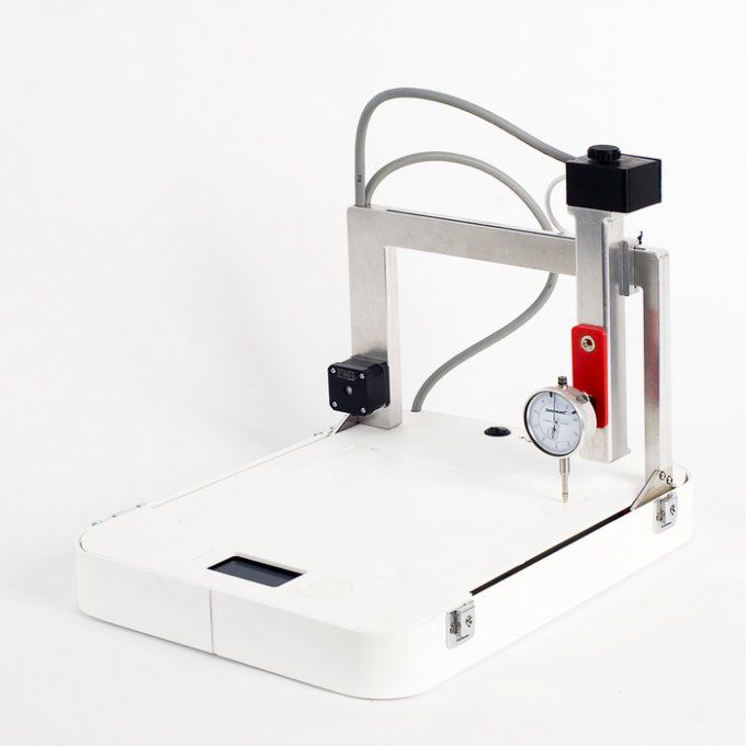
During automatic calibration, the printer has touch control of the table movement, and a contact sensor is installed at the level of the nozzle. It is automatically able to determine the exact distance to the working surface. Signals are sent to the motion control body, which provides a precisely set gap. In some printer designs, the extruder itself has a feedback encoder, which allows it to act as a sensor.
Manual calibration is checked for correctness by examining the first test print layer. The following options are possible:
- Gap between nozzle and table is too small. This is evidenced by such factors: a very thin layer, and in some places its complete absence; accumulation of mass on the nozzle; the mass is not squeezed out onto the table at all.
- Gap too large. Signs: poor adhesion to the bed, peeling on subsequent printing, twisting of the filament when exiting the nozzle.
In the first case, it is necessary to move the head up along the Z axis, and in the second, on the contrary, lower it down. Test models provide a more accurate check.
Calibrating the table
Automatic and semi-automatic calibration can be achieved in several ways. The most common options are:
- Through an external program. In this case, the special command G29 is used. So G29 S0 reads the current parameters of the points in memory; G29 S1 allows you to set the working body at the starting point; G29 S2 is for recording current information and moving the head to the next point. The M500 command allows you to enter all the necessary data into the machine's memory.
- Through the printer menu. The required items are selected in the Presets menu. The information needed for calibration appears on the display screen, the printer parks in a certain position. By clicking on the encoder, you can return the head to the starting point. When moving the encoder handle, the required clearance along the Z axis is set.
Important! The operator can choose the way he wants to control the auto-levelling.
How can I prevent table curvature?
Any user wants to calibrate the printer bed once and so that its evenness is maintained during multiple print starts. What leads to the need for frequent calibration? First of all, this is excessive vibration of the device during operation, which knocks down the adjustment of the adjusting screws. To eliminate this cause, proper installation of the printer and the use of anti-vibration pads is necessary.
The second common cause is frequent and significant changes in print temperatures. The metal table is very sensitive to temperature changes, which knocks down the settings. It is important to carry out calibration with preheating of the table.
Important! Violations of the operating rules of the device can affect the imbalance. To prevent curvature, you must strictly follow the instructions for the device.
There are many ways to avoid problems. The most effective is the installation of special sensors (for example, the Boultach sensor) that control changes in table parameters.