Diy metal powder 3d printer
3D Metal Printer | Hackaday
April 13, 2022 by Al Williams
We are used to dealing with warping when printing with thermoplastics like ABS, but metal printers suffer from this problem, too. The University of Michigan has a new technology, SmartScan, that promises to reduce this problem. You can see a video about the technique, below.
The idea is to develop a thermal model of the printed part before laser sintering and then move the laser in such a way that heat doesn’t accumulate. The video shows how engraving metal in the traditional way causes the metal to warp as the laser heats up areas. Using the SmartScan thermal model, they were able to reduce deformation by almost half.
Continue reading “Reducing Warping In Metal 3D Prints” →
Posted in 3d Printer hacksTagged 3D metal printer, 3d printingMarch 31, 2020 by Ted Yapo
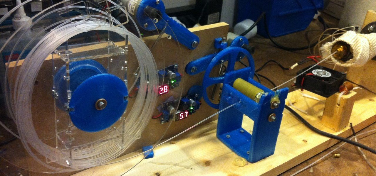
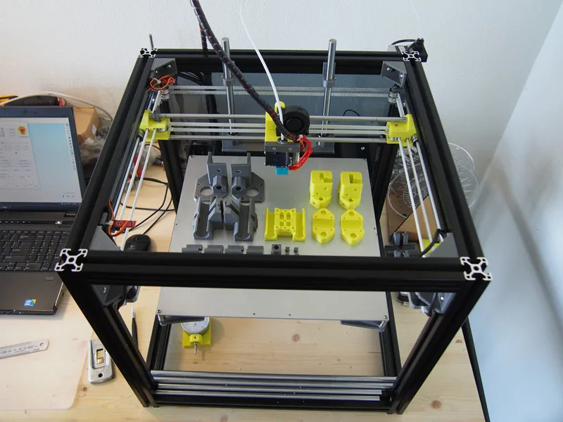
If you’ve seen both a fused filament fabrication (FFF) printer and a wire welder, you may have noticed that they work on a similar basic principle. Feedstock is supplied in filament form — aka wire — and melted to deposit on the work piece in order to build up either welds in the case of the welder, or 3D objects in the case of the printer. Of course, there are a number of difficulties that prevent you from simply substituting metal wire for your thermoplastic filament. But, it turns out these difficulties can be overcome with some serious effort. [Dominik Meffert] has done exactly this with his wire 3D printer project.
For his filament, [Dominik] chose standard welding wire, and has also experimented with stainless steel and flux-cored wires. Initially, he used a normal toothed gear as the mechanism in the stepper-driven cold end of his Bowden-tube extrusion mechanism, but found a standard wire feeder wheel from a welder worked better. This pinch-drive feeds the wire through a Bowden tube to the hot end.
In thermoplastic 3D printers, the material is melted in a chamber inside the hotend, then extruded through a nozzle to be deposited.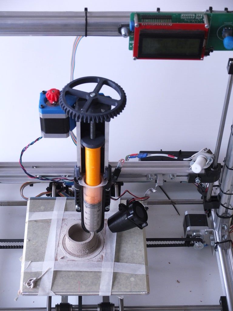 Instead of trying to duplicate this arrangement for the metal wire, [Dominik] used a modified microwave oven transformer (MOT) to generate the low-voltage/high-amperage required to heat the wire restively. The heating is controlled through a phase-fired rectifier power controller that modulates the power on the input of the transformer. Conveniently, this controller is connected to the cooling fan output of the 3D printer board, allowing any standard slicer software to generate g-code for the metal printer.
To allow the wire to heat and melt, there must be a complete circuit from the transformer secondary. A standard welding nozzle matching the wire diameter is used as the electrode on the hot end, while a metal build plate serves as the other electrode. As you can imagine, getting the build plate — and the first layer — right is quite tricky, even more so than with plastic printers. In this case, added complications involve the fact that the printed object must maintain good electrical continuity with the plate, must not end up solidly welded down, and the fact that the 1450 °C molten steel tends to warp the plate.
Considering all the issues that have to be solved to make this all work, we are very impressed with [Dominik’s] progress so far! Similar issues were solved years ago for the case of thermoplastic printers by a group of highly-motivated experimenters, and it’s great to see a similar thing starting to happen with metal printing, especially using simple, readily-available materials.
This isn’t the only approach to DIY metal printing, though. We saw one that used electron beam melting (EBM) not too long ago.
Thanks to [Krzysztof] for the tip!
Posted in 3d Printer hacksTagged 3D metal printer, 3d prining, weldingSeptember 17, 2018 by Mike Szczys
Last week I went to the International Manufacturing Technology Show (IMTS) and it was incredible. This is a toy store for machinists and showcases the best of industrial automation. But one of the coolest trends I found at the show are all the techniques used to 3D print in metal.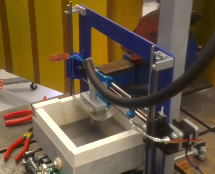 The best part is that many of the huge machines on display are actually running!
It’s probably better to refer to this as additive manufacturing, because the actual methods can be significantly different from your 3D printer. Below you’ll find examples of three different approaches to this process. I had a great interview with a company doing actual 3D printing in metal using a nozzle-based delivery often called cladding. There’s a demo video of powder layer printing using lasers. And a technique that uses binders as an intermediary step toward the final metal part. Let’s take a look!
Continue reading “3D Printing In Metal: The Laser And Metal Powder Printers We Saw At IMTS” →
Posted in 3d Printer hacks, Engineering, Hackaday Columns, Laser Hacks, SliderTagged 3D metal printer, cladding, directed energy deposition, IMTS, IMTS 2018, laser cladding, laser sinteringSeptember 14, 2018 by Al Williams
You normally think of HP as producing inkjet and laser printers.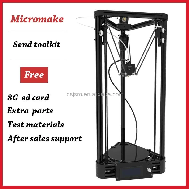 But they’ve been quietly building 3D printers aimed at commercial customers. Now they are moving out with metal printers called — predictably — the HP Metal Jet. The video (see below) is a little glitzy, but the basic idea is that print bars lay down powder on a 21-micron grid. A binding agent prints on the powder, presumably in a similar way to a conventional inkjet printer. A heat source then evaporates the liquid from the binder.
The process repeats for each layer until you remove the part and then sinter it using a third-party oven-like device. According to HP, their technique has more uniform material properties than fusing the powder on the bed with a laser. They also claim to be much faster than metal injection molding.
Continue reading “HP Rolls Out Metal 3D Printers” →
Posted in 3d Printer hacks, NewsTagged 3D metal printer, 3d printing, 3d printing metal, HPApril 12, 2018 by Brian McEvoy
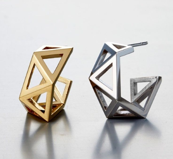
Machinists are expected to make functional items from stock material, at least hat’s the one-line job description even though it glosses over many important details. [Eclix] wanted a birthday gift for his girlfriend that wasn’t just jewelry, indeed he wanted jewelry made with his own hands. After all, nothing in his skillset prohibits him from making beautiful things. He admits there were mistakes, but in the end, he came up with a recipe for two pairs of earrings, one set with sapphires and one with diamonds.
He set the gems in sterling silver which was machined to have sockets the exact diameter and depth of the stones. The back end of the rods were machined down to form the post for the clutch making each earring a single piece of metal and a single gemstone. Maintaining a single piece also eliminates the need for welding or soldering which is messy according to the pictures.
This type of cross-discipline skill is one of the things that gives Hackaday its variety. In that regard, consider the art store for your hacking needs and don’t forget the humble library.
Posted in how-to, Tool Hacks, Wearable HacksTagged 3D metal printer, brass, diamond, gold, jewelry, posts, sapphire, scrolls, silverMay 24, 2016 by Bob Baddeley
Published only 3 days before our article on how it is high time for direct metal 3D printers, the folks at Harvard have mastered 3D metal printing in midair with no support (as well as time travel apparently). Because it hardens so quickly, support isn’t necessary, and curves, sharp angles, and sophisticated shapes are possible.
The material is silver nanoparticles extruded out of a nozzle, and shortly after leaving it is blasted with a carefully programmed laser that solidifies the material. The trick is that the laser can’t focus on the tip of the nozzle or else heat transfer would solidify the ink inside the nozzle and clog it. In the video you can see the flash from the laser following slightly behind. The extrusion diameter is thinner than a hair, so don’t expect to be building large structures with this yet.
If you want big metal 3D printing, you should probably stick to the welders attached to robotic arms.
Continue reading “3D Printing Metal In Mid Air” →
Posted in 3d Printer hacks, SliderTagged 3D metal printer, 3d prining, 3d printed metal, 3d printing with metal, Harvard University, metal, Wyss InstituteJanuary 14, 2016 by Elliot Williams
It seems backwards, but engineers from Northwestern University have made 3D printing metal easier (and eventually cheaper) by adding extra production steps to the procedure.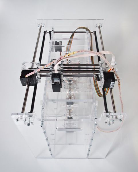 (Paper available in PDF).
Laser sintering works by laying down a thin layer of metal powder and then hitting it with a strong enough laser to sinter the particles together. (Sintering sticks the grains together without getting the metal hot enough to melt it.) The rapid local heating and cooling required to build up 3D objects expands and cools the metal, and can result in stresses inside the resulting object.
The Northwestern team still lays down layers of powder, but glues the layers together with a quick-drying polymer instead of fusing them with a laser. Once the full model is printed, they then sinter it in one piece in an oven.
3D-printed copper lattice. Credit: Ramille Shah and David DunandThe advantages of adding this extra step are higher printing speed — squirting the liquid out of syringe heads can be faster than fusing metal particles with a laser — and increased structural integrity because the whole model is heated and cooled at one time. A fringe benefit is that the model is still a bit flexible before firing, opening up possibilities for printing a flat model and then bending it into shape before sintering.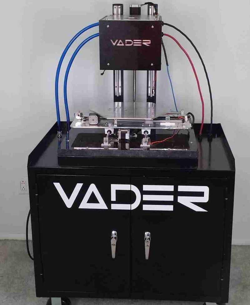
And if that weren’t enough, the team figured that they’d add a third step to the procedure to allow it to be used with rust (iron oxide) as the starting powder. They print the rust and polymer model, then un-rust the iron using hydrogen, and then fire it as before. Why rust? Do you know anything cheaper to use as a raw material?
What do you think? The basic idea may even be DIYable — glue metal particles together and heat them up enough to stick. Not in my microwave oven, though. We’d love to see a more energy-efficient 3D metal printer.
Thanks to [Joe] for the tip!
Posted in 3d Printer hacks, SliderTagged 3D metal printer, 3d printing, metal printing, rust, selective laser sintering, sls😲 Metal 3D Printing at home!
😲 Did you know that you can print 100% metal parts on your home 3D filament printer?
A hint: it’s not like making a mold to cast molten metal – much easier!
We show you how to print metal with your FDM printer and introduce you to all the 3D metal printing technologies that exist.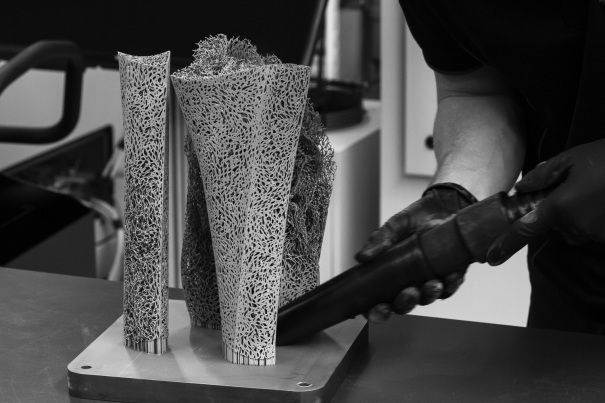
📖 What do you want to read?
Filament for printing metal parts
You may have noticed that some manufacturers sell filament with metal dust. These are materials that imitate the metal finish on your printed pieces.
But we are not talking about this, we are talking about filament that is printed in 3D and used to make 100% metallic printed parts.
What material is it? It is the BASF Ultrafuse filament from the German company BASF. It is a filament with a large amount of metallic dust that is printed with a conventional FDM 3D printer. After printing, the pieces have to follow a chemical washing and sintering process in an oven so that the metal powder is fused into a single solid metal piece.
Here is a video where you can see what results can be achieved with this type of 3D metal printing.
What is the filament made of? The content of the BASF Ultrafuse 316L filament is, as its name suggests, 316L stainless steel, a very popular steel used in applications where corrosion resistance is a critical feature, as it is more expensive and stronger than the most common stainless steel (304).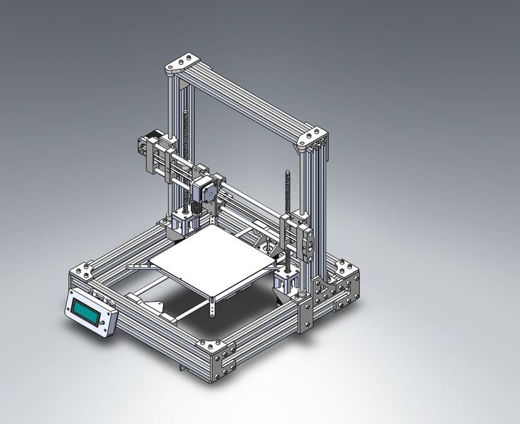
The filament coil contains 90% metal by mass; the rest of the material is the thermoplastic which makes it remain in thread form and flow through the printer extruder.
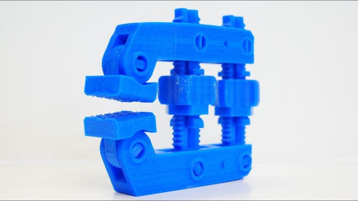
Examples of parts made with this filament
As you can see, the parts that go through the whole post-processing process have the characteristic lines of 3D layered printing and some filament sticking. The pieces can be sanded both in green (this is what the piece is called before it is washed and sintered) and in its final metallic form. They can also be polished, shot-blasted, etc.
Examples of metal parts printed with BASF Ultrafuse filamentThe post-processing of the metal filament
As we said, with this filament we need a post-processing to obtain the final metal part.
The post-processing is usually done in an external company. Usually when you buy the coil it includes in its price the post-processing of the parts you manufacture with it. The technologies for post-processing of powder metal and plastic parts already exist for MIM (Metal Injection Molding) manufacturing, so it is possible to find suppliers who focus on these phases.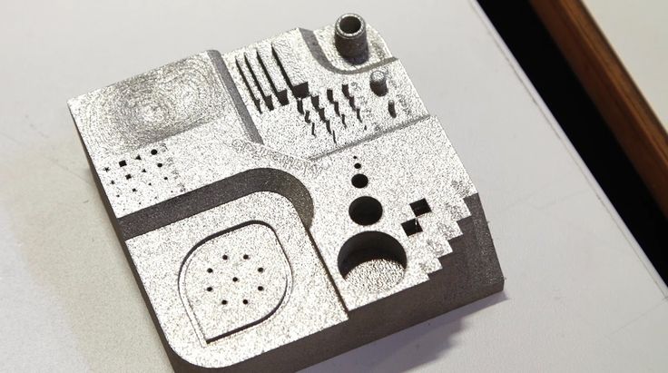
The process that the part goes through until it is a steel mass is as follows:
- Printing (green part). Printed on a conventional FFF printer with an abrasive resistant tip
- Washing/Debinding (brown part). The printed part is immersed in an atmosphere of vaporized nitric acid (HNO3) and heated to remove the plastic from the part so that only the metal dust remains. The result is the phase known as the brown part.
- Sintering. The brown part is placed in an oven where it is subjected to high temperatures without melting it so that the powder particles are completely fused and almost 100% desiccated. During this process the part shrinks, so it is necessary to print it with a margin that is established in the design process.
👉 How to print metal on your own printer
Now the most important question: can I use any printer to print it? Yes, you can print with conventional FDM desktop printers: Ultimaker, BCN Sigma… in 1. 75 and 3mm filament. The only thing you need is a steel nozzle to resist the abrasion of the metal filament.
These are the printing parameters of the BASF Ultrafuse 316L filament, judge for yourself:
How to print on metal? Just follow the manufacturer’s instructionsAnd how much does it cost? It’s starting to be distributed and can be found at Matterhackers for $465 a reel.
¿Do you want to try 3D metal printing?
We have not yet been able to get hold of a BASF Ultrafuse coil to test it, but we are very interested in starting to print metal parts. If you want to ask us for a quote for this or any other project, just leave us a message and we will help you make it happen:
Homemade metal 3D printer, but something went wrong / Sudo Null IT News
Hello everyone, my name is Sergey. In this article, we will talk about 3D printing with metal, more precisely, about my attempt to implement 3D printing with metal.
Very often, people who are interested in or engaged in any activity, no matter what, stumble upon something completely new and previously unknown to them, something that can help develop/improve their main activity. A similar situation happened to me.
Surfing the expanses of your Internet, I came across a wonderful technology for vacuum deposition of metals on various materials. On Habré there is an interesting article about this technology. In addition, on many other resources it was said that the evaporated metal moves towards the target in a straight line.
Many resources0003
And then I thought, what if I spray metal in the place I need, gradually increasing the thickness? I looked for information about whether someone did this - I did not find it.
Registered on a forum where sprayers gather together and began to disturb them with questions like: is it possible to build up a “film” with a thickness of 1 or more millimeters.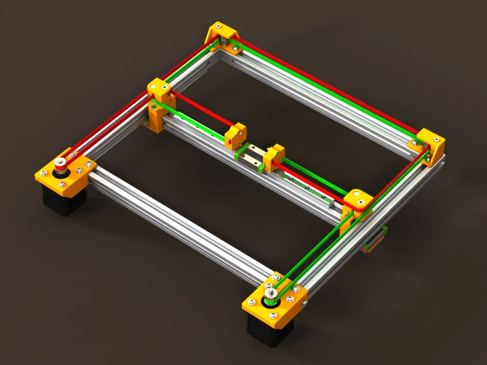 To which I caught a lot of misunderstanding what it was for, but received a positive answer.
General information received, you can begin to prepare for experiments.
It is known from various articles and documents that a vacuum of no more than 10⁻² Pa is needed. For comparison, the order of magnitude - the pressure that gives a household vacuum pump (Value and others) - about 4 Pa (measured value), i.e. pressure is 400 times greater than necessary. How to deal with it and what to do? To achieve low pressures, turbomolecular vacuum pumps are used, they work in parallel with the foreline pump and, literally by molecules, capture the remaining air from the chamber. The process is not fast. The pump looks like this.
We installed a pump, it pumps out air and everything seems to be fine, but how to find out the pressure? For this I chose an ionization vacuum gauge.
In fact, nothing else is needed, except for the chamber and evaporator. I did not find a ready-made affordable (in terms of finances) camera, therefore, I decided to make my own.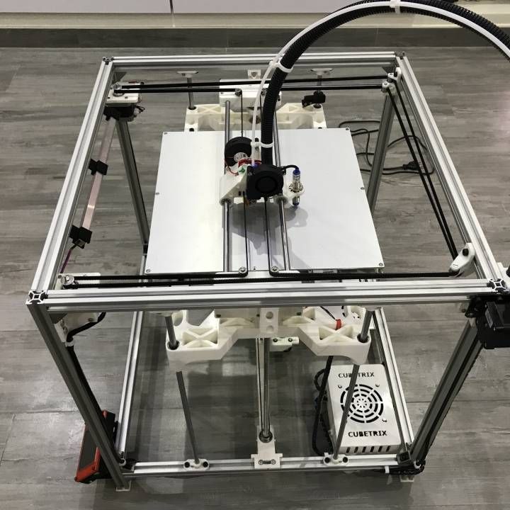 It is of a small volume (about 8-10 liters) in order for the air to be pumped out faster. Usually, the chambers have a spherical shape, in my case it is, on the contrary, elongated, in order to be able to set the “target” (the place where the metal is deposited) at different distances from the evaporator. In addition, the camera has a lot of flanges for connecting all kinds of inputs/outputs and sensors. I modeled the camera in a well-known CAD program, drew drawings and transferred it to production.
Current leads and conductors I made from a brass bar and a brass rod, bought on the local market. (Juno, who is from St. Petersburg).
In the photo below, a tungsten boat is fixed between two conductors.
The bottom part looks like this. The photo shows the cooling tubes of the current leads. Subsequently, I abandoned them, due to the simplification of the system.
Assembling the camera did not take much effort and complexity. It is much more difficult to achieve vacuum retention in this chamber. To do this, I polished the flanges and all mating surfaces to avoid the slightest leakage through the rubber seal (in the photo below, I processed only the top flange).
As it turned out later, the weld is not airtight at all (meaning for low vacuum). I, out of inexperience, assumed that by pumping a pressure of 300 kPa into the chamber and immersing it in a bath of water, I would carefully find all the leaks and eliminate them. Yes, at the first stage I did just that, but the pressure in the chamber did not fall below 10-2 Pa, there were leaks. Interestingly, before the start of the test, at a pressure in the chamber of 300 kPa, bubbles emerged from the welds with an intensity of approximately 1 bubble (diameter 2-3 mm) in 30-40 seconds. And those were big losses that I eliminated. But what to do with minimal vacuum losses that cannot be tracked in "kitchen" conditions?
The solution was close. To do this, all you need is a mass spectrometer.
The idea is simple – the investigated chamber or container is connected to the vacuum chamber of the spectrometer. Air is pumped out, on the graph they look for extraneous peaks of any gases. After that, helium is supplied locally, to the places of possible leakage. It is helium, because its penetrating power is higher and the helium peak can be easily tracked on the spectrum. As soon as helium enters the chamber through a micro-hole, it is immediately visible on the spectrum.
I drove twice and looked for leaks twice. Now the chamber with the installed pump is hermetic and it is possible to carry out experiments further, having previously assembled all the components of the system on the rack.
General view of the incredible installation.
Starting up the plant and checking it comes down to maintaining the lowest possible pressure. The foreline pump is started first.
The pressure after the operation of the foreline pump can be seen in the picture below.
After the pressure is established (does not change). You can launch "heavy artillery" - a turbomolecular pump. It reduces the pressure by another 3 orders of magnitude.
The time has come for experiments, what I have been going for so long and what I have been waiting for so long.
First experiment.
Place a small amount of silver into the boat fixed between the conductors. Above the boat I install a steam conduit - a soldered tin cylinder, which, as I thought, should limit the spread of metal through the chamber. Above the steam conduit there is a lid with a hole of 2 mm, behind the lid there is a target on which the metal should condense. It is a pity that there are no photos left, but the vacuum chamber was completely dusty. There was not a single place where there was no applied layer of metal. In the photo below, it’s not a different planet at all, but silver sprayed onto the inner surface of the wall.
Second experiment.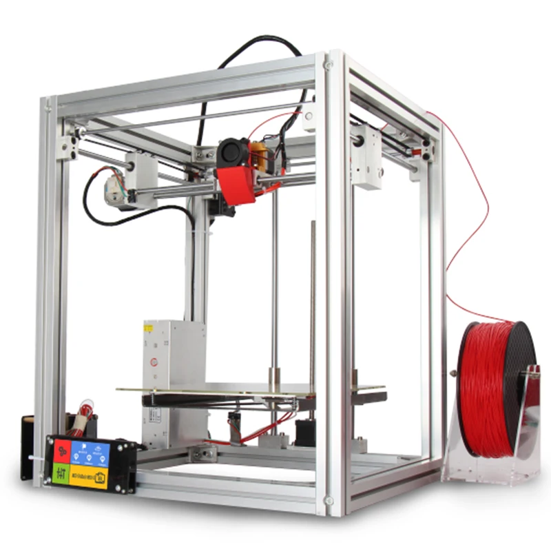
I thought it was because of the large gaps between the boat and the steam line. The solution was born immediately and quickly. I took two boats and combined them so that a shell was obtained. I placed silver inside, and cut a hole with a diameter of 2 mm in the upper half.
And he began to heat up the whole thing. But, I did not take into account the rigidity of the boats and the rigidity of the current leads. The shells parted a little and a gap formed between them, through which steam also flew in all directions.
As a result - spraying in the entire volume of the chamber. In the photo below there is a viewing window, the boat in which was slightly above half, but the window was completely dusty.
Third experiment.
After a little thought and grief, I thought that the container with the evaporated metal should be airtight and with only one outlet, but how and what to make it. From tungsten - very expensive and difficult to process.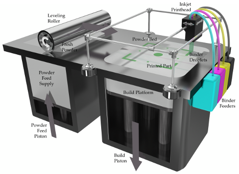 The way out has been found! Graphite is an excellent material for making a crucible, let's call it that. On the ad site, I found an ad for the sale of graphite bars from the contact whiskers of a trolleybus, cut out a bar with a hole in the center and made a cover for it. In the photo below - just a bar with a hole for the material (without a cover).
And in this photo already in the chamber with the lid installed (the hole in the lid is 1 mm in diameter).
Under the spoiler are a few photos with a short period of time, from which you can see how dusty the viewing window is.
Loss of transparency
It is obvious that in this case, too, there was no success, to my great regret. All three experiments were carried out with a gradual increase in temperature from the state when evaporation does not occur.
A small video in which the information is presented in a slightly different way, in a different form and volume.
Video link
www.youtube.com/watch?v=4yWQOWIG1qw
Unfortunately, it was not possible to get what was intended, but, on the other hand, invaluable experience was gained in the design and manufacture of vacuum equipment. Most of this experience I have shared with you and I would be very grateful if you express your opinion on this issue.
Thank you all and good luck.
3D metal laser printer: do-it-yourself metal 3D printer
Metal 3D printing is increasingly competing with traditional production methods. 3D printers can print metal nuts and wrenches, screws, bolts, car and aircraft parts, decorative items, cutlery and almost any product whose dimensions correspond to the dimensions of the printed surface of the printer. Larger objects can be printed as separate components and then assembled together.
The main problem of metal 3D printing is the high cost of consumables. Many products are still easier and more profitable to manufacture using traditional production methods. This article will review the process of metal 3D printing using SLM and DLMS technologies, provide an overview of the most popular printers, and assess the prospects of technology in industry and at home.
SLM vs DMLS: What's the difference?
Both of these technologies are actively used today for metal 3D printing. SLM involves selective laser melting of metal powder, while DMLS involves direct laser sintering of metal. In both cases, a laser is used to selectively melt metal powder grains, bind these grains together and create products in layers.
The difference between the technologies is:
- Metal powder is melted in SLM.
- DLMS uses lower temperatures so the metal does not liquefy. Powder particles simply sinter together.
Both technologies are protected by patents.
How does metal 3D printing work?
Metal 3D printing today requires an impressive amount of money. The cost of printers is measured in hundreds of thousands of dollars, and to this we must also add the cost of maintaining and maintaining them, purchasing consumables, training employees and remunerating them.
At the same time, these costs are offset by the efficiency of the production process. Thus, traditional production methods in the aviation industry lead to the fact that up to 90% of raw materials turn into waste. With 3D printing, no more than 5% of the material is sent to waste. Unused powder is sifted, mixed with new and reused for printing.
WARNING : Support area elements are usually waste.
The power consumption of 3D printers is much lower than traditional equipment. The mass of printed components is half that of traditional counterparts. This is especially important for the aviation and space industries, as it saves millions of dollars in aircraft fuel.
Using 3D technology, you can print the following products:
How a metal 3D printer works
SLM and 9DMLS 3D printers print using the same algorithm:
3 Inside the build chamber, argon or another inert gas is launched so that the metal powder does not oxidize so much.
The finished object will be powder coated and secured to the work surface with supports. Supports are made of the same material as the object itself - otherwise they can be distorted or deformed under the influence of high temperatures.
The build chamber is allowed to cool to room temperature, the remaining powder is manually removed. The printed object is first heat treated to remove residual stresses and then the supports are removed. Once separated from the print platform, the parts are ready for use.
Key features SLM & DMLS
In SLM devices, the laser melts each layer of metal powder individually. Temperatures change drastically, which causes internal stresses in the parts. This may adversely affect the quality of the product, although it will in any case be higher than when casting. Products printed on SLM printers are superior to DLMS counterparts in terms of safety margin and solidity.
When working with DLMS technology, internal stresses are not created, so the quality of products is incommensurably higher than that of analogues made by stamping or casting. This is especially required for the aerospace and automotive industries, since the components used in them must be extremely durable.
Printer parameters
The parameters of metal 3D printers are usually:
- The layer thickness ranges from 20 µm to 50 µm.
- Dimensional accuracy is approximately ± 0.1 mm.
- The average printable area is 250 mm × 150 mm × 150 mm.

Devices are usually sold pre-configured so that the user does not have to change anything.
Adhesion between coats
Products printed on SLM and DMLS printers are almost identical in their isotropic thermal and mechanical properties. They are solid, their internal porosity does not exceed 0.5%. Compared to conventionally manufactured parts, these parts are usually stronger and more flexible, but are more prone to fatigue.
Support area and part orientation
Support for metal parts in 3D printing is a must, as their processing temperatures are extremely high. To build such supports, a lattice structure is usually used.
In the production of metal objects, support takes on the following tasks:
- to provide the next layer with a secure platform;
- fix the element to the build platform and prevent its deformation;
- remove heat from the product and allow it to cool at a controlled rate.
To minimize the risk of deformation and increase strength in critical directions, products are usually oriented at an angle. Because of this, the printing time and material consumption increase, the cost of production increases, and the area of \u200b\u200bsupport required expands.
CAUTION : To avoid warping, it is acceptable to use random random scan patterns. Such a sequence of laser passage through the sections of the layers will remove the residual stresses remaining in a particular direction.
Simulations are used to predict product behavior during printing. Continuous optimization algorithms can be used to produce lightweight parts and improve their performance. These algorithms also reduce the risk of deformation and reduce the required support area.
Hollow sections and lightweight constructions
Removing support areas for metal parts requires considerable effort, so hollow sections are avoided. Instead, products are designed to have a core and a shell. They are treated with a laser at different powers, with different scanning speeds.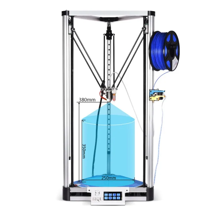 As a result, different areas of parts have different properties.
This approach is particularly useful for the production of objects with large solid sections. The risk of their deformation is minimized, the printing time is reduced. The finished objects are exceptionally stable and their surfaces are extremely high quality.
WARNING : To reduce the mass of the object, metal 3D printing often uses a lattice structure.
SLM and DMLS consumables
These technologies print on aluminum, titanium, inconel, cobalt chromium and other metals and metal alloys. The scope of powders of these metals is extremely wide: from medicine to the aerospace industry. Silver, gold, palladium and platinum are printed mainly in the jewelry industry, these materials are not in great demand outside of it.
WARNING : prices for metal powders remain high and can be in the region of $400 per kg. Therefore, today in 3D it is advantageous to print primarily small metal parts that are too difficult or expensive to create using traditional methods.
Cobalt-chromium or nickel superalloys are extremely difficult to work with conventional methods. 3D printers, on the other hand, create products with an almost clean surface from such a powder, which can then be refined using more familiar methods.
Post-processing
Parts are post-processed to improve their accuracy, mechanical properties and appearance. Support areas are removed from them, the remnants of the powder are cleaned off, and then subjected to thermal firing. During heat treatment, residual stresses are removed from the products.
If the product needs to be given a complex geometric shape, to create threads or holes on it, CNC machines are used for this. To improve surface quality and increase fatigue strength, products are pressure treated, metallized, polished and micromachined.
Metal 3D Printer Overview
Below are the technical specifications and brief descriptions of the four most used metal 3D printers in industrial production.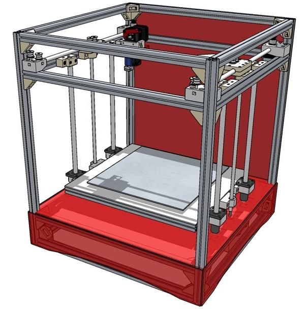 The exact price is given for one model only, since prices for such units are usually announced upon request. In any case, we are talking about hundreds of thousands of dollars.
HP Metal Jet
MJF powder sintering technology delivers up to twice the printing speed of laser technology. Metal powder is applied to the working surface of the device, leveled and filled with a printing compound according to the shape of the part, which binds the powder grains together. Each layer is fixed at a high temperature, then the remaining powder is removed from the working surface and the entire object is sintered.
HP Metal Jet 3D Printer
- Material Metal powder
- Print resolution 1200x1200 dpi
- platform type Stainless steel
- Working chamber area 430x320x200 mm
Go to product
The service life of the device, according to the manufacturer, is at least 100,000 parts.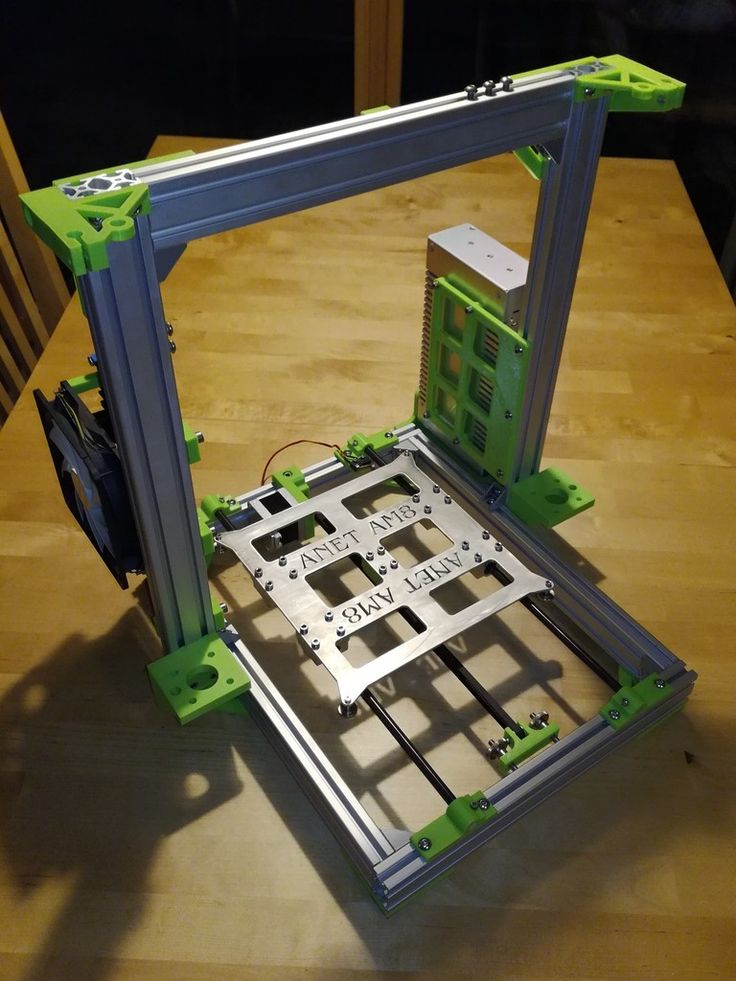 In a spacious workspace, you can produce several objects in one go, and their height can be different. The products printed on the printer comply with the international ASTM standard. Density index after sintering exceeds 93%.
Farsoon FS121M
This model features high speed and extreme construction accuracy, which provide an individualized laser scanning algorithm. For inert gas, a supply and filtration system has been developed, which increases the safety of work and the quality of manufactured objects. The software of the device was created in open source and is constantly being improved. Due to this, the user gets maximum access to all configurable printer settings.
- Dimensions, mm 780×1000×1700
- Software FarsoonMakeStar
- Manufacturer country US
- Weight, kg 1000
- Laser spot diameter 40~200 µm
- Shielding gas Argon / Nitrogen
- Laser power 200 W
- Seal SLM
- Laser type Yb fiber laser
- File format STL
- Working chamber area 120×120×100 mm
- Speed 5 cm3/h
- Layer thickness from 20 µm
- Scan speed 15.
2 m/s
Go to product
Russian SLM 250
Russian The Russian-made SLM 250 from 3DSLA is compatible with both native and third-party consumables. If necessary, the manufacturer is ready to create custom-made powders. The device prints with powders with fractions of no more than 60 microns, fusing them layer by layer with a laser in the presence of an inert gas. Triangulatica's own software was developed for the printer, which not only processes the loaded models and generates support for them, but also controls all phases of the printing process (laser power, inert gas state, layer thickness, and so on). If desired, the device can be supplemented with a powder sifting station and a fractional division unit for it, a layer-by-layer video control system for printing with an archive for data storage, a shielding gas generator with a purity of up to 99.99% (this figure is given for nitrogen). If you plan to use not the entire printer platform at once, it would be wise to purchase a powder saving module as well.
3D printer SLM 280 2.0
- File formats STL
- Dimensions, mm 2600 x 1200 x 2700
- Software SLM AutoFabMC
- Manufacturer country Germany
- Weight, kg 1300
- Laser spot diameter 80 - 115 µm
- Minimum wall thickness 150 µm
- Laser power 1x400/2x400/1x700/2x700/1x700 + 1x1000 W
- Seal SLM
- Performance 55 cm³/h
- Shielding gas consumption during construction, l/min.
Ar 2.5
- Shielding gas consumption during purge (start of operation), l Ar 70 l/min
- Laser type IPG fiber
- Working chamber area 280 x 280 x 365 mm
- Layer thickness from 20 µm
- Display yes
- Interfaces Ethernet 10/100/1000
- Scan speed 10 m/s
Go to product
Concept Laser X line 2000R
- Technology: LC
- Print surface dimensions: 800 mm x 400 mm x 500 mm
- Weight: 8000 kg
- Layer thickness from 2 µm0160
The abbreviation LC stands for LaserCusing and is the manufacturer's own design. This technology is close to laser sintering, but is carried out using high power fiber lasers. Thus, there is no sintering, but a complete fusion of powder grains to a homogeneous mass. This allows you to create products of the most complex geometry with outstanding technical characteristics. The device is equipped with a vacuum unit and can also work with reactive materials (eg titanium). Marcam AutoFab M2 software allows you to create models of jewelry and dental products for printing, and 3Shape CAMbridge automates the production of metal orthopedic structures.
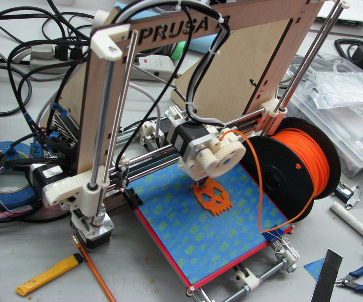
Do-it-yourself: metal 3D printer for the home
Outside the production environment, it is better to print not with metal, but with plastic filament with the addition of metal particles, such as bronze. For this, an FDM printer is suitable, whose cost is significantly lower than that of machines for printing with metals. FDM devices do not need to be heated to such high temperatures as industrial metal printers, the level of noise and unpleasant smell from them is much lower. In this way it is very convenient to print interior objects, household items and jewelry.
Products printed from plastic filament with metal particles look and feel indistinguishable from metal counterparts, and also have a comparable mass. Unlike metal, they will never rust. For their manufacture, it is not necessary to install a heated table on the printer, and when cooled, such products will give minimal shrinkage. However, it requires post-processing in the form of grinding and polishing, and the nozzle temperature and filament feed rate must be fine-tuned. In addition, metal particle filaments are extremely abrasive, which accelerates nozzle wear.
WARNING : It is not recommended to create objects with plastic filament using metal that will come into contact with food.
3D printing with metal powder allows you to create products with much more complex geometries than analogues produced by traditional methods. The finished product has excellent physical characteristics, even if it was made from superalloys that are difficult to process traditionally.