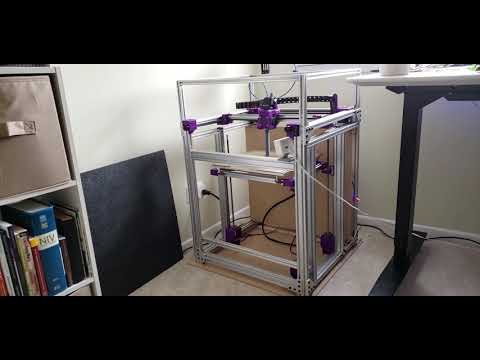
Requirements for 3d printing
3D Printing Basics 8 – Requirements – Tom's 3D printing guides and reviews
In this video, we’ll look at the things you should consider when thinking about 3D printing something – can you even print the part you want to make, what should your environment look like where you print stuff and what do you need for equipment and tools to work with the machine and the final prints.
What can you print?
Okay, let’s get right into it and start with the models themselves. Over the years, 3D printers have become a lot better when it comes to what they can and can’t print, but there are still a few limitations and best practices. To understand where those come from, you need to keep in mind how these machines work and how that immediately affects the output they produce. And thankfully, when you run into a limitation you can usually just watch the print and you’ll see what is going wrong.
Small Details
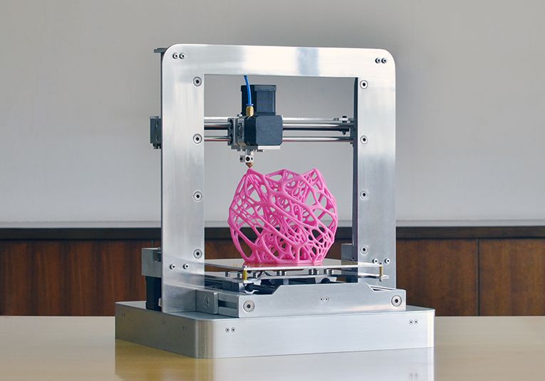
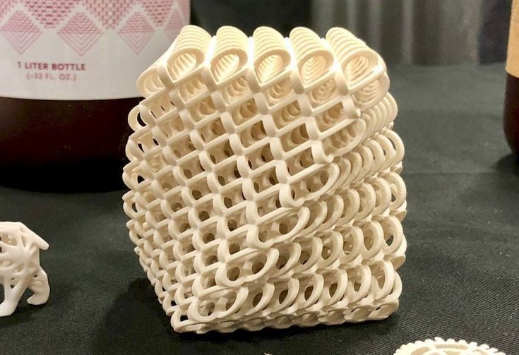
So for a filament printer to work, it needs to first, heat and extrude filament through a nozzle. That nozzle has a set orifice size and because molten plastic is highly viscous, it can’t immediately start and stop extruding, there’s always a bit of a ramp-up and ramp-down. Also, as the plastic comes out of the nozzle, and as it cools down to ambient temperature it shrinks and contracts. So a few things that result from that: First, it’s really hard to reproduce details that are basically just little dots of filament or similarly small features, like thin arms of a miniature character or raised text that’s going to be printed on its own layer.
For text, it’s almost always better to emboss it instead of raising it, and when it comes to fine features, anything that has a wall thickness of two to four times the nozzle size is usually going to print just fine. If it’s a consistent, thin wall, going down to 1x the nozzle diameter can work, too, depending on your slicer and its setup, but especially with softer filaments, long, super-thin walls can become quite floppy and end up with a wavy structure.
Warping
Now, because of how plastic shrinks as it cools, you get a few effects that can warp your prints out of shape. This is not so much an issue when you’re just printing PLA, but as materials get more temperature-resistant, its tendency to warp and to lift off the printbed during the print also increases. Models that have a strong core, but only little contact area towards its edges are most likely to have issues here.
Curling
For the next one that’s temperature-related, curling, we should probably look into overhangs first.
Curling usually happens on an overhang, and overhangs themselves are the main consideration when determining if a part can be printed or not. As a filament printer lays down a line of material, it will always need something to attach it to. Normally, that’s the layer underneath. And of course, there needs to be some overlap between those two so that the new layer is supported properly. In practice, that means that there’s a limit to what angle the underside of a part can have before it will start to cause issues – and that angle is the overhang angle. The classic and still safe rule used to be 45° from horizontal, but as the hardware and software have improved, you can now usually do 30° without too much trouble. Something you can definitely not do is to have a negative angle where, so as you trace a path from the printbed up, your part starts dipping down again. As the print gets built up, that spot down there would be printed onto thin air, which obviously isn’t going to work, so you’d need to use support material right there.
So back to curling, basically, that’s what you get when the overhang is too steep for your combination of printer, filament, and print settings. It’s most obvious at edges where two overhanging areas meet and create a steeper compound overhang.
Bridging
One really cool thing that printers can do where you can cheat on all this a bit is bridging, where the printer can stretch a single line of material over a gap, but for that to work, the start and endpoint need to be at the exact same height, aka. on the same layer, so the underside needs to be perfectly horizontal.
Now, of course, we could go into a lot more detail here with design rules, etc., but a lot of it comes down to just actually trying different things and seeing what works and what doesn’t – all these “rules” can be stretched a lot depending on how exactly your models are made.
Environment
So when it comes to the environment that you’re printing in, that one goes both ways. First, the things the printer itself needs to work well. And there, it’s really not much. You need a flat table to sit the printer on and an overall not-too-cold or drafty and not-too-humid atmosphere. A “normal” room is usually fine, after all, that’s what these machines and materials are made for, but if you have an air conditioning vent blowing directly at the printer or you’re living in a particularly hot and humid area, those things might become an issue. Too low of a temperature is easy to fix, though, just drop your printer in a box and it will heat itself up enough to work even with the higher-temperature filaments.
For the other requirements about the workspace, I guess I should mention that printers with a moving bed will extend past their “packing size”, so a deep work surface is highly recommended, 80 cm or 4 link deep gives you plenty of space.
And when it comes to actual workshop use, try to keep it in a space where it won’t get dust, wood, metal shaving, or grinder sparks thrown at it.
One thing that I rarely think about because it’s not really an issue here is power outages, so if you’re doing longer prints and your printer doesn’t have a power panic feature, you might want to look into getting a UPS to plug your printer into.
Immisions
Now, if you look at it the other way around, some details might make printing more comfortable not for the printer, but for you. I’m talking imissions here, of which you’ve got noise and vibrations as well as smell and fumes. Let’s start with noise. And printers vary a lot between different models in how exactly they sound. You’ve got nearly silent printers, then you’ve got somewhere the fans are the loudest thing, then you have some that cause vibrations and some that emit a high-pitched whine, driving gen Y and Z crazy as well your cats and dogs.
Vibrations are fairly easy to mitigate by using a weighted plate and a piece of foam to rest your printer on; for other noise, again, you can use a box, but for a lot of printers, with that, I still wouldn’t want to have it sitting next to me on my desk.
And that’s not just because of noise, but also, because of smell and the particles printers emit. There is some research that suggests that filament printers emit a considerable amount of particles, even when printing PLA. I don’t know how harmful exactly those particles are, but filaments like PLA, ABS and Nylons are some that you can definitely smell and their fragrance isn’t always particularly pleasant. So between the noise and the smell, I’ve relegated my working printers to their own little room. Right now it doesn’t have any ventilation in there, it should, but it’s got a door that I can close and not worry about it.
I’m also keeping all my filaments in there and the moisture-sensitive ones in dryboxes, which makes a massive difference in just being able to reliably print stuff.
Safety
Now, I’ve got this OSB box in here with an old MK2 and a multi-material 1 on it, so that it’s always ready to rock. In the video when I set this thing up some of you pointed out that using wood as a box might be an issue because it burns. Which is a somewhat valid point. Now, wood doesn’t catch fire as easily as one might think, and printers almost never fail so badly that they will burn up, but some less reputable brands have had a handful of their printers more or less spontaneously ignite themselves, and because they were using a plastic frame, that caught on fire and as a result, a couple of houses almost burnt down. Now, again, that’s an extremely rare occurrence, and for example, on the MK3 I know that there are checks and extra sensors in place that prevent that exact failure mode, but, still, these are machines that contain relatively high-power heaters and it doesn’t hurt to be safe about it. At the very least, have a smoke detector correctly mounted near your printer and make sure you can actually hear it when goes off, you can get wireless ones that will trigger all the other alarms in the house if one goes off, but also, try to not keep any highly flammable materials near your printer.
If you’re worried for example about this wooden box, have a look at building code and for example, use a sheet of drywall on the inside to create a fire barrier.
It also goes without saying that it’s not exactly recommended to leave the printer unattended for long periods of time, like, even though I trust most of my printers, I wouldn’t start a two-week print and then leave the printer while I go on vacation.
As far as the printer itself throwing stuff around, you will quite often find these priming lines scattered around the printer as well as that filament change extrusion blob and if you’re printing with support material, snapping that off can get it to fly pretty far. So just maybe avoid carpet floors, because those bits can stay stuck in there.
Lastly, if you’re using a spray-on bed adhesive, always apply that outside of the printer, so take out the glass or metal bed and spray that on away from the printer and away from any other surfaces that you don’t want to get covered in, well, basically hairspray.
Tools
Now, what tools should you have to work on and with a 3D printer? Really, it’s not much. Many printers actually include things like a hex key set, needle-nose pliers, and maybe even some of the common size wrenches that you’d need for, for example, a nozzle swap on the hotend. For that, one of these little torque wrenches does come in extremely handy if you don’t quite have the feel yet for how tight a hotend should be assembled, because if you give that too much oomph, it’s really easy to damage it. But back to the basic tool, as I said, hex keys, some pliers, a screwdriver set, wrenches… Basic hand tools, really; for maintenance, the most you’ll likely going to do is maybe retightening a few things, but even if you decide to dive in a bit deeper and get modifying, these tools should take you a long way. Maybe one more 3D-printer specific tool if you don’t have a flex bed: Some way to remove prints, either a thin, sharpened spatula.
I’ve also got this strip of steel that has a really nice edge on it, I forgot who exactly I got it from, but it’s thin enough to slide under a print and just basically shear off the adhesion without just pulling up, which would risk pulling up the bed surface with it. So if you’re looking for a print removal tool, look for something you can really slide under your part and not something like a chisel where it gets real thick real quick.
Let’s recap
The most basic requirements for printable designs are to avoid details smaller than two times your printer’s nozzle size; and for large parts printed with high-temperature filaments, warping might become an issue. For all prints, overhangs should stay over 30° from horizontal.
Provide a flat, stable and large enough surface for your printer and make sure temperature and humidity stay in a range that you would consider comfortable. If you’re happy, your printer is, too.
Be aware of noise, smell and particle emissions of your printer and take reasonable precautions against fire hazards.
And lastly, if you have some basics tools, you’re all set on that front.
So that’s it for this one, in the next video, we’ll look at common print issues and solutions for them, until then, thank you for watching, make sure to get subscribed, keep on making, and I’ll see you later.
💙 Enjoying the videos? Support my work on Patreon!
3D Printing Basics – Episodes
- What is a 3D printer?
- Choosing a machine
- Resin printers
- Filament printer parts and maintenance
- Acquiring print files
- Basic slicer settings
- Whole 3D printing process
- Requirements for 3D printing
- Common issues
- Where to go from here
What are the key design elements for 3D printing?
Are you new to designing parts for 3D print manufacturing or need a refresher on essential design elements? This article provides the key design elements for creating digital models for 3D printing, no matter the additive manufacturing process.
Every 3D printing technology comes with a distinct set of capabilities and its own design freedoms and restrictions. Whether you are a seasoned engineer who’s well-versed in designing for 3D printing or you are new to the field, it’s always a good idea to go over the most essential factors that make or break a design.
This article covers the key design considerations that apply to 3D printing in general, regardless of the printer you choose for manufacturing your custom parts.
Check out this handy infographic for quick access to every essential design element you may need while creating digital models to 3D print.
Each 3D printing process has its own design advantages as well as some limitations. Let’s break down the key design considerations that apply to every 3D printing technology to keep in mind when designing your next custom parts.
All 3D printing processes build parts layer-by-layer. New layers can’t be deposited onto thin air, so every layer must be printed over some underlining material.
Overhangs are areas of a model that are either partially supported by the layer below or not supported at all. There is a limit on the angle every printer can produce without the need for support material. For example, if you’re printing with an FDM and SLA machine, this angle is approximately 45 degrees .
We recommend limiting your model’s overhangs, as layers printed over support structures usually come out with a rougher surface finish.
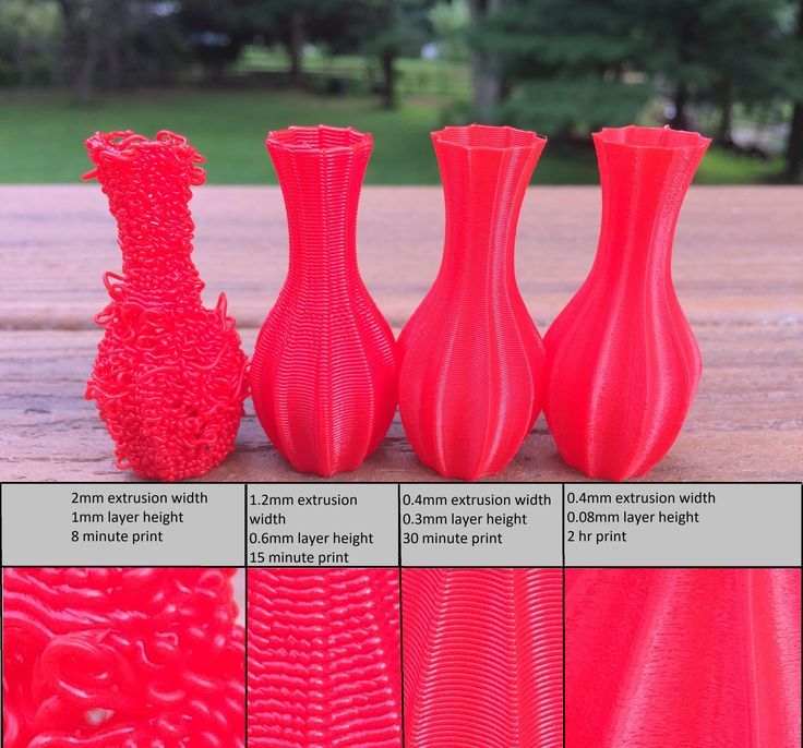
This image shows the effect of increasing angle on overhang quality for FDM printingWall thickness for 3D printing
The second thing to keep in mind when designing a part to be 3D printed is wall thickness. Every 3D printing process has its own level of precision. FDM, for instance, is the least accurate, while SLA has the tightest tolerances. In terms of part stability, every 3D printing process has a lower limit regarding wall thickness and feature size.
For example, imagine you are an engineer designing a new generation of hang gliders. You’ve chosen to 3D print a scaled-down version of the product to test its efficacy. 3D modeling programs allow you to model the sailcloth of the wing, for instance, but you then encounter problems when you would try to 3D print it. This is because the model’s wall thickness is less than the minimum required for successful printing.
It’s essential to make sure that your 3D designs have walls that meet the minimum required thickness for the printing process you choose. All 3D printers can successfully print components with wall thicknesses greater than 0.8 mm.
What is warping and how can you avoid it?
Something that is often easily overlooked while designing a 3D model is the fact that the materials used for 3D printing undertake physical change: they are melted, sintered or scanned with a laser and solidified. The heating and cooling of material can cause the parts to warp while printing.
Large, flat surfaces can be especially prone to warping. Warping can typically be avoided by using correct machine calibration and having adequate surface adhesion between your part and the print bed. A good practice is to avoid large flat surfaces and add rounded corners to your 3D models.
When you are creating a 3D model with intricate details, it is important to keep in mind the minimum feature size each 3D printing process can handle. The minimum level of detail is connected to the capabilities and mechanics of each 3D printing process and to the selected layer height .
The process and materials used will have an impact on the speed and cost of your print, so determining whether smaller details are critical to your model is an important design decision.
The most important thing to remember while designing for 3D printing is the fact that your digital design will become a physical object. In the digital design environment, there are no laws of physics to adhere to, such as gravity.
Anything can be "drawn" in 3D on a digital canvas, but not everything can be 3D printed. Knowing the key factors that go into designing 3D models will ensure that you produce digital designs that can be successfully printed.
Want to learn the key design elements for every 3D printing technology?
Design parts for FDM Design parts for SLA Design parts for SLS
Ready to transform your CAD file into a custom part? Upload your designs for a free, instant quote.
 Get an instant quote
Requirements for models for 3D printing
Probably every 3D modeler at least once thought about printing his model on a printer. Moreover, today it ceases to be something surprising.
Have you ever wondered what is needed for this? Are there any model requirements, or can any model be sent to the printer? Modeling for video games, movies, or any kind of visualization is different from modeling for print.
In this article, I do not describe in detail the ways and tools that can achieve the desired result - these are extensive topics and require separate consideration. Now let's talk about the goals: what you need to get at the output of the simulation, if you are planning to print the model.
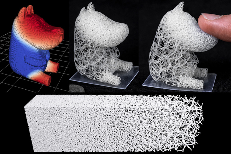
Here are examples of 3D printers and print results. Tall sticks and patterns are supports that the model rests on when printed. Later they are cut off, and, most likely, a little processing of the cut points will be needed to remove traces of the supports.
Print quality depends on many factors: the printer, the type of plastic, exactly how your model is placed on the print table, even the temperature in the room. In order for your model to print successfully, you must adhere to certain modeling and prepress rules.
The following basic requirements for the model can be distinguished: Integrity, or water resistance of the model (monolith) This means that there are no voids in the model, that all its details are combined into a single monolith. After modeling different elements of the model, it is necessary to combine them, roll them together. Undercuts As we see in the picture, all buttons are glued with additional elements to the main model. They do not hang in the air and do not touch the model partially, but completely, well attached to it. If small elements, such as buttons, fit well on the base, they will not fall off and will not be partially printed. The model should not have any gaps between the parts. Imagine that the model is placed in a liquid and must not leak into the gaps or "pockets" between the pieces. In the event that a plaster or rubber mold is to be removed from the model, these undercuts, or reversed angles, are especially important. They are easy to miss with the naked eye, so it is recommended to check the sectional model in special prepress programs. Here is an example when the backpack had an undercut: a very small thickness and air inside - as a result it crumbled. An important issue is the size of the file you are going to print. The model should be easy to work with, should not load the computer and printer to failure, so you need to reduce the file. Here is an example of the same file before and after facilitation. There are ways to reduce file size such as Decimation in Zbrush and Triangulation in Materialize Magics for example. Correct scale and detail of model The printer usually prints small objects such as miniatures or jewelry. Needless to say, how important it is to send a file for printing in the correct size? So, for example, Bismarck's head here is about 15 mm, and the visor on the helmet is not the same as in life, thin, but thickened. Otherwise, by reducing the model, we will get a visor so thin that it may not be printed or crumble - we are dealing with thin plastic. You can also call this principle “the purity of geometry”. The Demo Solder, which was just exported from Zbrush, shows that there are a lot of errors. The model has not yet been cured. The first three blocks, Model Integrity, Undercuts and Scale, refer to the modeling phase. You initially, when creating a model, keep these principles in mind, and by the end of the modeling, you have almost everything ready for printing. The many nuances to keep in mind when modeling for print may seem complicated, but don't get discouraged! Once you print your model, holding it in your hands, you will understand exactly how to make the next one. A little practice and you'll be fine! Bring your creative ideas to life! 01/16/2017 in 3D Modeling Instructions In this article, we will talk about the main and general parameters that a model must meet in order to obtain high-quality 3D printed products. Let's discuss common errors that occur in the process of creating three-dimensional models in terms of a high-quality polygonal mesh and how to quickly fix them. Requirements for 3D models and quality issues in terms of the accuracy of manufactured parts are described in another article: The actual size of the product after 3D printing. The structure of the additive manufacturing process for the production of products: In accordance with the presented algorithm, at the first stage of product creation, a 3D model is developed using modeling programs in accordance with the terms of reference and standards requirements. After that, it is necessary to export the data of the simulation result program file to a format accepted by the program of the additive manufacturing control machine (for example, “STL”). The modeling process can now be done not only in solid format, but also immediately in STL. During this procedure, you should select the desired scale of the part, the correct position in space, and accurately position the model on the work surface. The result of the whole process, strength, surface roughness of the part and material consumption depend on this . After the settings are made, the model is divided into layers of material, which are “fitted” into the body of the part in one working cycle of the additive machine. This process is called slicing. Slicing is done using the software supplied with the machine, or using special tools (Simplify, Skein-forge, Slic3r, KISSlicer, MakerWare, etc. In 95% of cases, file errors are not critical and can be easily corrected using specialized programs that can be easily found on the Internet. NETFABB - as a solution to most file errors. MESHMIXER is a powerful and convenient alternative. It should be understood that there are several 3D printing technologies. They differ not only in the materials used, but also in the accuracy of the equipment. Different equipment has its own resolution. Therefore, before sending the file for printing, it is necessary to make sure the quality of the model in terms of the specified thicknesses in the walls, rods, mesh ceilings. Detailed article about checking models for thickness. NETFABB (Download for PC or Download for Mac) is a program that allows you to solve almost any issue related to 3D printing. Let's go through the main functions of this software, which AutoDesk itself bought at one time. The program shows the outer part of the polygon in green, its inner normal in red. Ideally, the model should be all green. If you observe red spots, then these are polygons that are turned outward. If the entire model is highlighted in red, then the entire mesh is turned inside out. Even if the model is green, but there are errors in your file, the program will display a big exclamation mark in the lower right corner of the screen, and will also not be able to calculate the volume of your model. To treat the model, click on the red cross on the toolbar at the top of the screen. The program will put you into the treatment mode, and will indicate in yellow the breaks in the polygonal mesh, if any. This program has functions for removing or adding polygons, changing sizes or proportions. (I will leave these functions for independent study). I recommend that you study the entire toolbar in order to easily understand how, where and which polygons we can select and what we can change. To invert normals, select the polygons that look “in the wrong direction” and click on the “invert normals” button. Then click on the “Apply Repair” button. If your model was initially all green or inverting the normals didn't remove the exclamation mark, and the volume has not yet been calculated, you need to apply automatic treatment. To do this, go back to the treatment mode by clicking on the red plus. In the treatment mode, select "Automatic treatment", then select "Default Repair" and click "Extrude". The program has now done its best to repair the model automatically. Click "Apply Repair". Typically, these steps should have fixed your model. If after the performed operations an exclamation mark is on and there is still no volume, then you are among those 5% when the model has critical errors and errors are laid down at the modeling stage. Autodesk MeshMixer is a free program for working with 3D mesh models. As in the case of Netfabb, you need to drop the model in STL format into the MeshMixer program window. At first glance, the model looks good, but let's try to test it for suitability for 3D printing (mesh requirements). To do this, you need to analyze the model for errors. To do this, go to the “Analisis” section, then click on the “Inspector” button. On the screen, we see how the program has highlighted areas on the model with bright colors that do not meet the requirements, which means they have errors. In order to fix (cure) these errors, click on the “Auto Repair All” button. The program will try to remove errors automatically. Checking before 3D printing is a must. Even if outwardly the model seems suitable to you, it is still worth checking. In the picture below, you can see the errors that are inside the mesh, although everything looks good with the model. However, this treatment does not always help. For example, if the model has a huge number of errors that the program is not able to remove automatically, then you will have to correct the model yourself in the program where the model was originally created. In case of a large number of errors, the program will indicate their presence even after you have tried to do automatic treatment. The picture below is an example of a very large number of shortcomings and errors that the program is not able to remove by itself. This usually happens when the model is being prepared for rendering rather than 3D printing. The 3D model healing feature in Materialize Magic is located in the Fix tab. After that, select the “Correction Wizard” command. Next, you need to alternate the “Update” and “Autocorrect” buttons. Do this several times. Sometimes for a long time. Until the moment when the number of errors becomes minimal or disappears altogether. After the update, the result shown below can be considered successful. All checkboxes must be green. Complete the treatment by following the recommendations and save the corrected model! Very important point! Treatment in automatic mode occurs according to the principle of adding or removing polygons. Therefore, after automatic treatment, fully check the model for the correct form. Suddenly, the program removed something or added something superfluous. If we look at such a model in a section, we will see a single contour - the result of a Boolean union operation.
What can happen if we missed undercuts and didn't join all parts of the model together properly?
 It would be correct not to make the thickness of the backpack at all, and it would be good to deepen it into the main model, then combine it with a Boolean operation.
Print file size in megabytes
The model, at the same time, does not lose quality. After printing these two files, you will not see the difference. However, how important and desirable that your model is easy to use.
Heavy models are clumsy, take a long time to load and calculate before printing. Your model will print with the rest of the models on the table, and it should not load the computer to capacity. Therefore, keep an eye on the weight of the file and lighten before sending.
First of all, you need to double-check what units you are working in and not send in centimeters what should be printed in millimeters. The print specialist may notice the error and point out that the model is too small or too large, but he should not and cannot know what size the model you ordered.
As for the details on the model, I would not recommend making the model in an indefinite size or full size (human height), and then reduce it. If we are dealing with a miniature, then simply reducing the large model to the desired scale is not enough.
Details become too small when scaled down. They may not be printed or read expressively in the finished product. Here hypertrophy will be necessary: exaggeration of thicknesses and details.
Details on the helmet, such as the clasp or rivets, are also enlarged - this is the only way they will be visible to the naked eye in real life.
Conversely, if your model has very subtle patterns that go beyond the resolution of the printer, then you should not draw them. Details that are too small will smudge and merge, or not print at all.
Therefore, take an interest in the resolution of the printer, in what capacity the model is planned to be printed and miss the modeling of those details that are smaller than it.
Ability to pass preflight software check (STL Check) 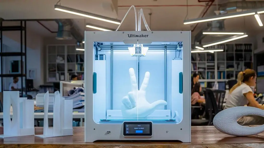
The term "Cure File" is used for a model that:
- consists of a single object (monolith)
- does not have holes
(unclosed triangles)
- does not have triangles that intersect or overlap each other, creating a double surface.
All these geometry defects are formed both during simulation (mesh overlaps, uncovered holes) and
during Boolean operations and file export. Before printing, the model must be checked in programs such as, for example, Materialize Magics, Netfabb or their analogues.
This model was not made for printing, but was created for visualization, therefore it requires gluing and removing triangle intersections.
An already cured dog model is an example of how the model should ideally be prepared for printing: one solid element (shell), without a ragged outline and intersecting triangles.
Chronologically, the steps that must be taken to comply with the principles of printing can be arranged as follows.
The last 2 principles: easy file and successful check - this is already prepress preparation, done after modeling. Requirements for 3D models for 3D printing and CNC processing
Contents:
Introduction.
The process of creating a product.
Designer / 3Dartist 3D Printing Service Discussed errors 1.  Creation of 3D model
 2. Export/convert 3D model to required format 3. Checking the model for suitability 4. Compliance/failure with minimum allowable thicknesses. 6. Preparation of control program for 3D printer (GCode) 5. Compliance / non-compliance with the requirements for the polygonal mesh of the 3D model. 7. 3D printing process. 9. Quality control. 8. Post-processing process.  Before the next stage, possible defects in the model are identified. A model intended for 3D printing must be hermetic, monolithic and not contain cavities and gaps in the walls, which is ensured using special programs. Next, the information from the STL file is converted into commands, following which the 3D printer produces a product, this is the so-called GCode.
  ). The G-code obtained in the previous step is transferred to the 3D printer via flash memory or via a USB cable. In the process of preparing and setting up the additive machine, calibration, preheating of the working bodies, selection of the model material and setting the parameters of the equipment operation modes that depend on it are performed. On professional level devices, this step can be combined with the slicing process procedures. After all the preparatory operations are completed, the printing process starts, that is, the layer-by-layer combination of materials. Its duration depends on the type of technology and the selected parameters for the accuracy and quality of the part.
 Requirements for models for 3D printing and CNC processing.
 STL .OBJ
 Even if you are sure that everything is in order with the model, it does not hurt to check it once again for correctness.
Fixing non-critical bugs with NetFabb.
Fixing non-critical bugs with MeshMixer.
 You can download the program from the link. The program does not have tools for creating 3D models, but a wide range of tools for modifying them and preparing them for 3D printing. The main difference between this software and NETFABB is that MESHMIXER officially supports the latest versions of macOS. For me, this is a decisive factor, because I always carry a MacBook with me, and a Windows computer is only in the office. In turn, NetFabb stopped supporting software for macOS.
 That is, there is a huge number of surfaces, but they are not connected into a single grid.
 Fixing non-critical errors with Materialize Magic
Learn more