How thin can you 3d print
Recommended Wall Thickness for 3D Printing
Time to read: 4 min
One of the most important considerations when designing parts for 3D printing in 2022 is the 3D printing wall thickness, sometimes referred to as the wall thickness. While 3D printing makes prototyping easier than ever—not only in terms of cost and speed, but also in regards to DFM (design for manufacturing), you can’t disregard DFM completely.
A design might be (barely) producible by 3D printing, but what happens when you move to the next iteration or the next stage in manufacturing? Ensuring that you have at least the minimum wall thickness for 3D printing is a good first step and a key 3D printing design rule. Finding the best thickness for 3d printing is an excellent skill to have for cost reduction purposes and structural integrity of your 3d printed parts.
Fictiv, your ultimate 3D printing manufacturing ecosystem partner, is here to help all our customers be successful in their 3D printing endeavors. To that end, here are our best 3D printing wall thickness design guidelines to ensure your print is printable and structurally sound, so you can design prototypes that can be produced in quantities of 1 and then ultimately 100, or 10,000+.
GET INSTANT QUOTE
3D Printing Wall Thickness Recommendations
There’s a limit to the minimum 3D print thickness a part feature can be designed for 3D printing.
Below is a table of our recommended minimum 3D print thickness for each material, as well as the absolute minimum thickness, for those of you who like to live dangerously.
NOTE: At Fictiv, we have had success printing parts as thin as our absolute minimum, but we can only guarantee a successful print at or above our recommended minimum. Under our recommended minimum, the thinner the part, the higher the chance something goes wrong in printing. Anything below our absolute minimum is unprintable in practice.
Why There are Limitations
There are a variety of limiting factors to consider, both during and after printing.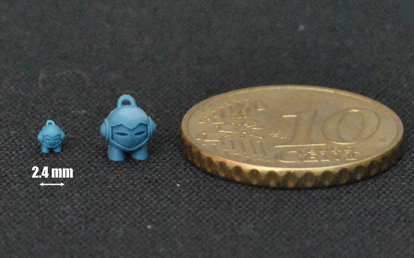
Limitations During 3D Printing
3D printers build parts in a single layer at a time. As a result, if a feature is too thin, there’s a risk of the resin deforming or detaching as it is extruded or cools, which means there isn’t sufficient material contact to connect it with the remaining body.
Additionally, you need a strong base to build a stable structure. If a part is being printed and the wall is too thin, that feature would likely bend before the resin can dry or cure. As a result, the thin wall would buckle, causing warping in the part.
Limitations Post Printing
Even if a thin-walled part prints successfully, the fragile part still has to survive cleaning and removal of support material. In addition, a thin-walled part may be damaged during removal
Cleaning methods include water jet, sanding, chemical support material removal, and picking away the residue. These cleaning techniques may cause thin walls to inadvertently break.
Additionally, in order to print such a thin wall, you often need extra support material or support walls. With the support material gone after cleaning, the component is even more fragile.
Minimum Wall Thickness vs Resolution
We often see some confusion around the difference between minimum wall thickness and resolution. Sometimes we’re asked, “If the resolution of a material is so high, why can’t the wall be that thin?”
Resolution comes into play in how detailed and precise a design can be, so long as there is enough thickness to provide structural support. Think of resolution as a factor of how well the details or surface finish of the part turns out to be.
Think of resolution as how accurate the part can be designed for printing, very similar to dimensional tolerance. Take a hollow sphere, for example. Minimum wall thickness determines how thin the shell can be so it’s printable and doesn’t collapse under its own weight.
Resolution determines how smooth the curvature is: low resolution will show visible “stepping” and roughness, while high resolution will hide these aspects.
Exceptions
Of course, there are always exceptions to the rule! Some parts can be printed with features below our recommended minimum wall thickness. Ribbing, cross supports, flat and supported components (as opposed to curved features) sometimes allow parts to be thinner.
While we aim to provide guidelines and recommendations around what we are 100% certain is printable, there are so many variables and design factors that make one thin part printable and the next one not. Because of this, we can only fully guarantee successful prints of designs above our recommended minimum wall thickness.
Main Takeaways
Though you might want to push the limits of your design, we don’t recommend going thinner than our suggested thicknesses. Even if your print is successful, that design choice will likely run you into complications around manufacturability down the road.
How will your thin walled 3D printed part be produced during the next phase, perhaps via RTV or Fictiv’s world class Injection Molding? Those thin walls will likely make your part impossible to manufacture at scale with 3D printing alone.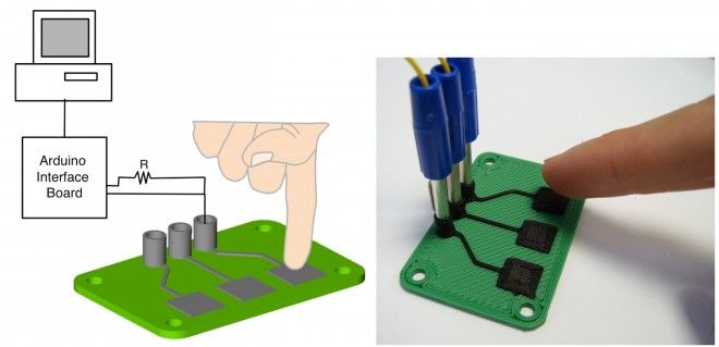
So, pay attention to the wall thickness of your parts, and if you choose to design a part thinner than our recommendations, be sure to carefully consider whether or not it will be manufacturable later on.
- For a start on determining a good wall thickness for 3D printing, visit our table “MATERIAL 3D PRINTING THICKNESS RECOMMENDATIONS” above.
- A good minimum wall thickness for 3D printing PLA is 1.5 mm.
- At Fictiv, the absolute minimum wall thickness a 3D printer can print is 0.6 mm. We cannot guarantee quality at this thickness though and it is not recommended.
Minimum Wall Thickness for 3D Printing
Choosing the right wall thickness is perhaps one of the most important decisions when designing parts for 3D printing. If the walls of your parts are too thick, your part will cost more to produce, take longer to print, and may even wind up cracking. If your walls are too thin, the part may not be functional, may warp during printing, or, once again, cost more to produce because you’ll have to go back and rework the design.
Understanding the minimum wall thickness for 3D printing will set you up for design success and lower your production costs.
Before we dive into the specifics of calculating minimum wall thickness, it’s helpful to clarify some important terminology.
Minimum wall thickness is the smallest possible thickness a structure can have while maintaining functionality. This minimum is impacted by several factors, including the type of 3D printing process you are using to print, constant physical forces (such as gravity), and how much pressure the structure you’re creating will be under during use.
Think of a graphite pencil. The thinner the point and the farther the shaft extends, the less pressure the graphite can withstand. The precise breaking point varies with each user as the precise pressure is unique to the person wielding the pencil. This is also the case for 3D printed structures.
An unsupported wall is one that connects with a second wall on only one side (or edge).![]() A supported wall is one that connects with two or more walls (on two or more sides).
A supported wall is one that connects with two or more walls (on two or more sides).
Wires are round as opposed to walls, which are flat surfaces. Due to their different physical shape, their minimum thickness is expressed as a minimum wire diameter. For a pillar or vertical wire, you’ll need to calculate the minimum vertical wire diameter (or thickness at the widest point in your circle).
When it comes to calculating the minimum and maximum thickness for intricate details, it’s important to understand the difference between embossing and engraving. Embossed details are those that protrude outward from a design, and engraved details are those that recede inward, or are concave.
In order to choose the perfect wall thickness for your design, you’ll need to consider three things: the purpose of your design, your aesthetic goals, and the physical 3D printing process.
Minimum wall thickness varies based on the type of 3D printer. You can use these design guidelines below as a starting point for choosing the right wall thickness for your model based on the 3D printing process you’re planning to use:
| Stereolithography (SLA) | Fused Deposition Modeling (FDM) | Selective Laser Sintering (SLS) | ||
|---|---|---|---|---|
| Supported Wall | Minimum Thickness | 0. 2 mm 2 mm | 1 mm | 0.6 mm vertical & 0.3 mm horizontal |
| Unsupported Wall | Minimum Thickness | 0.2 mm | 1 mm | 0.6 mm vertical & 0.3 mm horizontal |
| Vertical Wire Diameter | Minimum Diameter | 0.2 mm | 3 mm | 0.8 mm |
| Engraved Detail | Minimum Recession | 0.15 mm | 0.6 mm wide & 2 mm deep | 0.1 mm - 0.35 mm |
| Embossed Detail | Minimum Protrusion | 0.1 mm | 0.6 mm wide & 2 mm high | 0.1 mm - 0.4 mm |
In many cases, the manufacturer of the 3D printer or the 3D printing service provider offers a design guide with wall thickness recommendations based on testing performed on the specific printer model.
In general, SLA 3D printers can create the thinnest walls of all 3D printing technologies, but there are differences from machine to machine. For example, Formlabs’ own Form 3+ SLA printer offers more design freedom than its predecessor, the Form 2, because it uses a flexible resin tank to significantly reduce peel forces during printing.
If you are printing with an FDM 3D printer, recommended wall thickness can also change based on the size of the nozzle you are using. For example, if you are using a 0.4 mm nozzle, your minimum wall thickness should be divisible by 0.4, so instead of the 1 mm recommended minimum thickness in the table, you’ll likely get better results with 1.2 mm thick walls or by switching to a thinner nozzle.
Minimum wall thickness for SLS 3D printers is between the SLA and FDM, but offer some unique benefits, as selective laser sintering does not require support structures because unsintered powder surrounds the parts during printing. SLS printing can produce previously impossible complex geometries, such as interlocking or moving parts, parts with interior components or channels, and other highly complex designs.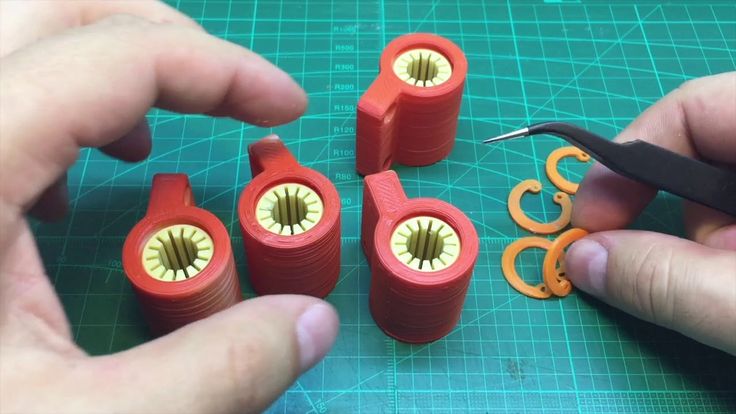
The purpose of your printed part should inform not only the proper wall thickness but also the 3D printing material you choose. If you’re designing a pliable part for printing, for example with Flexible 80A Resin, your walls will need to be thick enough to allow for compression of your piece but thin enough so as not to restrict movement.
The impact resistance and tensile strength of the 3D printing material you are using will impact the ideal wall thickness as well. For example, Rigid 10K Resin for Formlabs SLA 3D printers is reinforced with glass to offer very high stiffness, making it highly resistant to deformation over time and is great for printing thin walls.
If you’re printing manufacturing components, such as thermoforming molds or manufacturing aids that will need to withstand repetitive force or pressure, you’ll want to stick within solid parts or thicker walls. Very thin walls won’t be durable enough to withstand multiple cycles.
Color, finish, and detailing are important, particularly if you’re printing a looks-like prototype, a figurine, or an art installation. The good news is, if you consider recommended thickness early enough, you can design your piece to work within the limitations of 3D printing.
Let’s say you’re designing a figure with a button-up shirt, and those buttons are going to be embossed details. You can use some quick calculations to make the buttons thick enough to show clearly in your printed figure and make sure they are spaced out an appropriate distance.
There are a few common concerns every designer needs to be aware of when preparing a model for 3D printing. Understanding these limitations will help you avoid having to reprint your models.
Wall thickness issues are often the result of a disconnect between the modeling and printing processes. Models may appear to be structurally sound within your CAD design software but simply do not work in the real world. For example, architectural details, such as awnings, are likely to become impossibly thin if you scale a building down to a small tabletop model.
If your walls are too thin, you run the risk of your printed part warping or cracking either during or after printing. During printing, each layer of your printed design needs to have a certain amount of contact with the previously printed layer. If this isn’t the case, you may wind up with sagging, bowing, or completely disconnected parts.
After your design has printed, it needs to be able to stand up to cleaning and long term usage. Even if you are designing a figurine that is simply going to sit on a shelf, thin walls are more likely to creep and crack once they’re detached from the support structures.
In 3D printing processes that melt or sinter raw material, such as FDM or SLS, corners are particularly prone to curling. Depending on the shape, contour, and wall thickness of your design, certain areas will cool faster than others. This can result in areas, such as corners of a wall, curling as they go through the drastic temperature change.
Most 3D modeling software tools offer various features available to help you check and adjust the wall thickness of your design before printing.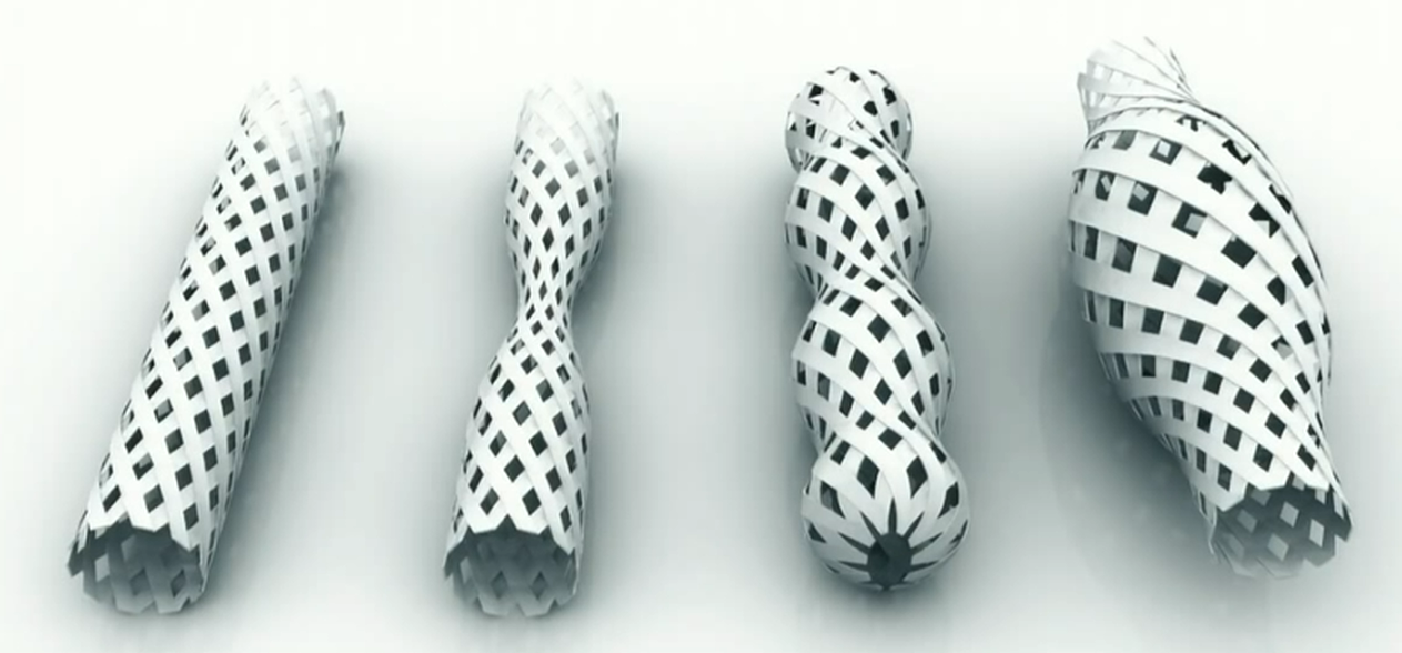 Here as examples with some popular CAD tools:
In MeshMixer, use Analysis → Thickness to verify if the wall thickness of the model is within acceptable limits for the given 3D printing technology. In case you need to add thickness to a mesh, you can use the Extrude command. Select the area that needs thickening using Brush mode, which allows selecting (and deselecting by holding Ctrl) individual triangles. It is possible to smooth the selection by choosing Modify → Smooth Boundary from the popup menu. Increasing the Smoothness and Iterations parameters will result in a more clean selection. Now, choose Edit → Extrude (D) with Normal as the Direction setting.
You can add thickness to a model using the Brush mode in MeshMixer.
Read our MeshMixer tutorial for 15 pro tips to learn how to optimize a triangle mesh, resculpt entire sections, stylize the model, or add useful features to it.
In Fusion 360, you can use the Thicken feature to adjust the thickness of individual walls.
In Rhino, you can use the Extrude Surface feature to create thicker walls or planes.
Subtleties of 3D printing. Part 2. Theory and practice.
I continue the series of articles started with the part devoted to polymers. This part will be devoted to the theory and practice of 3D printing, and I will try to reveal the questions that arise when in practice it turns out not quite what, it would seem, is theoretically known.
To begin with, a little elementary theory of FDM printing, which seems to be known to everyone and everyone :)
It would seem, what could be simpler? There is a rod on a reel that enters the magic hot end, where it melts and gradually, like toothpaste from a tube, is smeared in layers. During this process, our printout grows. Everything seems to be simple, but not quite.
The fact is that as soon as the plastic bar starts heating in the hot end channel, it begins to expand. A strange picture arises: let's say, 1 cubic centimeter of plastic enters the hot end of the print head, and a slightly larger amount of it comes out! And it would be fine if it remained so later - we would put up with this strange mathematics that violates the laws of conservation of energy. But, that's bad luck, as soon as the plastic leaves the print head through the nozzle and starts to cool, it begins to strive to return to its original volume.
At the end of the first part of the article 'Polymers', I already considered this issue and gave a general advice: do not heat the plastic beyond the temperature necessary to achieve good adhesion between layers, since the shrinkage of the heated plastic is the stronger, the higher the printing temperature. For each of the plastics used in 3D printing, this temperature, of course, has its own and is experimentally in the temperature range indicated by the manufacturer of the rod on the package.
Why doesn't the manufacturer specify a specific ideal temperature?
The fact is that we all use printing for a variety of, sometimes very bizarre purposes! Someone needs the highest detail when printing small objects, and someone prints final products of very decent sizes.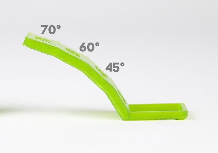 Someone needs only the appearance of the prototype, while someone else is interested in the mechanical strength of the resulting printout.
And it is very important to understand for yourself what you want to get, since getting a full set of these properties can be quite problematic. Not everyone prints for themselves and for their own purposes, many also print to order, and here you should be very good at both the theory and practice of printing, and even be a materials scientist to some extent in order to offer the customer the material, model and printing method that is the most he will be satisfied in the form of a finished result.
In general, the lower the printing temperature of a particular plastic, the higher the detail that can be obtained, but the less mechanical strength of the printout.
How can I increase print durability without increasing the print temperature?
In order to get an answer to this question, you can dig into the jungle of mathematics, again recall the forces of van der Waals . .. but you can simply give clear examples from the life around us.
Have you ever tried to separate 2 even panes of glass lying on top of each other? The larger their area and the smoother they are, the larger the surface of their contact and the more difficult it is to separate them.
The same relationship can be traced with 3D printing. The larger the contact surface of the subsequent printout layer with the previous one, the better the adhesion between them.
What influences the size of this area, apart from the area of the printed layer itself?
Nozzle size and printing temperature have the greatest influence on the area of contact between layers. The higher the temperature, the less viscous the plastic comes out of the hot end, so it 'wets' the surface of the previous layer better.
* What's interesting is that, theoretically, the rougher the surface of the previous print layer, the better it will adhere to the next layer, at the right print temperature!
The illustration shows 3 variants of layer sections. 1 - typical result of too low print temperature; 2 - ideal, when the fluidity of the plastic is sufficient to fill the irregularities of the previous layer; 3 - an imaginary super-ideal variant of the increased bonding area due to the uneven surface of the previous layer.
Visually, the difference between options 1 and 2 can be seen on the transparent plastic printout. The printout begins to shine throughout its entire thickness, as if it is all pierced with thin silvery threads. In essence, it is - the silvery threads are the air remaining between the layers.
Most of the air remains at the junction of the perimeters, due to the fact that the 'sausage' of plastic extruded from the nozzle in cross section is not a rectangle, but a rectangle with completely rounded edges. It is in the places of the side joints of these 'sausages' that the air lies, which reduces the strength of the printout.
You can reduce the number of joints by reducing the number of elements forming the joint!
Of course, the ideal option for a plastic product with properties that are homogeneous throughout its thickness is casting - one element per product. But we are talking about 3D printing.
Accordingly, in order to obtain the most durable printout, it is necessary to maximize the diameter of the nozzle used and the layer thickness, thus reducing the number of elements!
The layer thickness must not be increased excessively, as well as the nozzle diameter. But if everything is clear with the diameter - the smaller it is, the higher the possible detailing, then with the layer thickness, everything is not so transparent, since it does not affect the detailing so much due to the fact that it is smaller than the nozzle diameter. And the question is how much less?
What is the nozzle diameter and layer height in terms of slicer mathematics?
The slicer does not see what nozzle you have in the printer. And he will not even be able to check if you deceive him :) And here's why: for the printer control program, as well as for the slicer that prepares the code for the control program, the nozzle diameter and layer height are no more than 2 variables based on which it is calculated the amount of plastic that needs to be pushed through the hot end while it moves 1 cm away. That's it!
Accordingly, if you are sure that more plastic will certainly crawl through the nozzle installed on the printer, feel free to set the diameter of the nozzle larger than the physical one. Smaller sizes can also be displayed. But here, as elsewhere, there are limits. And if everything is clear with a programmatic increase in diameter, then a programmatic decrease in the diameter of the nozzle can give instability to the flow of plastic and its separation from the nozzle. This is especially noticeable in the filling. So if your fill mesh is constantly tearing - just set the nozzle diameter to a larger one.
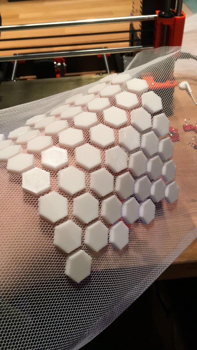
*The photo shows the results of printouts made with a 1.2mm nozzle. In the slicer parameters, nozzles 2, 1.5, 1.3, 1, 0.8, 0.5 mm are set in series.
It is not necessary to use the same diameter nozzle for all printing operations! Ask how? So you have never gone to the Advanced tab in the Slic3r settings.
It is quite possible to set the program diameter of the nozzle to 2mm for filling, and leave 1mm for perimeters and continuous filling.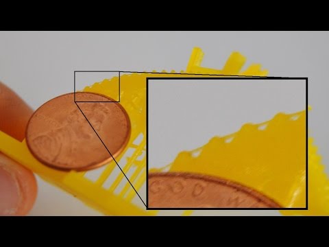 Or vice versa.
*The photo shows the results for these two options.
Correct ratio of nozzle diameter to layer thickness.
It should be clear to everyone that if the layer thickness is equal to the diameter of the nozzle, then the printout will be nothing more than a bundle of weakly glued bars equal in diameter to the nozzle! This option can just be seen in the illustration in the upper right corner.
* The illustration shows a plate of the most suitable ratios of nozzle diameter to bed height. In general, the smaller the layer height, the smaller the number of nozzles you need to print. The ratio of nozzle diameter to layer height is approximately 2-4 to 1.
But, it would seem, why is it bad to set the layer height to be much less than the nozzle diameter? Of course, the height of the layer can be reduced to a certain limit, but not infinitely, since errors begin to accumulate over time and artifacts form on the surface (outer perimeter) of the printout.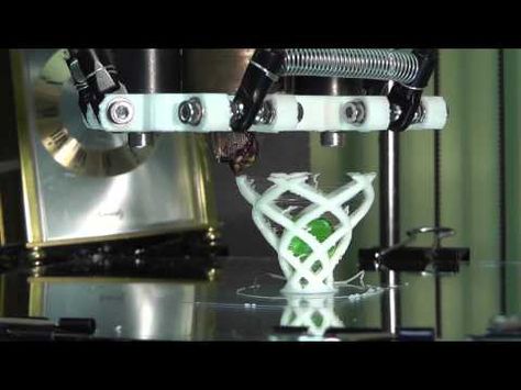 This is most likely because the plastic flow is forced to spread over the not perfectly flat surface of the previous layer, thus increasing the error from layer to layer or repeating it with a slight offset.
If the layer height is increased, then the errors are hidden and become less noticeable with each new layer.
* Photo prints made with 1.2mm nozzle (2mm nozzle size is set in slicer settings) with layer height from 0.4, 0.3, 0.2, 0.15, 0.1mm. It is easy to see that surface artifacts appeared on the printout with a layer of 0.1mm.
Based on the above arguments, it can be concluded that the correct ratio of nozzle diameter to layer height should be observed in order to obtain the best quality printouts.
What is typing speed in terms of mathematics and physics?
Simplifying the diagram as much as possible for clarity, we get a clear picture of the fact that: the speed of printing is primarily reflected in the volume of plastic that needs to be heated and forced through a nozzle of a certain diameter.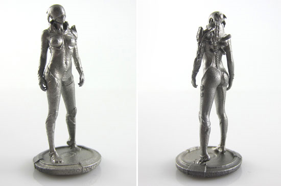
We will not consider such speed limiters as the design of the printer and its kinematics, as this is beyond the scope of the issues discussed in the article.
In fact, the most significant print speed limiters are 2 parameters:
- hotend power (it must melt the maximum amount of plastic per second)
- nozzle diameter (the maximum amount of melted plastic per second must pass through it)
We all probably still remember the problem from the school algebra course: calculate how much you need to increase pipe diameter so that water from the pool pours out 2 times faster;)
So it turns out that if we have a specific printer at home or at work, then we can increase its printing speed only by increasing the melt temperature (increasing the power supplied to the hotend) and increasing the nozzle diameter.
Moreover, in order to increase the print speed by 2 times, you need to increase the nozzle diameter by about 1.4 times :)
Cooling.
So, we have increased the print speed by 2 or even 3 times. OK! Great. But here's the bad luck, according to the law of conservation of energy, if we started to heat the plastic 2-3 times faster, then we need to cool it just as fast. Otherwise, completely unplanned failures caused by plastic sagging are possible, especially if you print with plastics with a low glass transition temperature (simply, they take a long time to harden). Such plastics include PLA and its mixtures, as well as the majority of impact and frost-resistant plastics - thermoplastic elastomers, including Filamentarno plastic! Prototyper of our production.
*The photo shows a typical result of insufficient air circulation on the printout.
Airflow is one of the thinnest and most difficult tools in 3D printing. And it is as useful as it is difficult to master.
Printing bridges, overhangs, small details, small models - all of this is almost impossible to speed up without the use of blowing the printout.
The blowing power should be considered as a parameter interconnected with the print speed - the higher it is, the more powerful the blowing should be.
Epilogue.
Briefly, all the abstracts of the article can be reduced to the following:
Do not increase the printing temperature beyond what is necessary to achieve sufficient adhesion between layers***
Experiment with all materials available on the market - this will help you understand the range of possibilities available to you
* **
Use nozzles of the right size for the purpose; be sure to have several from 0.2 to 1.2mm
***
0003
***
Match layer height to nozzle diameter
***
Match print temperature to both print size and nozzle diameter
***
Select blower power according to print speed
That's all for now!
The next article in this series will most likely be about print modeling.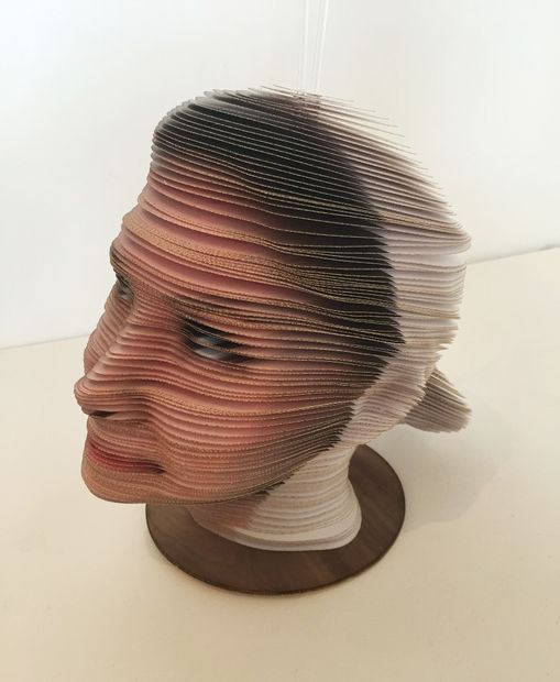
It is worth remembering that printing on an FDM printer with plastic is a process similar to casting. Accordingly, the requirements for the model should be the same as the requirements for the master model for plastic casting.
Best regards, Filamentarno team!
Manufacturer of unique materials for 3D printing.
www.filamentarno.ru
Recommended wall thickness for 3D printing
3DPrintStory 3D printing process Recommended wall thickness for 3D printing
One of the most important factors in designing models for 3D printing is wall thickness. While 3D printing makes prototyping easier than ever - not only in terms of cost and speed, but also in terms of DFM (Design for Manufacturing) - DFM cannot be completely ignored.
A model can be 3D printed, but what happens when you move on to the next iteration or next production step?
And this is where, basically, the wall thickness of your 3D model comes into play! In this article, we will consider recommendations for obtaining really high-quality 3D models that can be used in the future as full-fledged product prototypes.
3D model wall thickness recommendations
There is a limit to how thin a part can be for 3D printing.
Below is a table with the recommended minimum thickness for each material, as well as the absolute minimum thickness for those who like to walk on the edge of acceptable possibilities :) Successful 3D printing can only be guaranteed using the recommended thickness - the first line of the table.
Actually, the thinner the part walls, the more likely it is that something will go wrong during 3D printing. Anything below this absolute minimum is not practical for 3D printing.
Why are there restrictions on the wall thickness of the model during 3D printing?
There are many limiting factors to consider both during and after 3D printing.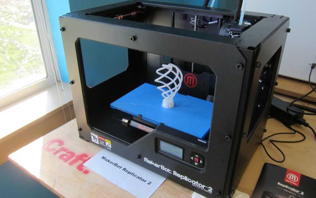
During 3D printing
3D printers print parts one layer at a time. As a result, if the element is too thin, there is a risk of deformation or delamination of the polymer, which means insufficient contact of the material to connect it to the rest of the body.
Also, just as you need a strong base to create a stable structure, if a part is printed and the wall is too thin, the part is likely to bend before the material can dry or cure. As a result, the thin wall will buckle, causing warping of the part.
After 3D printing is completed
Even if a thin-walled part prints successfully, the fragile part must still survive cleaning and removal of the base material.
Cleaning may include high pressure water jetting to remove residue, so many delicate components break at this stage. In addition, thin wall 3D printing often requires additional support material. Since the calipers are removed after cleaning, the part becomes even more fragile.
Minimum 3D model wall thickness depending on 3D print resolution
Many 3D printer users get confused between the minimum 3D model wall thickness and resolution. Often you will come across questions like: "If the resolution is so high, why can't the wall be so thin?"
Resolution refers to how detailed and accurate the finished 3D model will be if the wall is thick enough to provide structural support. Think of resolution as how accurate the manufactured part will be. This is a characteristic similar to dimensional tolerance. And the wall thickness of a 3D model is somewhat different. Take, for example, a hollow sphere. The minimum wall thickness determines how thin the shell can be so that it can be printed on and the model does not collapse under its own weight.
The resolution of a 3D print determines how smooth the curvature will be: low resolution will show visible "steps" and roughness, while high resolution will hide these aspects.
Exceptions
Of course, there are always exceptions to the rules! Some parts may be printed below our recommended minimum wall thickness. Ribs, cross supports, planar and supported components (as opposed to curved elements) can sometimes be printed with thinner wall thicknesses.