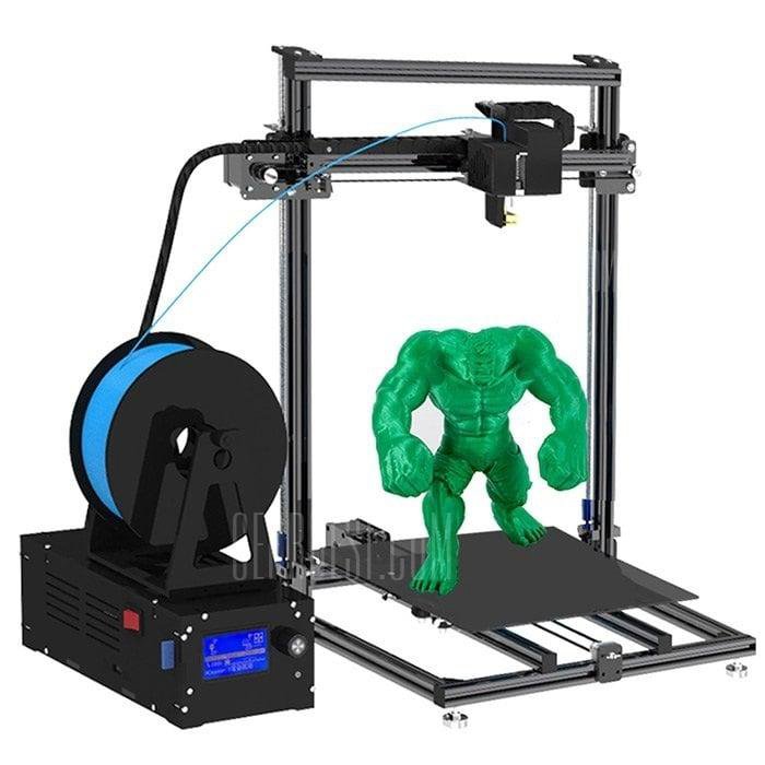
3D printing cylinder
3D Printing Cylinders How To Do It? – Printing It 3D
Cylinders look deceptively easy to 3D print, but figuring out how to keep them hollow and durable during the printing process can be challenging. Still, if you have difficulty printing up a cylinder, you likely need to know the peculiarities of printing these shapes. When you know the proper steps, whipping up a cylinder is simple.
Here’s how to 3D print cylinders:
- Locate the proper orientation.
- Choose the printing method.
- Address the possible problems in printing 3D cylinders.
Printing a 3D cylinder is quite different from printing solid objects, but creating hollow objects on the 3D printer will save money and time. So, let’s go through the steps for 3D printing a cylinder. I’ll also tell you more about potential problems and how you can preemptively correct them for a perfect print.
1. Locate the Proper Orientation
There are two main ways to print a cylinder, horizontally or vertically. The choice you make for orientation is the most important as you want to maximize strength and guarantee the best surface quality.
To optimize the position of your 3D print on the bed:
- Open the model on your computer and slicer to orient it so that the surface will stick to the bed. You want to eliminate any possibility of wobbling or movement.
- Place the largest flat surface on the print bed. When there are no visible large flat surfaces, use a raft and supports to lay down the first layer.
- Optimizing the cylinder’s first layer will help minimize the layer lines. Minimizing these micro-stepping lines will reduce post-production manual cleanup.
Since a cylinder has two flat surfaces with one on each end, placing one of these circular ends directly on the print bed will usually give you the best chances of success. However, since you’ll have more layers to print when working in this direction, your cylinder will not be very strong.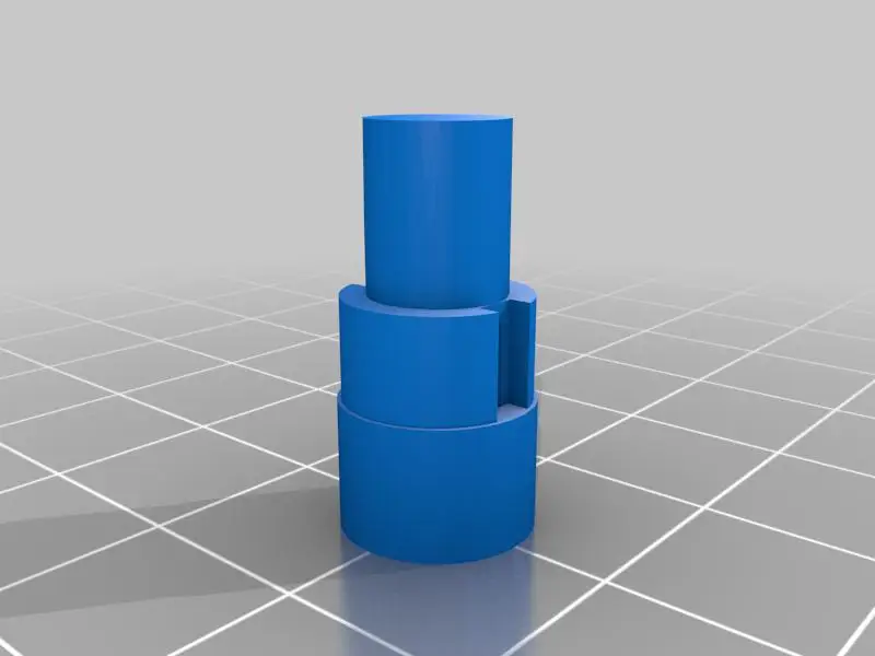
On the other hand, if you add a raft and supports to print your cylinder horizontally, you will ultimately get a much more durable 3D print.
So, if you want a durable print, you may need to spend more time on design and add some support. If your cylinder will not undergo stress, you can stick with the much simpler method of placing one of the flat ends on the bed.
2. Choose the Printing Method
There are three main printing methods to create a 3D hollow cylinder. However, since 3D models are usually solid prints, you must make several adjustments to build a hollow model.
Let’s look at how you can achieve a hollow shape with your slicer, vase mode, and meshmixer.
The Slicer Method
Most 3D printing enthusiasts say the slicer method is relatively easy. Using Cura software, complete the following steps.
- Adjust the density level of the infill.
- Load the model into the Cura software.
- Choose either the preset infill adjustments or custom settings to control infill density.
- Enter the infill setting.
- Slice the model.
- Save the model for printing.
The Vase Mode
Cura and a few other CAD programs also have a Vase Mode that gives you single-wall shell thickness on 3D cylinders. Vase mode prints the outer wall contours using a continuous, single line. This Youtube video demonstrates Vase Mode.
Here are the steps for using Vase Mode to print a 3D cylinder:
- Load the 3D model into Cura software.
- Select custom settings.
- Choose “Special Modes,” and the menu will show up.
- Choose both “Smooth Spiralized Contour” and “Spiralize Outer Contour.”
- Slice the 3D model.
- Save the model and print.
The Meshmixer
One of the main benefits of using Meshmixer is that it lets you choose the wall thickness and hollow out a model. You can improve the strength of the wall by controlling the thickness.
To use Meshmixer for creating hollow cylinders, follow these steps:
- Import the model into Meshmixer.
- Choose Edit from the menu.
- Choose the “hollow” preference.
- Select the thickness of the walls with the offset slider.
- Specify (if using resin) the number of holes.
- Click “Update Hollow.”
- Click “Generate Holes.”
- Check the parameters.
- Save the model into your desired format.
3. Address the Possible Problems in Printing 3D Cylinders
You can encounter problems when printing 3D cylinders, some of which are tricky to solve.
Here are some of the most effective methods for printing solid and seamless cylinders:
- Orient the cylinder for the most print bed contact possible.
 Finding a flat surface of the model is the best start for the cylinder. Ensure the settings for the model are correct, as this affects adhesion, too.
 - Add rafts and supports when necessary. To remedy the problem of no flat surfaces, you can cut the model or print with a raft and supports.
- Change the orientation to reduce layer lines. Optimizing the orientation will minimize the appearance of layer lines and ensure that you have the best layer adhesion possible.
- Adjust your fan to compensate for thin or warped first layers. If your cylinder has a thin, saggy, or warped first layer, adjust your fan speed (or move your supports and orientation for resin 3D prints).
- Avoid supports on a large model by printing in sections. Printing your model in several parts, then putting them together later can produce a more professional model without any marring resulting from removing supports.
- Try again until you find a setting that works.
 Evaluate the X, Y, and Z axes to choose the best printing orientation to minimize weak points and prevent fracturing.
If you want to reduce the appearance of seams and layer lines in Cura, check out this tutorial on Youtube:
Final Thoughts
When you want to create a 3D printed cylinder, here are some ways to ensure that your print turns out right the first time, saving you time and money.
Locate the best orientation so you can start the printing on a flat side of the model for the best adhesion. Choose the printing method to reduce the need for a raft and supports. Finally, anticipate the problems to produce the most flawless cylinder that you can print.
Slicer settings for a horizontal cylinder - 3D Design
3D Printing SpaceMr.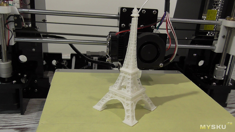 Croquet
#1
I’m printing a cylinder 16mm diameter and about 3 inches long. For strength, it needs to be printed horizontally. I’ve been working with PLA+ but anything stronger is also open to consider. The problem with the print is that it has 2 flat sections on the underside (around 4:30 & 7:30) a bit before & after where the supports end
My support settings in CURA 4.9 include
Layer height 0.2 (tried 0.15 with same results)
Infill 100% using lines (100% needed for strength)
Wall thickness 3 lines
Print speed 80 mm/s
Temperature 200 C
Part cooling 100% always on
Support angles tested 30, 45 & 50
Support Z Distance 0.2 (equal to layer height)
Am I missing something obvious or are circular parts just not able to be printed reasonably close to their shape on the underside?
kitedemon
#2
I have printed a number of cylinders laying flat. I have not seen what you are describing. Is this the interface layer still attached? That is the layer between supports and part. First guess.
Try a different slicer. I now use exclusively Prusa the paint on seams and supports is too good to pass up.
Things to change Prusa has supports that are tough to remove, under print settings / support material/ contact z distance I like 0.3 sometimes even 0,4 the 0.1 default is too close for course layer heights I typically use.
I also often use 3-4 interface layers, it makes it easier to pull off. That setting is 5 spots below contact dis.
Albergman
#3
I’m a newbie to 3D printing so forgive me if I’m missing the obvious. My current project needs 3 cylinders which will be glued together and I printed them standing vertically. I’ve had no problems with them and I should mention there’s no strength requirements. They’re about 2" diameter and 3" long each.
Help me understand why you have to do them sideways “for strength” as I’m just learning.
LEGOManiac
#4
In a theoretically perfect world, you don’t have to print them horizontally, but here’s why the world isn’t perfect:
As you lay each layer of filament, it should theoretically come out hot enough to melt part of the layer below and beside it so that the previous and current layers weld into one uniform piece. There should also, theoretically be exactly enough filament extruded to fill in the gaps - remember the filament comes out as a cylinder.
In there real world, there are almost always some gaps left between layers. It’s a very fine line between filling in the gaps 100% and over extruding, which gets messy. Obviously, air gaps create weakness.
Similarly, if the newly laid filament isn’t hot enough to melt the adjacent filament, it will stick, but not weld together. It’s another major point of weakness. Easy! you say, I’ll just crank the heat up! Well, that leads to stringing, sagging of filament along the edges or overhangs, and imprecise fit for mechanical parts. Also, there’s the phenomenon of “heat creep” where the filament and fans can’t extract the heat fast enough such that the hot spot begins to move up the hot end and into the Bowden tube which will jam the filament. In very extreme cases, you can actually burn the filament which changes it’s physical properties and causes jams in the nozzle, so again, finding the perfect balance is tough.
The end result is that you will pretty much never get the mechanically solid properties you could get from extruded pipe, even though both the extruded pipe and the printed pipe may be made from the same type of plastic (ABS for example).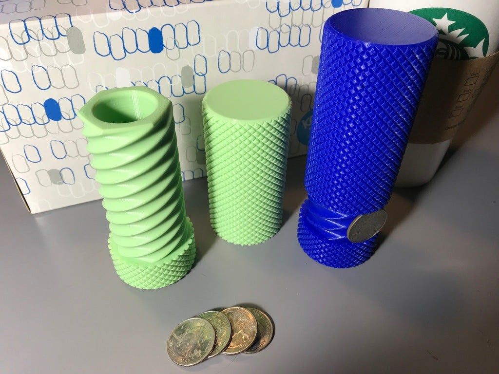
Since the air gaps and inconsistant melting defects are introduced as the layers are laid down, the weak zones follow the layer lines.
This in turn means that a 3D printed part will inherently be stronger in the direction across the layers, since each layer is laid down as a single extruded piece of plastic, whereas the strength along the layers alternates between strong (within the layer) and weak (between the layers). They will almost always fail along the seam between layers.
If you print the pipe vertically, such that the layers go across the pipe, you will also have corresponding weaknesses going across the pipe with each layer. That means many, many, many points of weakness whereas if you print the pipe horizontally, you still get weakness between the layers, but the layers themselves run the entire length of the pipe.
Keep in mind that for most pipes, they experience bending across their widths more than they do along their lengths. (there’s probably a more technically accurate way to express that)
It’s similar, I suppose, to the concept of putting rebar in concrete. You could put a bunch of short rebar pieces oriented vertically, but the concrete will still be weak. The rebar has to perpendicular to the axis along which the concrete is likely to snap for it to do any good.
A continuous layer line is the plastic equivalent of rebar. Because it’s extruded as one continuous piece its bonds stronger within itself than the bonds are with adjacent, hardened, filament.
For funzies, you can just try printing a narrow tube in both orientations and try it for yourself.
Albergman
#5
Once again a really detailed , clear explanation … thanks for that. If I understand this correctly I’m thinking now that maybe I was very lucky not to have any layer separations. I remember that I re-printed all 3 after I discovered the “super-fine” settings in CURA and I wanted the finest surface available. They took a much longer time to print but are wonderfully smooth and needed only a fine coat of my fairing compound.
Sorry to hijack your query Mr Croquet.
1 Like
kitedemon
#6
Prints are almost always weaker at the layer lines, often a point of failure. It is why so many change the orientation of prints to difficult positions so the layer lines are not aligned with the direction of force.
Stephen does a lot of this type of strength test. He usually prints samples flat and standing. It is clear very quickly how orientation changes strength.
Mr.Croquet
#7
Not to worry about hijacking the thread. All this is good learning. I was lucky enough to be told to lay down this part for a stronger piece. I’ve attached an sketch of the nature of the defect in the print. This is an end view of the piece. The flats are symmetrical and on both sides of the support material. I’ve gone to as much as 50 degrees on support with no change. If anything, I thought I’d encounter sagging layers not the opposite.
Any thoughts on how to correct it?
1 Like
LEGOManiac
#8
I’ve always had good luck with tree supports, rather than a raft.
Mr.Croquet
#9
With the cylinder being only 16mm diameter and about 120mm long, is a tree support suitable? I thought tree supports were for taller & more complex prints. If you think it is better, I’m game to try. Here’s a screen capture of the part sitting in Prusa Slicer
LEGOManiac
#10
I’m not aware of there being any real “limit” to tree supports. I’d say give it a try.
kitedemon
#11
You are using a raft. Not just supports and skirt?
Is the part on the bed?
I print with the part slightly off the bed with raft and supports. I rarely see a flat. In prusa slicer I increase the distance of the support interface to 0.3 it is easier to remove. I sometimes increase the interface layers. Too.
Too.
Tree supports might help . I have never tried them with something so large.
Mr.Croquet
#12
The flats are very stubborn. After several other attempts at changes (tree support, angles, thinner layers) they just won’t go away. Is it appropriate in this forum to ask if someone with more experience is up to finding the correct setting that will round out my cylinder? If so, contact me and we can discuss it further. ([email protected])
kitedemon
#13
@Mr.Croquet I just printed a 20mm x 25mm tube. I used a raft and auto generated support material on the build plate only. It is round. Really ugly, it took 15 mins at 0.28mm layer height, very fast.
On the printer bed with raft.
Separated from raft. round no flat spot. UGLY!
Settings from Prusaslicer it was printed with. You can likely transfer these settings to your slicer of choice.
Mr.Croquet
#14
That looks impressive, compared to my results. I’ll try your settings and let you know how it works. Although I’m relatively new to 3D printing, I started with the latest version of Cura but recently downloaded the latest Prusa Slicer.
Mr.Croquet
#15
A few other settings that I think may be crucial. I have used layer heights of 0.16mm & 0.20mm and speed of 80mm/sec What is your layer height and print speed on this?
kitedemon
#16
Ok so the print is crude I wanted to be certain of what I was telling you was accurate. It is 0.28 layer height as course as I can get away with for anything. It was at 100 mm/s this is really too fast for this printer I was using it causes artifacts, but useful for quick drafts.
The setting that is important for your roundness is the raft settings. You need enough layers to fully support the starting point. 8 is this print. It was fully supported on the build plate. Typically a tube will self support. This is not always the case, ambient air temps and drafts may change that.
Your layer heights you can print well at will vary with your printer. My other printers don’t print well at 0.28 I don.t even bother. Others print faster speeds as they are more ridged. They are individual that way also two of the same mayn’t like the same settings.
SETTINGS ARE A STARTING POINT! You may need to tweek them.
I would strongly suggest when you have time and are not trying to print something specific, find a model that is not super difficult but isn’t really easy. and use that as a model to tune settings. Make a print change ONE thing (I make big changes at first) and see what it does. Many use a bench for this but I hate the waste. I printed tarp clips, something that if it was ugly it didn’t matter and you need a lot of anyway.
kitedemon
#17
@Mr.Croquet I just wanted to see if you had success with a bunch of raft layers?
I recently printed a standing cylinder and it was printed 120mm tall 8 parameters and 20 mm diameter with a 11mm hole.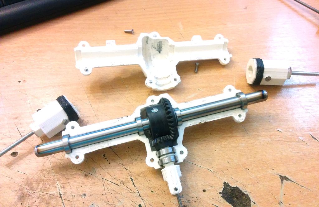 It is very tough, depending on how thick your walls are and what application it might be tough enough standing.
Mr.Croquet
#18
Hi kitedemon,
Thanks for all of your helpful suggestions. In the end, I started testing by using a cylinder of the same diameter (5/8") and 1-1/2" long, lying horizontal. I also discovered that Prusa Slicer’s default settings just about cleared up the issue. A few tweaks to those default settings made were:
- ‘With sheath around the support’ unchecked allowed for easier removal from support material
- ‘Overhang threshold’ set to 40 degrees
- ‘Layer height’ is 0.20mm
- ‘Raft layers’ set to 5
Interestingly, when printing 3 parts at the same time, separated by about 3/4", one end of each was perfectly round while the opposite end, the cylinder distorted into an oval cross-section. My next trial for printing multiples will be to separate them far enough on the bed to print sequentially. Time-wise, it is very helpful to be able to set it to print an hour before leaving work for the day and letting it continue for the 5 - 6 hours required for 3 pieces.
For those interested in remotely controlling their printer for free:
I took an old smart phone and mounted it on the printer frame with a $5 clamp mount with goose neck that I found at the dollar store. This phone and my current cell phone had a free app called ‘Alfred’ installed. I can remotely monitor the printing and if it’s dark, the flashlight option can be turned on. Very cool and total cost under $5. If anything goes wrong with the print, I can log into my desktop, running the printer thru Ponterface and stop the print.
1 Like
kitedemon
#19
That is curious. try turning them 90º on the bed. You could find on side it out. Some of the creality printers seem to have something out of square.
Mr.Croquet
#20
I have yet to find a suitable solution in the settings. I think I’m getting closer, having just viewed Youtube’s The 3D Print General’s video on ‘How to avoid needing support material’. Regardless of the support angle, the flats on the bottom of the cylinder show up where ever there is support (this could be a hint to the problem).
Using his suggestion, I slowed the perimeter speed right down to 15mm/s. That has had the most promising results yet. The only problem now is printing time has gone from 2 hrs to 5 hrs.
next page →
10 models for 3D printer calibration. Set up your printer
Before you start printing on a 3D printer, you need to test it. For this, special models are most often used to diagnose and calibrate the device. Next, we will list the top 10 models for calibration, in our opinion.
3D Benchy
Among all 3D printing tests, the flagship is 3D Benchy. This model is a boat that can test everything from protrusions to extrusion. If you want to test your 3D printer, then the benches will help you determine the optimal settings for the ideal result. On Thingiverse, more than three thousand users posted photos with their samples, and the boat itself was printed by more than a hundred machines and no fewer materials.
Model reference
All-In-One
A very interesting model, which is called “all-in-one”. Everything is presented in the model: canopy, bridge, string, temperature and belt tension test, extrusion. This is an ideal model for testing the device at several levels at once. A manual is included with the model to help you troubleshoot any issues you find. On Thingiverse, more than 75 users have posted test results on different 3D printers and different materials.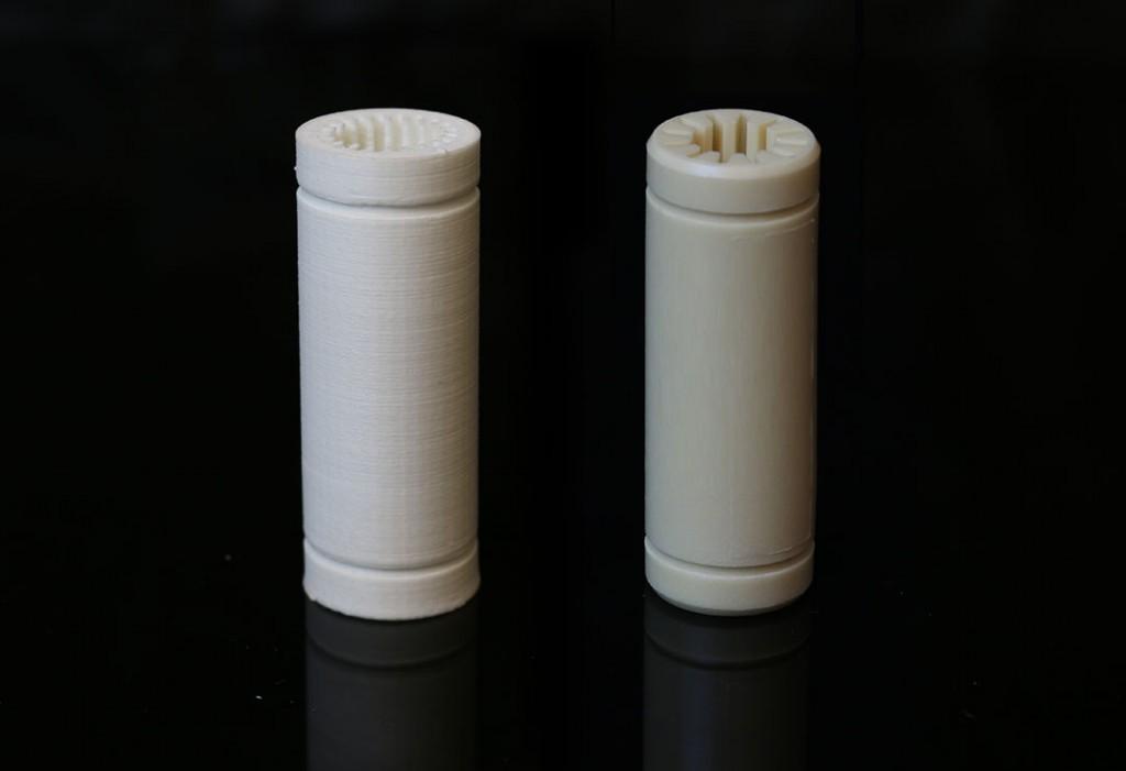
Model Reference
XYZ Calibration Cube
Very simple and fast model for testing. This is a cube with a side of 20mm. It helps to gain dimension by adjusting the steps in millimeters. Also, the model allows you to test extrusion, vibration, temperature. This cube was printed simply by countless 3D printers and a variety of materials.
Model Link
Cali Cat
Nice little calibration cat or just Cali Cat is a simple model that allows you to test the accuracy of the device, as well as detailing, lugs, bridges, vibration and extrusion. And all this in just one hour. More than 2.5 hundred users have submitted their test results on the service.
Model Reference
Phil A. Ment
The MatterHackers Mascot is a Phil A. Ment test model. It was originally intended for manufacturers. The description mentions the fact that Phil has several functions. And they were originally designed specifically for 3D printers. The model has small inserts, relief details, cylinders of vertical and horizontal orientation, ledges. In addition, the model contains chamfers, bridges and fillets. And this miracle is performed by a domed helmet. The record size on the service is 5,1397mm. A total of 84 models were published.
Model Link
Calibration Temperature Tower
You can use this model to adjust the heat of your 3D printer. You can also test for different materials at what temperature the print comes out better.
NEW model Autodesk
This is a new model, or rather not even a model, but a whole procedure that will allow 3D printer manufacturers to show all the capabilities of devices to Kickstarter supporters. And of course, calibrate. The test was developed by Andreas Bastian and is a consolidated STL file that is able to test the system for the following indicators:
- authorization;
- alignment;
- accuracy;
- bridge, etc.
The model has it all. For example, if the 3D printer is set up well, then the horizontal function will be performed with a minimum of problems.
Model Link
PolyPearl Tower
If you want to test curves, cuts, bridges, cuts, then this model can be a great solution. In the description for this test model, the name "torture tower with a twist" appears. It is worth trying to use it for calibration.
Model Link
Rapid Screening
This model is a very quick test to check temperature, cooling, and retract function. Among the advantages of the model is its cost-effectiveness. The model will weigh only 0.23g. With its help, you can immediately remove the "strings".
Model Reference
Parametric Calibration Object
A particular difficulty in calibrating a 3D printer is lowering the stage level. With this model, you can draw the right conclusions to improve the first layer of printing, and as a result, get better prints.
Model reference
8 test print models
3D printer test models are required for:
- When you bought a new printer and need to test it on your favorite media
- When you have purchased new media and need to check the print specifications
- When you have been using a material for a long time, but do not know its tensile strengths
We will talk about the 8 models most used for testing in 3D printing.
1. 3D Benchy
3D Benchy is one of the most popular 3D printer test models. The boat figurine perfectly demonstrates the capabilities of FDM printers in any price category. Such a model will help you determine exactly the settings you need to set in order to get the perfect 3D print.
Printing 3D Benchy - will allow you to see how the printer copes with the "rendering" of curved surfaces, inclined planes, arcs, holes. The model is available in several versions, including multi-color. It takes approximately one hour to print a standard size 3D Benchy.
Download model on Thingiverse
2. All-in-one 3D printer test
A comprehensive test model for a 3D printer will allow you to check the quality of printed overhangs, bridges, extrusion stability, the possibility of “snot” and the dependence of the result on temperature. An important advantage of this model is the instructions for it, which indicate potential solutions to various problems.
Quite a complex model in terms of setting all the parameters, but it's worth it, try it.
Download Thingiverse model
3. XYZ 20mm Calibration Cube
The main purpose of the XYZ 20 mm calibration cube is to establish the dependence of the movement of the extruder on the step of the motor. A test model for a 3D printer helps to make sure that 20 mm in the drawing corresponds to 20 mm of the printed product. At the same time, the calibration cube helps to establish the dependence of the degree of extrusion and print quality on the temperature of the extruder.
Download Thingiverse Model
4. Matter Hackers' Mascot Phil A. Ment
This is a small astronaut figurine that has elements designed to test 3D printing.
These are small inserts, small relief details, overhangs, vertical and horizontal cylinders, fillets, chamfers, lintels and a perfectly domed helmet.
A feature of the model is the ability to obtain accurate data for different dimensions of the printed product.
Download model on Thingiverse
5. Smart compact temperature calibration tower
The calibration scale demonstrates the capabilities of the 3D printer when printing at different temperatures with one filament. The test model clearly shows the quality of overhangs, lintels, tensions, and the product can also be used to judge the ability of a 3D printer to print curved surfaces with a certain plastic.
A simple and intuitive tool allows you to find out the possibilities of materials that have not previously been used in work or printed with only one temperature.
It is important to consider that the print temperature setting for each signed element (floor) must be set in the slicer or manually in Gcode.
Download model on Thingiverse
6. Open-Source Printer Evaluation
This is a universal print model from Kickstarter and Autodesk. It was created taking into account the experience of using other models for testing. It contains bridges, overhangs, fine detailing and elements for assessing the spatial accuracy of 3D printing.
Download model on Github
7. Economical Stringing Test
When printing complex-shaped objects, without knowing the capabilities of the filament and the printer, the user may encounter stringing (from string - string), and in Russian simply “snot” - when plastic reaches for the extruder, forming thin plastic fibers in the air. Such “snot” appears when the extruder is idle. To avoid this, the retract function is used - the retraction of the filament during idle movement. Correct setting of the retract level requires consideration of extruder speed, extruder temperature and filament properties.
This test model is used to quickly check the correct setting of the 3D printer. If the strings between the vertical pyramids do not form, then the settings are correct. If horizontal plastic filaments appear, then some of the 3D printing parameters should be changed.