Probe 3d printer
Auto Bed Leveling (ABL) Sensor Comparison – 3DMaker Engineering
One of the best upgrades you can add to a 3D printer to improve both performance and ease of use is an auto bed leveling sensor. Although they technically do not level the bed, they create a topological map of your bed and adjust the Z position of the nozzle to follow imperfections of your build surface for a more consistent first layer.
The first upgrade we do to all of our printers is solid mount the bed (remove the bed springs) and add an auto bed leveling sensor. This allows us to level the bed once and never have to worry about it again. When you have a print farm, the last thing you want to have to worry about is adjusting bed leveling knobs on a large number of printers.
Disclaimer: We currently sell a physical, hall effect type probe. We want to be upfront that we have not skewed our opinions based on this. The fact is, we tested each type of sensor extensively in our print farm and came to the conclusion that for our needs this was the most well-rounded option. Because of this, we decided to partner with a sensor manufacture to develop the 3DM Touch. We could have just as easily went with a capacitive or inductive style sensor which typically is much cheaper to manufacture.
If you Google “3D Printer Bed Leveling Sensors” you will find an endless number of manufacturers selling sensors of all shapes and sizes. To help simplify things we will break it down by sensor type instead of sensor brand. If you can understand the pros and cons of each of the technologies available it will help you determine the best one for your application.
Capacitive Sensor (ex. EZABL):
A non-contact sensor that can sense both metallic and non-metallic surfaces. This sensor works by monitoring the capacitance (how much energy the onboard capacitor can hold) which changes when an object is placed near its sensing face. It can detect any surface that has a die electric constant greater than air which should cover every build surface you will use (including glass). Another advantage of this sensor type is that it can probe extremely fast, saving you time during each print. Below is a basic diagram of how the sensor works.
One drawback is that while it can sense almost any surface, the distance at which it reads it will change depending on build surface type, temperature, and humidity. This is no problem if you only have one build surface and do not use an enclosure. If you plan to switch between different surfaces (ex. garolite, glass, PEI, polypropylene, etc.) like us, you will find yourself having to continually tweak your z-offset. Additionally, if you print in an enclosure where ambient temperatures vary, you will again need to adjust your z-offset.
Inductive Sensor (ex. P.I.N.D.A.):
This is another non-contact sensor, however, this type can only detect metallic surfaces. This means when the probe is analyzing a PEI spring sheet, it is actually mapping the spring steel and not the PEI surface you are printing on. This is usually not an issue, however, as the two surfaces should be relatively parallel with each other. If you are someone who likes to print on glass, garolite, or polypropylene—you may want to look for another option as these materials will not be detected. Although these sensors look very similar to a capacitive sensor, they work based on a completely different principle. They use the electrical principal called inductance. In a nutshell, an inductor coil in the sensor creates a magnetic field that changes when a metallic object is within its sensing distance. Non-metallic surfaces do not affect the magnetic field which is why the surface must be metallic.
Similar to the capacitive sensors, their readings are affected by temperature and humidity changes, so be prepared to make adjustments if you expect to see large temperature shifts. Some printer manufacturers, like Prusa, have done their best to use onboard sensors to automatically adjust for ambient temperature changes but in our experience it’s hit-and-miss. We have MK3S printers where we calibrated the z-offset at room temperature, put them in a heated enclosure, and found that the z-offset was then completely incorrect. If you are not printing in an enclosure, the temperature compensation seems to work fairly well for minor changes in room temperature, which is what we think it was really intended to do.
Physical-Hall Effect Sensor (ex. 3DM Touch+):
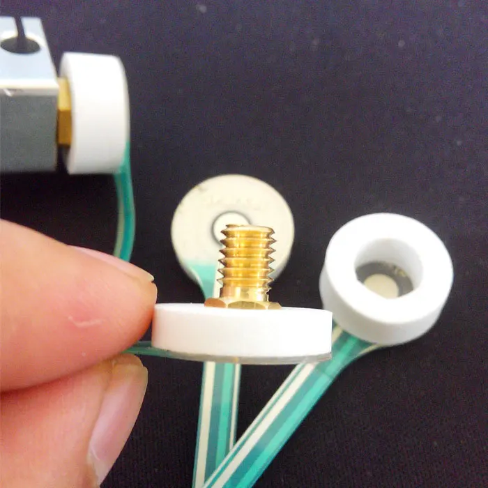
This is the only sensor on the list that actually makes contact with the bed as a means of detection. Because of this, it is unaffected by temperature and humidity changes like the other two contenders. It functions by using a plastic plunger (pin) and a hall effect sensor to detect your build plate. As soon as the plastic pin makes contact with the bed, it is retracted and registered by the hall effect sensor. Also, there is a built-in solenoid that allows you to extend and retract the probe via g-code which gives you plenty of clearance while printing. Below is a diagram of how a basic hall effect sensor works. Please note, the plastic plunger has a magnet embedded towards the top which is what the hall effect sensor is actually monitoring.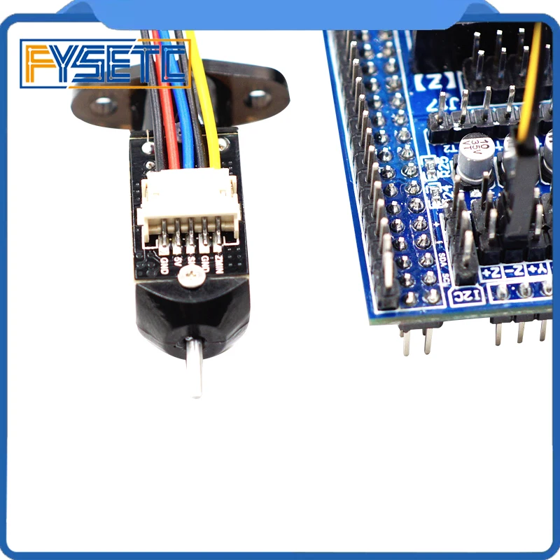
The main drawback of this sensor type is that it is slower compared to the other non-contact types. While there is only a few seconds difference per probe point, this can add up if you are doing a 7X7 (49 points) or greater grid pattern. The good news is that in Marlin 2.0 and newer, there is a feature called HSMode which allows you to probe nearly as fast as the others. The next issue is that it contains moving parts so, in theory, there is more that can break on the sensor. Luckily, the mechanism is extremely simple so there is almost no chance of it actually failing. The new plastic probe tips are also made to bend so if you accidentally crash it, you can simply bend the plunger back in place and get back to printing.
All testing was done with three brand new Prusa MK3S printers modified to accommodate the different sensor types.
Accuracy:
We wanted to test how well the three probes could continually reproduce a 0.24mm, single layer print without any other variables changing such as temperature or build surface types. We tested this by using micrometers to adjust the z-offsets until all three printers were printing a true 0.24mm thick first layer. Once dialed in, we printed the test print 5 more times and measured the thickness in several spots using the same micrometers. All of the probes were able to reproduce a 0.24mm thick first layer consistently without any deviation. If the inductive and capacitive probes are more accurate, they did not translate into any real-world results. Our conclusion: in a controlled environment all three options will provide accurate readings.
Winner: Tie (Inductive/Capacitive/Physical-Hall Effect)
Versatility:
Our expectations: set the z-offset once and continually get a perfect first layer, regardless of the build surface type or ambient temperature. When you have several printers, you don't want to have to think about tweaking z-offsets every time your printer setup changes. This saves both time and frustration which, in our opinion, is the most important function of a bed leveling probe.
On paper, the two non-contact sensors should be the most accurate. Their lack of moving parts and the sensing method give them a leg up (and was shown by Thomas Sanladerer on his YouTube comparison). However, when you throw in real-world variables such as different build surfaces and drastic temperature changes present in an enclosure, the Physical-Hall Effect type sensor comes out head and shoulders above the rest.
Similar to the previous accuracy test, we set our first layer height to 0.24mm and then printed an object that was only one layer thick. We then removed the print and measured it with micrometers and made adjustments until it was exactly 0.24mm. Once the z-offset was adjusted to produce a true 0.24mm first layer, we then heated the enclosure to 35°C and hit print without adjusting anything. The 3DM Touch was the only one that was able to reproduce the same 0.24mm first layer while the other two failed to have a successful first layer. We did this 4 more times and the results were the same each time. The non-contact sensors just weren’t able to give the same z-offset reading with the large change in temperature.
The next test was about switching between build surfaces. We did not test the inductive sensor as it can only sense metal and knew it wouldn’t be able to handle this task. For this test, we again adjusted the z-offsets on the two printers to produce a 0.24mm first layer using a spring steel build surface. After this, we then swapped out the spring steel build surface for a polypropylene plate. As expected, the 3DM Touch printed the same 0.24mm first layer while the capacitive (EZABL) sensor gave us a first layer height of 0.17mm which is an error of 30%. This is because even though the capacitive sensor can detect polypropylene, it detects it at a different distance than spring steel. If you plan on using different build surfaces, we recommend staying away from the inductive sensors as they will fail to detect everything except metal.
Winner: Physical-Hall Effect Sensor
Probing Speed:
Both non-contact sensors are considerably faster than the physical probe. They don’t have any moving parts so no time is required to cycle the probe up and down. As mentioned earlier, Marlin 2.0 has introduced HSMode for the 3DM Touch which has helped increase probing speed, however, even then it will still be ~10% slower to probe the same number of points. If probing speed is extremely critical in your application, an inductive or capacitive sensor might be the best choice for you.
Winner: Tie (Inductive/Capacitive)
Durability:
After testing each sensor type (multiple of each, over several months) none of them showed any signs of having issues with durability. Some argue that the 3DM Touch sensor has moving parts so it, in theory, could wear out. We are confident that your machine would need to be replaced long before the plunger mechanism wears out. The old BLTouch probes had metal tips that would get damaged if you crashed your machine but the newer ones all use “breakaway” plastic tips that deflect if crashed.
Winner: Tie (Inductive/Capacitive/Physical-Hall Effect)
Because the 3DM Touch is a lot more complex in its design, it tends to also be the most expensive. There are also very few manufacturers who produce them which is also a driving factor of cost. Quality capacitive and inductive sensors, on the other hand, can be found for less than $10. This is approximately a third of the cost of 3DM Touch-type probes. If you are on a tight budget and still want to add a bed leveling probe to your machine, both the capacitive and inductive sensors will be a great choice.
Winner: Tie (Inductive/Capacitive)
All three sensors seem to do a more than adequate job as long as you don’t plan on switching build surfaces or changing ambient temperatures drastically. Casual users who are on a tight budget will likely be extremely happy with either a conductive or inductive type sensor.
If you are a 3D printing “super-user” and have the extra budget, we would recommend the 3DM Touch as it requires the least amount of calibration in the long run. It handles everything from build surface changes to large temperature variation without ever needing to do any additional calibration.
Each user is going to have a different set of requirements for their printing needs. For us, the 3DM Touch made the most sense; for others, it may be a capacitive or inductive sensor. We hope that this article helps clear up any uncertainty about the various options available and will help you make an informed decision for your own needs. If you have any questions about areas we did not cover, please feel free to contact us and we will do our best to provide answers.
-3DMaker Engineering
Probe Configuration | Marlin Firmware
No matter how well you constrain, tighten up, and align the components of your 3D printer, there are bound to be imperfections in alignment that can negatively affect print quality. Among these imperfections, irregularities in bed-nozzle distance is one of the most problematic. After all, if the first layer doesn’t adhere to the bed then the rest of the print job is moot.
Marlin includes a “Bed Leveling” feature that compensates for these imperfections by taking measurements of the bed-nozzle distance at 3 or more points and then adjusting the nozzle position throughout the print so that it remains at a consistent distance from the bed.
Marlin allows you to take these bed measurements using nothing but a piece of paper, but for an improved experience the best option is to install a bed probe (also called a “Z probe”).
Bed Probes
Marlin 1.1 supports a wide variety of probe types:
- Simple switch (
FIX_MOUNTED_PROBE) - Switch on a servo arm (
Z_ENDSTOP_SERVO_NR) - Switch on a solenoid (
SOLENOID_PROBE) - Inductive probes (
FIX_MOUNTED_PROBE) - BLTouch - and clones (
BLTOUCH) - Sled-mounted probe (
Z_PROBE_SLED) - Allen-key delta probe (
Z_PROBE_ALLEN_KEY) - No probe (
PROBE_MANUALLY)
Bed Leveling Methods
Marlin includes various methods of probing and leveling:
- “3-Point” probes a triangle to determine the height and tilt of the bed plane. During printing the nozzle is adjusted in X, Y, and Z, so you can even print on a badly-tilted bed.
 However, this method requires a very flat and even surface.
 - “Linear Grid” probes a square grid (as much as possible on
DELTA) to determine the height and tilt of the bed. After that it works just the same way as 3-point leveling. - “Bilinear Grid” probes a grid in the same manner as Linear Grid, but during printing the Z axis is adjusted according to bilinear interpolation between the measured points. This allows the printer to compensate for an uneven surface,
- “Mesh Bed Leveling” works in the same manner as “Bilinear Grid” but takes different
G29parameters. (This feature is superseded by combining the manual probe option with bilinear leveling, and will not be included in future versions of Marlin.) - “Unified Bed Leveling” combines elements of bilinear and planar leveling and includes extra utilities to help improve measurement accuracy, especially for deltas. See (link) for an article specifically about this feature.
Configuration
1.
 Z Probe Pin
Before configuring any bed probe be sure to read its documentation and the documentation for your electronics. Make sure you know to which pins the probe will be connected. Marlin provides reasonable defaults, but they will not apply to every situation.
In general, on deltabots the probe should be connected to the unused Z-Min endstop pin (if there is one). On machines that use Z-min for an endstop, the Z-Max pin is recommended next, so this is set as the default alternative on most boards.
- If the probe is connected to the Z-Min pin, enable
Z_MIN_PROBE_USES_Z_MIN_ENDSTOP_PIN. - For Marlin 2.0.5.2 and earlier, if the probe is connected to any other pin, enable
Z_MIN_PROBE_ENDSTOP. - The probe-specific pin is defined with
Z_MIN_PROBE_PIN. Most boards have a default, but it can be overriden in the configuration.
2. Probe Type
What kind of probe do you have?
-
FIX_MOUNTED_PROBEUse this option for a fixed switch or inductive probe. This is the option to select if the nozzle itself is used as the probe.
 -
Z_ENDSTOP_SERVO_NREndstop switches are inexpensive, and some printer kits include one or two replacement parts. So one popular probe type mounts an endstop switch on a servo-driven arm. Set this option to0for a servo-probe connected to the first servo plug,1for the next servo plug, etc. Set the servo’s deployed/stowed angles with theZ_SERVO_ANGLESsetting. -
SOLENOID_PROBESelect this option for a switch mounted on a solenoid. -
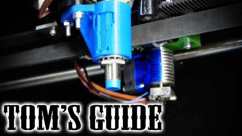
BLTOUCHThe BLTouch by ANTCLABS is a compact probe specifically designed for use on inexpensive 3D printers. It uses a Hall effect sensor to detect the movement of a metal pin that can be magnetically extended and retracted. The BLTouch connects to the servo pins which function to send commands to the probe. -
Z_PROBE_SLEDThis option applies to a switch mounted on a “sled” that can be docked to the end of the X axis. The X carriage can pick up this sled, use it to perform probing, and put it back when done.
 -
Z_PROBE_ALLEN_KEYThis is a popular solution on deltas. A spare Allen key is used with an endstop switch to make a probe that’s deployed and stowed by turning the key 90 degrees. You can either deploy and stow the key manually or configure movements that bump the key against some fixed point. Options for this type of probe are included in the delta example configurations that come with Marlin. -
PROBE_MANUALLYThe bed-nozzle distance can be measured without a probe by following amanual procedure. The nozzle moves to each point and pauses. You adjust the Z height so that the nozzle is touching the bed. Once the Z height is adjusted, you tell the machine to go to the next point. Continue until all points are probed. This option can be used with all Auto Bed Leveling options except UBL, which is freestanding.
3.
 Other Probe Options
-
LCD_BED_LEVELINGprovides a guided process to assist withPROBE_MANUALLY(or Mesh Bed Leveling). Without this option you must sendG29to move to the next point andG1(or buttons in your host software) to adjust the Z axis. -
Z_MIN_PROBE_ENDSTOP_INVERTINGshould be set totrueif your probe uses normally-open (NO) switches. Normally-closed switches are recommended because they have the appropriate failsafe state and are less prone to false positives. -
ENDSTOPPULLUP_ZMIN_PROBEmay be used if you need to disable the endstop pullup for some reason, such as having an external pull-down resistor on a normally-open switch. -
USE_ZMAX_PLUGmust be enabled if the probe is connected to the Z-Max endstop pin.USE_ZMIN_PLUGmust be enabled if the probe is connected to the Z-Min endstop pin. Et cetera, et cetera.
everything you need to know
3DPrintStory Reviews BLTouch sensor for 3D printer: everything you need to know
Automatic table calibration is a fairly common feature in desktop FDM 3D printers. However, most 3D printers with automatic table calibration use a non-contact inductive sensor, which is easy to install, operate and configure. These inductive sensors work well with metal 3D printer tables, but tables made from other common materials such as glass are virtually invisible to inductive sensors.
Perhaps it is because of this lack of inductive sensors that many people hear about BLTouch sensors: if you need to use a non-metallic 3D printer slot base but need automatic calibration, these sensors are a great option.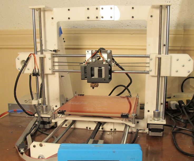 Another plus of these sensors is its high accuracy. BLTouch raw readings have one of the lowest standard deviations of any sensor type for automating 3D printer bed calibration.
In this article we will look at the BLTouch sensor, its advantages and how to use it for a 3D printer (by the way, there are many clones of BLTouch sensors, but the original design belongs to Antclabs from South Korea).
What is a BLTouch sensor?
According to Antclabs, the original manufacturer of the sensor, "BLTouch is an automatic table calibration sensor for 3D printers that can accurately measure the angle of the table surface." This sensor works on any type of surface, be it metal, glass, wood and others.
The 3D printer table tilt level sensor itself has a rather complex design. It consists of a microcontroller, a solenoid switch and a handpiece that is in direct contact with the table. The original BLTouch uses a Hall sensor for high accuracy, and this sensor, combined with the physical handpiece, allows it to be used with many types of tables.
In a sense, this sensor is equivalent to a microswitch mounted on a servo. When the tool head is lowered to "return" the nozzle in the Z-axis, the table pushes the tip slightly up, the Hall sensor is activated, and then the tool head rises.
TheBLTouch is one of the most accurate and reliable sensors available, so it's no wonder some manufacturers like MakerGear and CraftBot use this device on their high end 3D printers.
Now that we know exactly what we're dealing with, let's compare the BLTouch with the other two types of sensors.
Different types of sensors for automatic 3D printer table calibration
Inductive sensor
The key difference between inductive sensor and BLTouch is that the BLTouch sensor physically touches the table during the calibration process. The inductive sensor uses currents induced by magnetic fields to detect nearby metal objects, so there is no direct physical contact with the table.
But therein lies the problem: induction sensors only work with metal tables, as they only work when they come into contact with metal.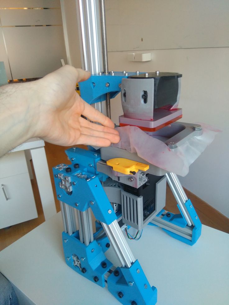 So if you are using glass, then this type of sensor will not work for you.
Microswitch (mechanical limit switch)
Don't discount the old-fashioned physical microswitch either. Compared to the BLTouch, this sensor is less accurate and possibly less reliable in the long run because the measurement is dependent on physical parts that can wear out over time.
However, these mechanical switches outperform other options when it comes to cost and ease of setup. Since mechanical switches are very simple to implement, easy to set up and cheap, they have found quite a wide application.
Alternatives
Pinda Probe
Pina Probe is a sensor developed by Prusa Research which is an induction sensor with a thermistor to account for changes in bed temperature. The Pinda probe is specially designed for the Prusa line of 3D printers, which have special dot-mounted calibration markers on the table that help with alignment and skew correction.
This is said to be a very accurate sensor for 3D printers, and although there aren't many numbers on the internet, the reviews seem to be positive.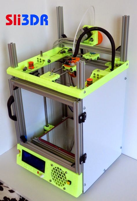 So it is worth considering that this is a good option if your 3D printer has a metal table.
Ezabl Pro
Ezabl Pro is a capacitive sensor manufactured. It comes with a connection board that uses an optical isolator to prevent high voltage damage to the motherboard in case of connection errors.
In terms of accuracy, it can measure to one thousandth of a millimeter, which is what 3D printers need. Ezabl Pro also has useful features such as double shielding that prevents any interference from other signals.
The main disadvantage of Ezabl Pro is the cost, which is about 65 dollars. But this sensor can work with glass tables.
Piezo Sensors
Piezo Sensor uses the piezoelectric effect to detect changes in force, pressure or strain and convert those changes into an electrical impulse. Precision Piezo is one of the few companies in the UK that makes piezo sensors for 3D printers. They have an accuracy close to 7 microns, which is pretty accurate for a 3D printer.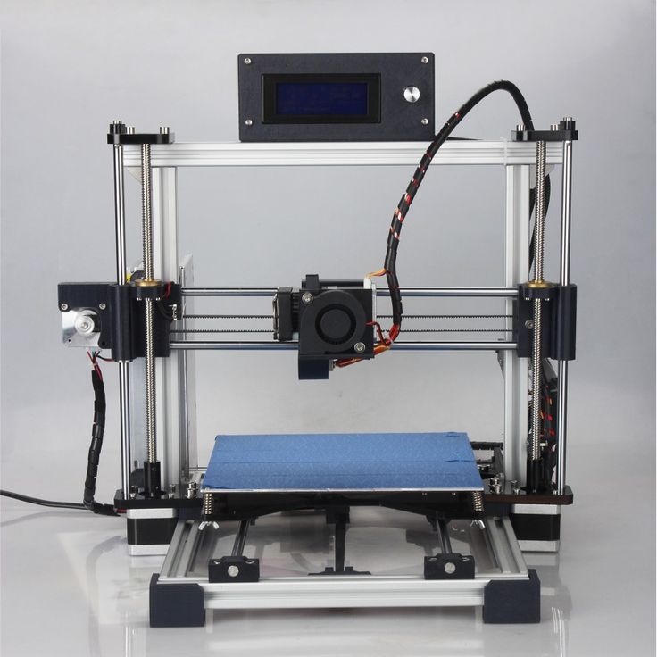
The advantage of the piezoelectric sensor is that a nozzle can be used as a sensing element without the need for additional components. In addition, a piezoelectric sensor can be placed on the print head or under the pressure platform. As for the price, it is in the same range as BLTouch.
BLTouch Sensor Setup Basics
Before you start modifying your 3D printer for BLTouch, you need to work through the following points.
Mounting the sensor
The BLTouch sensor must be installed as close to the print head as possible. You can find many designs available for download on the internet. If you would like to design the mounting structure yourself, be sure to read the BLTouch documentation to take into account the overall dimensions of the sensor.
Some users have experienced a problem where the nozzle hits the table on one side and prints perfectly on the other. The reason for this is that the BLTouch is mounted at an angle to the nozzle.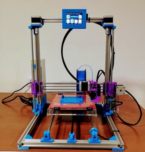 Therefore, when designing and installing equipment, make sure that the BLTouch is mounted perfectly at right angles and aligned with the nozzle.
After installing the sensor, be sure to record the distance between the BLTouch sensor and the nozzle center in both the X and Y directions.
3D Printer Firmware Configuration
To run BLTouch, you will need to change the 3D printer firmware in several places.
We used Marlin firmware version 1.1.9 which was updated in March 2020. Enter the marlin.ino file and go to the configuration.h tab.
The first step is to activate the BLTouch sensor by declaring it. Remove the two slashes to uncomment the define statement:
#define BLTOUCH
The next step is to set the BLTouch offset using the X and Y distances you should have measured when you installed the sensor. Z-shifting may seem like a more complicated procedure, as the BLTouch probe protrudes below the nozzle for direct measurements. You will need to find the distance between the sensor and the end of the nozzle when the sensor is fully extended.
Also, since the probe goes below the nozzle, the offset must be negative. We recommend setting it to around -2.5 for safe first runs and then adjusting. You need to change the values of the following lines to match your numbers:
#define X_PROBE_OFFSET_FROM_EXTRUDER 30 // X offset: -left + right [nozzles] #define Y_PROBE_OFFSET_FROM_EXTRUDER 20 // Y offset: -front + back #define Z_PROBE_OFFSET_FROM_EXTRUDER -2.5 // Offset Z: -below + above
After you're done with the offset, you'll need to choose a table alignment type. You can choose from five different compensation methods, below we will give an example using the bilinear method as it is easy to get started with.
To select the appropriate option, uncomment it by removing the slash. Please note that only one option can be left without comment. Your code should look something like this:
//#define AUTO_BED_LEVELING_3POINT //#define AUTO_BED_LEVELING_LINEAR #define AUTO_BED_LEVELING_BILINEAR //#define AUTO_BED_LEVELING_UBL //#define MESH_BED_LEVELING
You can also set the number of mesh points that you will base your calibration on. Default is 9points that form a 3 by 3 grid along the x and y axes. The number of points can be increased for more accurate results, but keep in mind that the probing time will also increase proportionally.
#if ENABLED (AUTO_BED_LEVELING_LINEAR) || ENABLED (AUTO_BED_LEVELING_BILINEAR)
// Set the number of grid points per size.
#define GRID_MAX_POINTS_X 3 #define GRID_MAX_POINTS_Y GRID_MAX_POINTS_X
Testing
After setting up the firmware, you will need to check if the BLTouch is working properly by doing a basic test. Once it's complete, you can start adjusting the Z offset. There's a great video from 3DMakerNoob that walks you through the process step by step.
Slicer setup
Be sure to add the G29 command to your Gcode right after the G28 command.
Troubleshooting
Troubleshooting
The creators of the original BlTouch at Antclabs mentioned that the original sensors come with a QR code built into the circuit board on the back. Other Chinese manufacturers, called TL Touch and 3D Touch, are also known to produce lower quality products, resulting in poorer quality. When buying online, be sure to purchase from one of the authorized resellers that are listed on the Antclabs website.
Known Issues with BLTouch Sensor
The latest version of BLTouch V3 had issues with Creality printers where it did not work properly. The Marlin firmware developers worked closely with Antclabs and determined that certain changes needed to be made to the firmware.
An excellent tutorial video on how to fix this problem was made by Teaching Tech. After making changes, many users finally solved the problem.
Disadvantages of BLTouch
Although the BLTouch is an extremely accurate level sensor, it also has several disadvantages.
When using the BLTouch, it is important that there is no debris on the surface of the bed.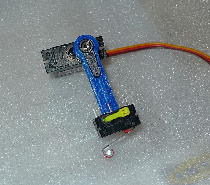 A mechanical sensor detects the surface of the table and any damage or debris on the surface will result in inaccurate readings.
The BLTouch is also known to suffer from interference from currents in the hot end heater wires. This interference causes incorrect BLTouch readings. The Marlin firmware has a special line of code that will help you turn off the heaters while the sensor is triggered. To activate it, find and uncomment the following:
#define PROBING_HEATERS_OFF
3D Printing Tech expands SLS fleet to six MfgPro230 xS SLS machines from XYZprinting
"Details matter" is a fundamental principle in 3D printing technology. The MfgPro230 xS SLS 3D printer has proven to be a reliable workhorse, consistent in detail and reliable in performance. This allows us to focus on what matters to our customers, which is why we decided to expand our SLS fleet with XYZprinting. " - 3D Printing Tech Co-Founder, Josh Stover
BACKGROUND
3D Printing Tech is a solution provider for the quick service industry.
3D Printing Tech offers new design, scanning, modeling, 3D modeling and creative consulting; in addition to numerous forms of 3D printing technology, to help customers navigate the transformation and creation of 3D digital models, physical objects.
CALL
During the first few weeks of the COVID-19 pandemicA 3D printing specialist received a call from a local doctor and Lab owner with a simple question: “Can you 3D print probes for COVID testing?”, and this began the mass production of probes using SLS printing. A group was formed, involving a number of leading universities and medical systems, with the initiative to develop and prove that a probe could be 3D printed and function just like a traditionally made one. SLA, MJF, and even FDM/FFF were the methods others were promoting for probes, but 3D Printing Tech, fully understanding the scalable possibilities of SLS printing, decided to move forward in this direction. As demand grew, it quickly became clear that XYZprinting's only 3D Printing Tech SLS machine would not be able to handle the volume required. Thousands and thousands of products had to be produced weekly.
SOLUTION
MfgPro230 xS SLS proves reliable
MfgPro230 xS from XYZprinting has proven to successfully assemble thousands of probes simultaneously. 3D Printing Tech introduced 5 more SLS machines in July 2020, enough to meet product demand and 3D printing service demand, at least for now.
RESULTS
High production for short-term production
The scalability of SLS printing and the cost of the MfgPro230 xS enabled 3D printing technology not only to boost the production of a large number of coronavirus prevention probes, but also to create the largest production capacity for short-term production in the South eastern United States.
FORECAST
The MfgPro230 xS value for money has allowed us to expand our business significantly.