Paste extruder for 3d printer
Paste Extruder | Hackaday
October 14, 2021 by Tom Nardi
While we don’t often see them in the hobbyist community, 3D printers that can extrude gels and viscous liquids have existed commercially for years, and are increasingly used for biological research. [Ahron Wayne] has recently been working with such a printer as part of a project to develop a printed wound dressing made of honey and blood clotting proteins, but for practice purposes, wanted to find a cheaper and more common material that had similar extrusion properties.
The material he settled on ended up being common toothpaste. In the video below you can see him loading up the cartridge of a CELLINK INKREDIBLE+ bioprinter with the minty goop, which is then extruded through a thin blunt-tip needle by compressed air. After printing out various shapes and words using the material, often times directly onto the bristles of a toothbrush, he’s come up with a list of tips for printing similarly viscous substances.
First and foremost, go slow. [Ahron] says the material needs a moment to contract after being extruded if it’s going to have any hope of supporting the next layer of the print. Thick layer heights are a necessity, as is avoiding sharp curves in your design. He also notes that overhangs must be avoided, and though it probably goes without saying, clarifies that an object printed from toothpaste will never be able to support anything more than its own weight.
In addition to the handful of legitimate DIY bioprinters that have graced these pages over the years, we’ve seen the occasional chocolate 3D printer that operated on a similar principle to produce bespoke treats, so the lessons learned by [Ahron] aren’t completely lost on the hacker and maker crowd. Who knows? Perhaps you’ll one day find yourself consulting this video when trying to get a modified 3D printer to lay down some soldering paste.
Continue reading “3D Printing Toothpaste In The Name Of Science” →
Posted in 3d Printer hacks, Medical HacksTagged bioprinter, extrusion, paste extruder, toothpasteJune 18, 2021 by Al Williams
While refitting a 3D printer for food printing isn’t really a new idea, we liked the detailed summary that appeared from a team from the University of Birmingham which converted an i3 clone printer to use a syringe extruder.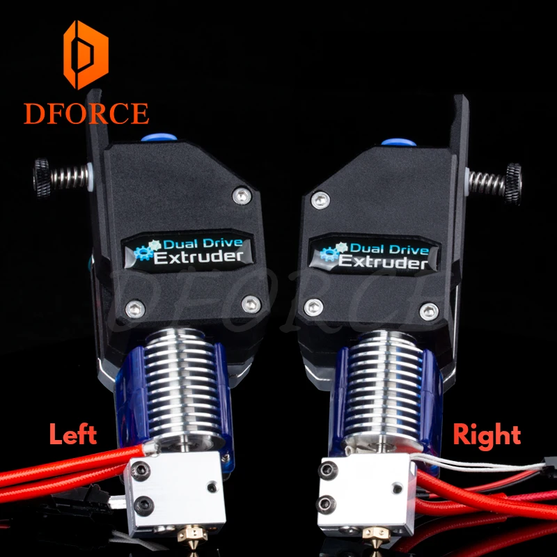
The syringe in question was meant for veterinarian use and is made of metal. The paper suggests that the metal is a better thermal conductor, but it was’t clear to us if they included a heating element for the syringe. In the pictures, though, it does appear to have some insulation around it. In any case, we imagine a metal syringe is easier to keep clean, which is important if you are depositing something edible.
Continue reading “3D Printing Food University Style” →
Posted in 3d Printer hacksTagged 3d printing, 3d printing food, paste, paste extruder, syringeFebruary 18, 2021 by Tom Nardi
It’s recently come to our attention that a company by the name of Nourished has carved out a niche for themselves by offering made-to-order gummy vitamins produced with their own custom designed 3D printers. Customers can either select from an array of pre-configured “stacks”, or dial in their own seven layers of gelatinous goodness for a completely bespoke supplement.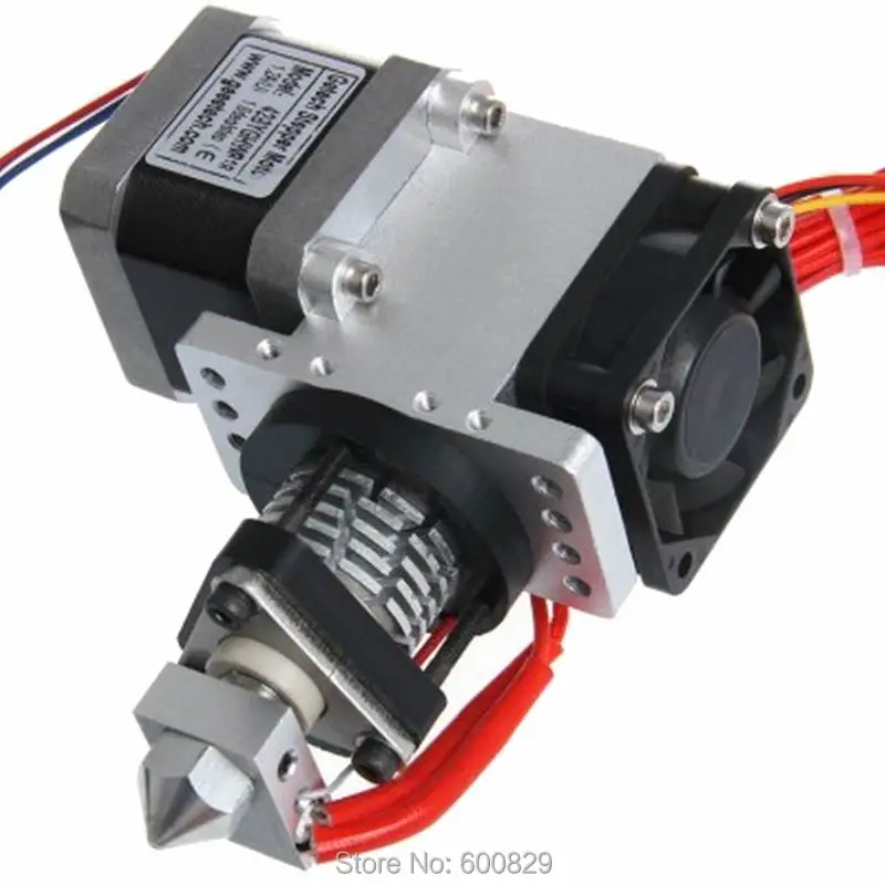
Now we can’t vouch for whether or not taking a custom supplement like this is any better than just popping a traditional multi-vitamin, but we’ll admit the hardware Nourished has developed is pretty interesting. As briefly seen in the video after the break, large syringes are filled with the seven different vitamin suspensions, and then loaded into what appears to be a heated chamber for extrusion. This is not unlike other food-grade 3D printers we’ve seen, such as the Cocoa Press.
It looks like all of the syringes are being depressed simultaneously with a plate and a pair of beefy lead screws, so it seems the order in which the layers are placed down must be different for each nozzle. A blog post on the company’s site from early last year shows a wildly different machine being used to produce the vitamins, so either their core technology is changing rapidly, or perhaps the printer being used depends on whether they’re running off the customized stacks versus the standard formulations.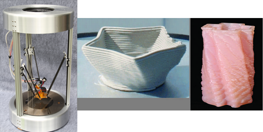
Interestingly, this is very similar to a concept floated by the U.S. Army’s Combat Feeding Directorate (CFD) back in 2014. They reasoned that a 3D printer could be used to produce meal bars that were customized for each soldier’s personal nutritional needs. Being largely impractical for the battlefield, the program didn’t get very far. But thanks to consumers who are willing to pay the premium that Nourished is charging for this service, it seems the idea has turned into a lucrative business model.
Continue reading “Custom 3D Printed Vitamins Are Just A Few Clicks Away” →
Posted in 3d Printer hacks, hardwareTagged 3d printing, food printer, paste extruderMarch 5, 2018 by Tom Nardi
What do you get when you combine oven-baked mussels and sugar beets in a kitchen blender? No, it isn’t some new smoothie cleanse or fad diet. It’s an experimental new recyclable 3D printing material developed by [Joost Vette], an Industrial Design Engineering student at Delft University of Technology in the Netherlands.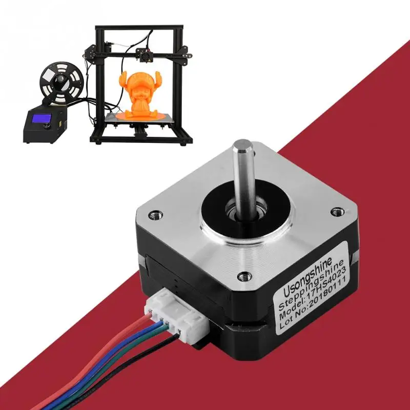 While some of the limitations of the material mean it’s fairly unlikely you’ll be passing over PLA for ground-up shellfish anytime soon, it does have a few compelling features worth looking into.
For one thing, it’s completely biodegradable. PLA is technically biodegradable as it’s usually made primarily of cornstarch, but in reality, it can be rather difficult to break down. Depending on the conditions, PLA could last years exposed to the elements and not degrade to any significant degree. But [Joost] says his creation degrades readily when exposed to moisture; so much so that he theorizes it could have applications as a water-soluble support material when printing with a multiple extruder machine.
What’s more, after the material has been dissolved into the water, it can be reconstituted and put back into the printer. Failed prints could be recycled directly back into fresh printing material without any special hardware. According to [Joost], this process can be repeated indefinitely with no degradation to the material itself, “A lot of materials become weaker when recycled, this one does not. ”
”
So how can you play along at home? The first challenge is finding the proper ratio between water, sugar, and the powder created by grinding up mussel shells necessary to create a smooth paste. It needs to be liquid enough to be extruded by the printer, but firm enough to remain structurally sound until it dries out and takes its final ceramic-like form. As for the 3D printer, it looks like [Joost] is using a paste extruder add-on for the Ultimaker 2, though the printer and extruder combo itself isn’t going to be critical as long as it can push out a material of the same viscosity.
We’ve seen a number of DIY paste extruder mods for 3D printers, which is a good starting point if you’re getting sick of boring old plastic. Before long you might find yourself printing with living tissue.
[Thanks to Mynasru for the tip]
Posted in 3d Printer hacks, chemistry hacks, green hacksTagged biodegradable, paste extruder, recycling, ultimakerDecember 27, 2017 by Al Williams
Most of our 3D printers print in plastic. While metal printing exists, the setup for it is expensive and the less expensive it is, the less impressive the results are. But there are other materials available, including ceramic. You don’t see many hobby-level ceramic printers, but a company, StoneFlower, aims to change all that with a print head that fits a normal 3D printer and extrudes clay. You can see a video of the device, below. They say with some modifications, it can print other things, including solder paste.
The concept isn’t new. There are printers that can do this on the market. However, they still aren’t a common item. Partially, this is a cost issue as many of these printers are pricey. They also often require compressed air to move the viscous clay through tubes. StoneFlower has a syringe pump that doesn’t use compressed air.
Continue reading “Your 3D Printer Could Print Stone” →
Posted in 3d Printer hacks, Crowd FundingTagged 3d printing clay, ceramic, clay, paste extruder, porcelain, syringe pumpLow-Cost, Modular Modification to a Desktop 3D Printer for General Purpose Gel/Paste Extrusion & Direct Ink Writing
New Results
D. J. Leech, S. Lightfoot, D. Huson, A. Stratakos
doi: https://doi.org/10.1101/2021.03.10.434735
- Abstract
- Full Text
- Info/History
- Metrics
- Preview PDF
Abstract
We propose a design for a simple paste extruder modification that can be used for the selective deposition and patterning of gels and pastes, using a desktop 3D printer as the primary platform. This technology has found use with a variety of materials in seemingly disparate fields, including the printing of ceramics, food and biological materials, each with a variety of material-specific solutions to enhance printability. However, we focus on a syringe-pump driven system that is simple, low-cost, modular, easily assembled and highly modifiable with a low barrier of entry in order to maximise the generalisability and range of printable materials.
1 Introduction
The precision positioning and selective deposition possible with extrusion based 3D printing platforms has relied heavily on the use of known and very specific filament formulations, such as PLA [1] and ABS [2], that allow for robust and versatile designs.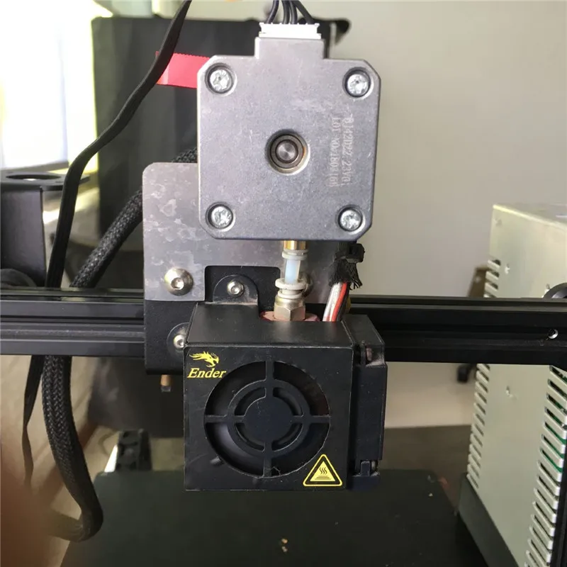 However, many recent subsets of the field of additive manufacture have focused on the design and deposition principles of the process, whilst varying the printing materials to include biomaterials [3, 4, 5], glass [6, 7], a variety of other polymers [8, 9], metals [10, 11], concrete [12, 13], food [14, 15], and ceramics [16, 17].
The latter two examples are particularly interesting in their overlap with fused deposition modelling (FDM) printing techniques, due to their long history with other extrusion-based techniques, particularly within an industrial setting. However, while these examples historically work with relatively large amounts of material, bioprinting for instance tends toward small feature sizes and low material content, focusing on the building of structure from traditionally soft materials with high precision and maintaining any cell content within the ink [3]. As such, components of extrusion and extrusion-centred design and manufacture arise in a broad range of fields and approaches, in which materials in a reservoir are shaped, formed and built whilst under pressure caused by a die or nozzle.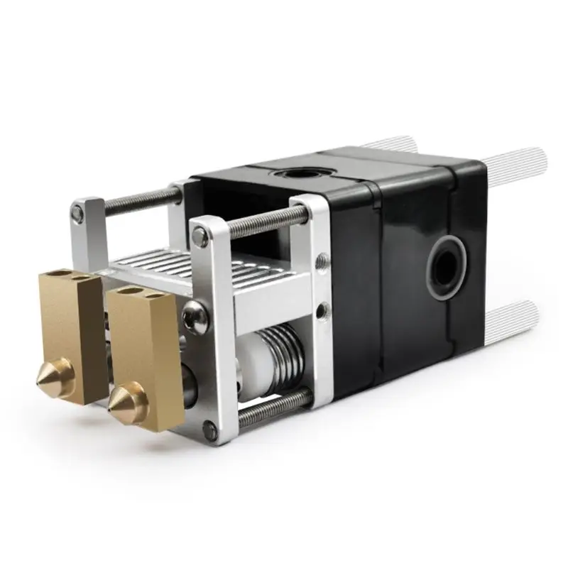 The name of this process can vary depending on the field, however we use material extrusion [18] or direct ink writing [19] as a ‘catch-all’ term to describe both the extrusion technique and the selective deposition enabled by modern 3D printing platforms. In terms of printable materials, we focus on a range of pastes or gels - generic terms to describe any viscous or relatively slow-flowing material.
Similar material generic extruders, utilise the selective XYZ positioning of a 3D printing platform, guiding a nozzle that is fed by a reservoir. The primary differences between these systems being:
The method of feeding the material from the reservoir to the nozzle.
Whether the reservoir system is mounted directly to the nozzle or fed via a connecting tube.
The dimensions used (reservoir size, nozzle diameter, connector dimensions etc.)
Any material specific optional upgrades (heating, cooling, enclosures etc.)
As mentioned, these systems allow for a large range of materials to be printed, however they are often subject to the same issues, including slow printing speeds, small reservoir sizes, requirements provided by the use of specific printer platforms, poor stability of printed artefacts, extensive stringing, single material extrusion and uneven extrusion [23].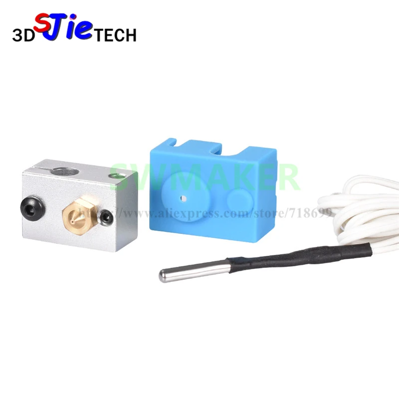 Multiple designs have been proposed in recent years to tackle specific issues within the paste extruder system and low-cost bioprinters with varying degrees of complexity and printer specific additions, including Ref. [20], [21], [22], [23], [25] [26], [27], [28], [29] and [30].
We propose a low-cost, generic and modular addition to a standard desktop 3D printer that allows for the deposition of a variety of gels and pastes. This design focuses on the need for a low-cost and low barrier of entry paste extruder add-on that is compatible with a variety of 3D printer platforms, achieved by containing the majority of the device separate from the printer, and placing very few restrictions on the nozzle, reservoir and connector dimensions. This generic approach to the dimensions allows for the possibility of scaling and means that both larger scale extrusion (up to cm width) and microextrusion should both be possible on this platform. Additionally, the simplicity of the design allows this modification to be made in the home, as well as in the lab, requiring no specialist assembly equipment beyond an FDM 3D printer.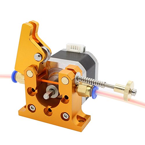
We additionally explore the material properties of a variety of inks and design a handful of test procedures that allow, without extensive outside equipment, for judgements of how to tune the printability of a particular ink recipe. Every material has a unique response and therefore may require differing formulations, temperature, pressure and tweaking of other parameters in order to make reproducible and controlled prints to the desired standard. We instead intend to produce a general guide for a generic paste extruder system, highlighting possible and common routes of exploration that may be used to enhance preliminary results for a variety of ink formulations.
2 Paste Extruder Design
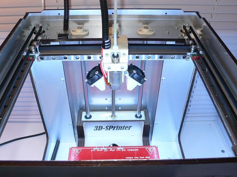
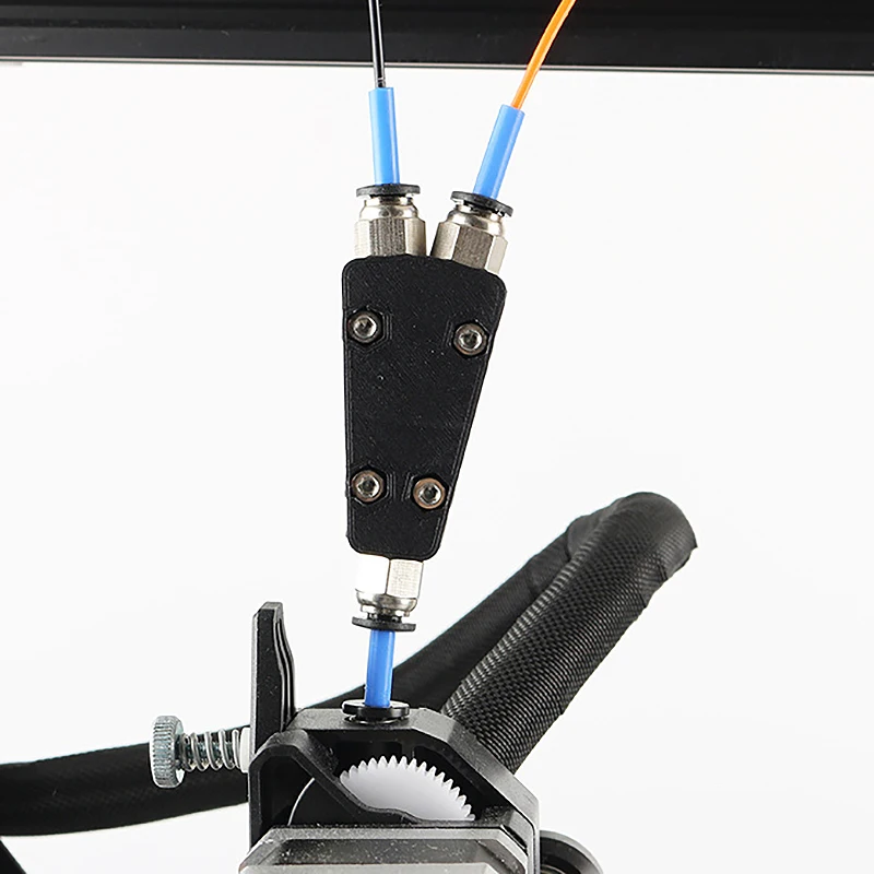
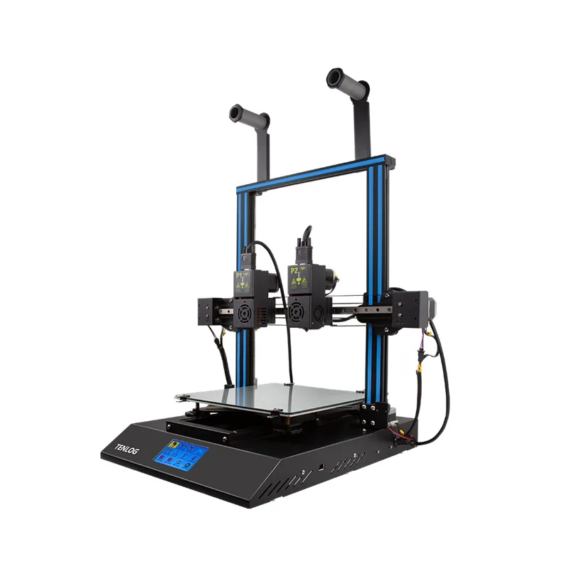
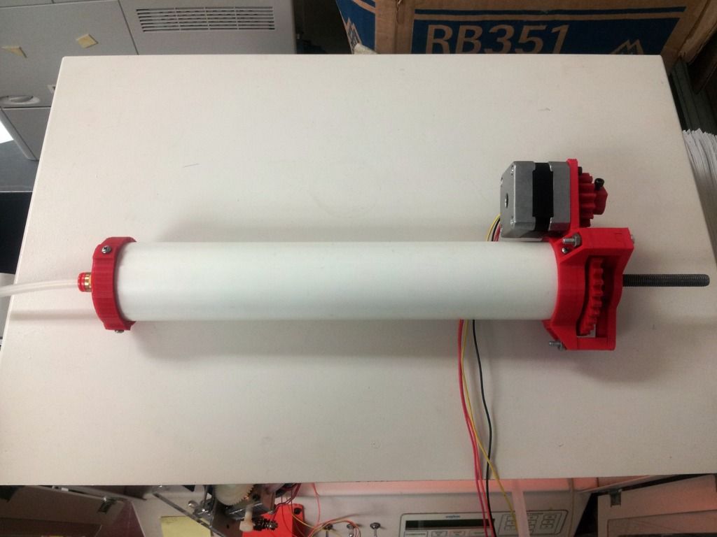
The paste extruder setup is intended to be modular and malleable, allowing for each component to be traded for other similar designs, depending on the needs of the user. This also means that the system can be quickly converted back into a traditional 3D printer platform with minimal effort.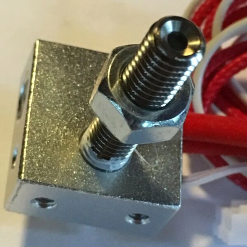 We use a simple setup comprising of a desktop 3D printer, syringe pump, connector tubing and a nozzle/nozzle holder combination. This can be seen in Fig. 1. Many of these components can be 3D printed and it is designed such that it can feasibly be attached to a wide range of desktop FDM 3D printers, as the only component in contact with the printer itself is the nozzle holder. We utilise the Creality Ender 3 as a low-cost and robust FDM platform, capable of running the material extruder.
Figure 1:
(a) Full paste extruder setup, including the syringe pump, connectors and nozzle, connected to Ender 3 3D printer. The plastic sheeting on the print plate is simply a non-stick baking sheet, for ease of removal of the print. (b) Nozzle holder design close up. Attaches directly the printing plate that holds printhead of the original 3D printer. The central holder design can be easily adjusted to accommodate a variety of connectors and tubing sizes.
Other printers may require modifications to the nozzle holder design or additional parts in order to work effectively.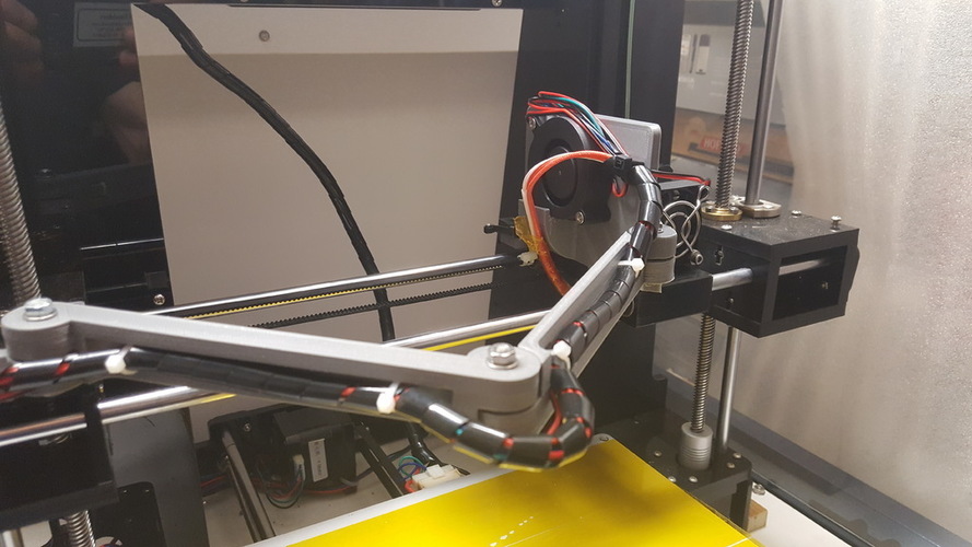 For instance, due to the choice of the Ender 3, we also recommend an additional 3D printed fan cover over the electronics housing to preclude the possibility of liquid inks leaving the print bed and entering the electronics housing. This may not be necessary on all printer types, however it is highly recommended that you search for any possible weakness points, prior to using the paste extruder.
Another useful, but non-essential, component to have is a sacrificial or non-stick surface on which to print. This makes removal of the print from the print bed far easier, reduces the amount of contact the original platform has with these paste inks and therefore increases the likelihood the printer could returned back to a traditional 3D printer state.
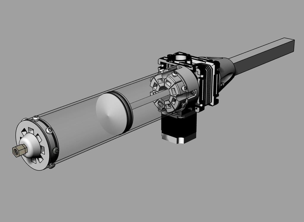
2.1 Syringe Pump
The ink reservoir and pumping system is a simple syringe pump, based on the impressive Poseidon Pump design [31]. This uses a stepper motor to drive a compressive wedge that acts on the syringe plunger. The body and driving wedge are both 3D printed, whilst the rest of the design is comprised of widespread components, found in both general hardware sellers and more specialist 3D printing storefronts.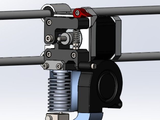 The wedge contains both either a flat surface or a small lip, upon which the syringe flange can be locked, in order to provide some amount of retraction to the syringe when driven in reverse. In addition, it provides an adjustable clasp so that a variety of syringe types and sizes can be used as the ink reservoir. In the original Poseidon design, the pump is driven by a Raspberry Pi/Arduino board, however here we instead power it via the desktop 3D printer using the extruder stepper motor JST connector, meaning any standard G-Code instructions can be interpreted by the paste extruder.
The pump is easily assembled, with both video and written instructions, and a low-cost bill of materials [31]. Alongside this, it is robust across multiple printing precision and layer heights, with only minimal finishing required to ensure all screw and bolt combinations fit. Finally, the ease of accessibility to the stepper motor means that it can easily be swapped out for other motors with additional torque or functionality.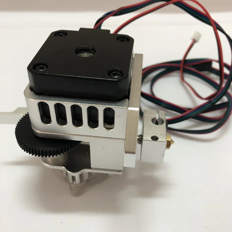 Unfortunately, the size of the original Poseidon Pump design is too large to be printed on the Creality Ender 3, however the design was adjusted by decreasing the height of the pump and therefore the separation between the stepper motor and the syringe holder and scaling the threaded and un-threaded rod required for assembly. This adjusted design is available on request from the corresponding author.
Other similarly produced syringe pump designs exist [32, 33, 34], alongside many commercial options, that could all easily be substituted in place of the Poseidon Pump.
2.2 Connector Tubing & Nozzle
The ink reservoir interfaces with the nozzle via male Luer lock connectors and plastic tubing. This locking system promotes even pressure during the extrusion process, but is not strictly necessary unless printing with at high pressures. A variety of sizing exists, however we find tubing of 5 mm in diameter has a simple interface with many common syringe sizes and types.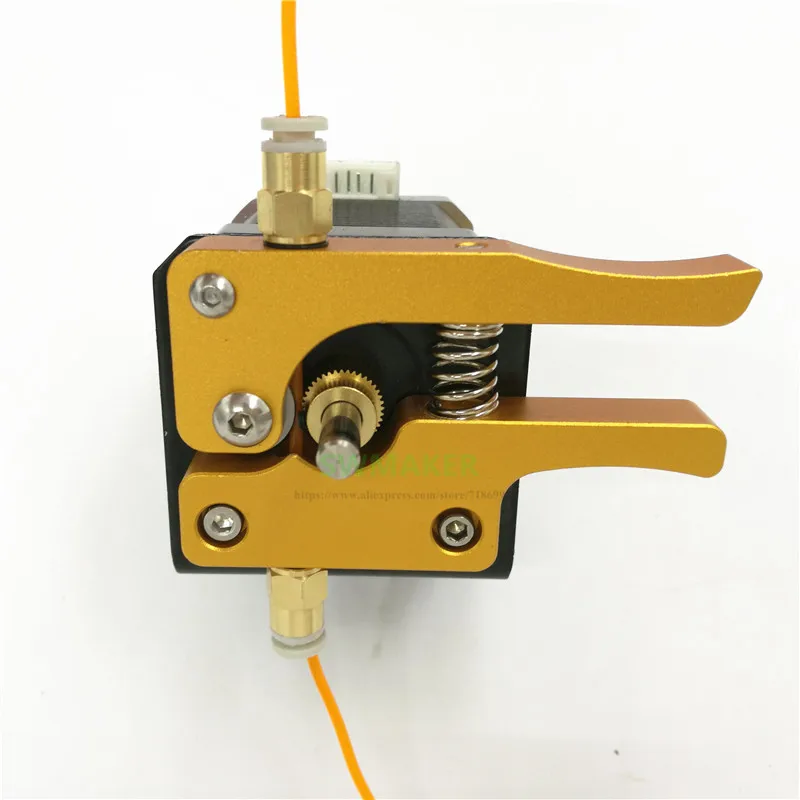 Whilst a seemingly low impact component of the design, this can have a large effect on the printability of an ink and the pressure required for extrusion. Ideally, the distance between the reservoir and the nozzle should be minimised to minimise the pressure required for extrusion. However. to ensure that the nozzle can cover the full dimensions of the printer, a minimum length is required. The inner diameter however can be varied and can therefore be made to accommodate a variety of particulate sizes and viscosities - a seemingly unprintable mixture can be made more accessible by shortening the distance between reservoir and nozzle and increasing the inner diameter. The geometry of the extrusion apparatus has long been known to affect the pressure felt by the extruder and the material and can therefore be a route to both increasing printability and further affecting the material properties during extrusion [35, 36, 37].
The nozzle portion comprises again of a male Luer lock connector, joining the tubing and nozzle and held in place by a 3D printed holder, included in the Supplementary Information. The holder can be raised and lowered easily to ensure a variety of nozzles can be accommodated and provides a straight-forward route for adjusting the relative z-coordinate, necessary when printing directly onto a raised substrate. Due to the generic Luer lock connection, a variety of nozzles can be attached, with both plastic and metallic director components.
3 General Ink Formulation
As with the software component, the formulation component of the design can vary depending on the material used and the needs of the user. Generally, the ink can be thought of as a mixture of the desired components and any additives that ensure printability. Additives could be materials that affect the viscosity, the material strength or the surface tension - however care has to be taken that these improvements aren’t at the cost of other factors that impact the printability. The desired components consist of the core material to be printed and any other functional additives - for example pigments or other optically functional components.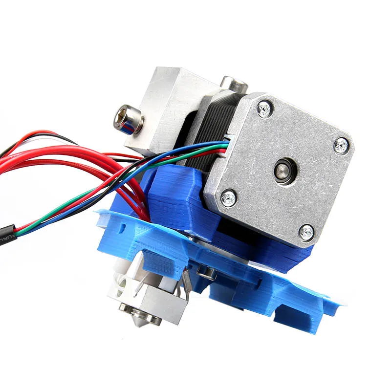 These components can also be processed to ensure more practical printability, including reducing particle sizes or chemically modifying the material. More often, care has to be taken in modifying these core materials to ensure that the final printed product retains the desired properties.
Table 1:
Some examples of printable ink formulations and the parameters varied in order to enable their printing. Note that all of these examples use differing printing equipment and may be over-simplifications of the full process - this list is intended to highlight explicitly mentioned commonalities in parameters that increase printability and the types of materials that can be printed.
External parameters can have a direct impact on the printability as well, including ambient airflow, pressure applied and the temperature of the ink, surroundings and printbed (the interplay between these three can be quite complex for certain materials).
4 Print Tests
Traditional tests of 3D printing platforms typically involve a complex design such as Benchy [23], in order to showcase the level of detail and complexity possible.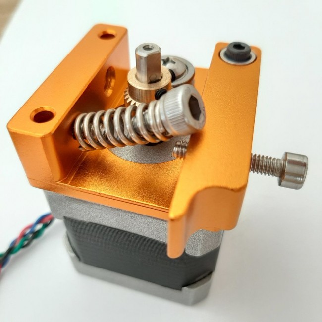 For paste extruder designs and viscous inks, a differing judgement of the overall quality must be made, that are dependent on criteria defined more by the desired output. However, we can make generic statements about the properties of the print using these tests that can then be used to further fine tune the printing parameters and improve the overall resolution, repeatability and printability.
4.1 Low-Lying Scaffold Design
The first test involves printing a simple line design that incorporates multiple 90° turns and a handful of layers, similar to the scaffold designs that are widely used in bioprinting [24, 26, 28]. This is designed to probe three main properties of the print:
The general thickness of a printed single line, with respect to the nozzle diameter.
Broadening of a 90° bend.
Possibility and common issues of layering.
An example of G-Code used to produce a design of this type has form
This can repeat giving multiple horizontal sections to the design and there-for a long observed print time and an increased chance of successful print.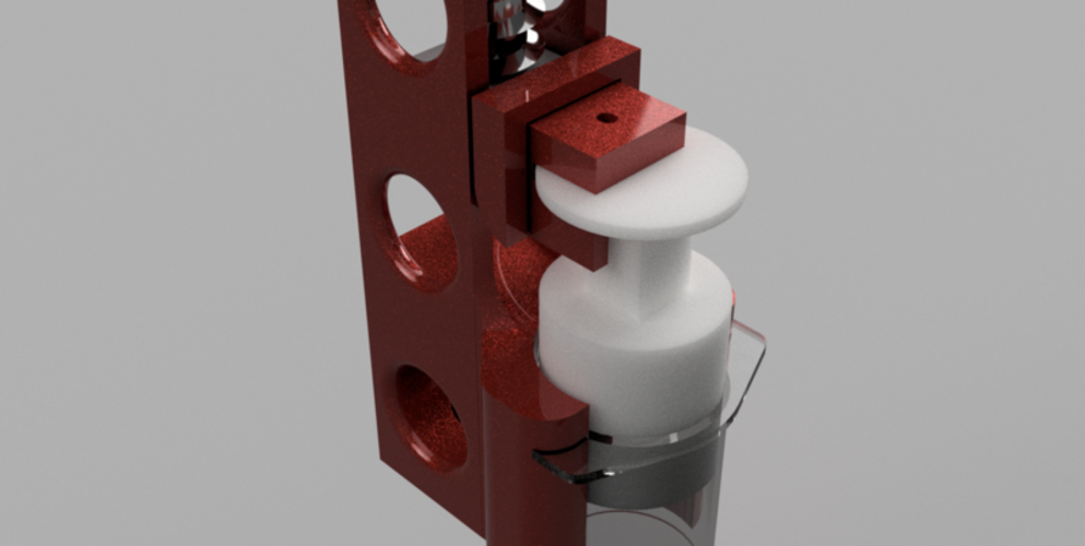 The opening M statements allow for cold extrusion and sets the extrusion coordinates to be relative, as opposed to absolute. This is particularly important for the syringe extruder where there is no longer a definitive zero, as this depends on the filling of the syringe reservoir and the amount of material available. The G1 commands are direct movements with (X, Y, Z) coordinates and an extrusion command E - the value following this command can initially be modified by hand so that it that it better aligns with the material response of the ink under pressure, the stepper motor in use and the geometry of the ink reservoir and connectors. This allows for a rough estimations of the required extrusion per mm steps.
Sample variations of this code are included in the Supplementary Information, for a variety of layer numbers. An additional Python script is included that takes in a coordinate set defining the maximal XY values of the scaffold, a extrusion multiplier and the number of 180 degree turns to incorporate per layer.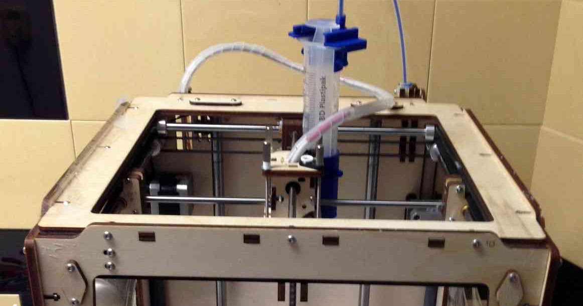 In this setup, each subsequent layer is rotated 90 degrees to the layer beneath.
The thickness of a single printed line, typically the horizontal sections, can be quantified as a function of the nozzle diameter as
where D is the thickness of the printed line and d is the nozzle diameter. It is best to obtain multiple measurements of D and average across them. Additionally, this value may change (sometimes dramatically) with increasing number of vertical layers, due to the flow and adhesion properties of the ink. As such, we define a complimentary value H, linked to the expected and measured overall height where N is simply the number of layers attempted. A combination of T and H values can be used to determine the flow of the ink post-deposition and therefore the feasibility of verticality for this particular formulation. Note however that even in standard 3D printing systems and materials such as PLA, this value does not tend towards one.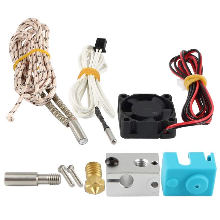 Standard values for PLA are in the region of H = 0.8.
Building from this, the broadening at the corners can be defined as
where dC is the expected corner length, based on the nozzle diameter, and DC is the measured corner length.
Note that for the same G-code these values will vary with the size of the ink reservoir, the ink formulation and, to a lesser extent, the connection between the syringe pump and nozzle - therefore it is important to keep these parameters constant during data collection.
4.2 Slump Test
Similar to the concrete slump test [47], we attempt to print a conical 3D object in order to further characterise the readiness and issues with a particular ink formulation in vertical layering. Traditionally, this test would involve a concrete mixture that would be gathered in a conical mold, with the mold removed carefully, to examine the loss of verticality or the ‘slump’, due to the competition between gravity and the setting of the mixture.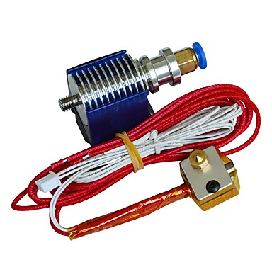
Here, we can build a series of conical shapes of differing heights and widths to examine both the slump and the frequency and types of errors in the stacking. These are most easily built in TinkerCAD, using the in-built cone feature, and can quickly produce a variety of designs through varying the height and We define both the ratio between the diameter of the cone at the base and top and their expected values,
where a subscript B represents a measurement at the base, a subscript T represents a measurement at the top of the cone and d represents the expected diameter at those points. Depending on the amount of the frequency of printing faults occurring, these values may not be rotationally symmetric and therefore an average across multiple angles may provide the most accurate representation. Additionally, depending on the material used, an accurate measurement of the top width may be impossible due to varied levels of slump around the print, as such we use the uppermost height of the cone as a third comparative term where hE is the expected value of the cone height.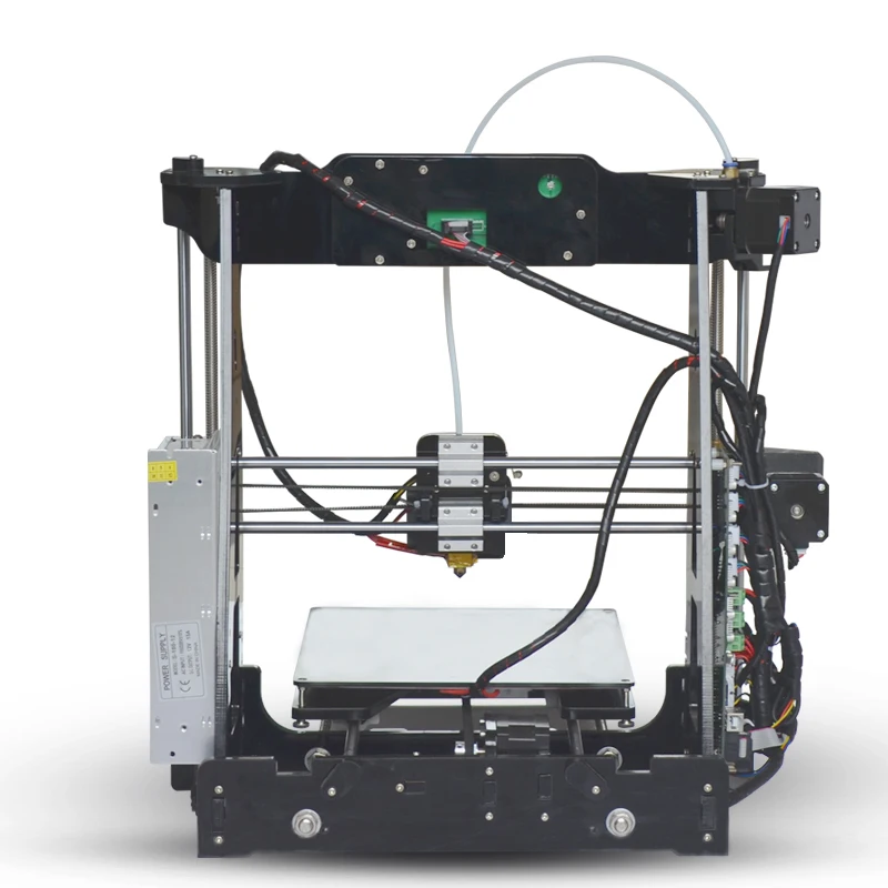 However, as with the scaffold design, the value of this ratio tends toward 0.8 for a traditional 3D printing materials such as PLA.
Table 2:
Scaffold design parameters and routes for tuning the print properties from these tests.
Variations in the height value are also useful for tracking any time-dependent properties of the printing ink, such as setting times and the separation of emulsions. Materials under a prolonged duration of pressure, such as those in the reservoir, can respond differently, particularly in terms of mixing and setting [48, 49], and produce a differing response in terms of the printed line width and height.
4.3 Step-Wedge Print
Other print features that are present and provide useful information about the print properties are more difficult to quantify. As such, a generic three-dimensional printed structure is useful for determining the suitability of an ink for more vertical prints, the interactions between differing types of print feature (walls/perimeters, infill, surface texture etc.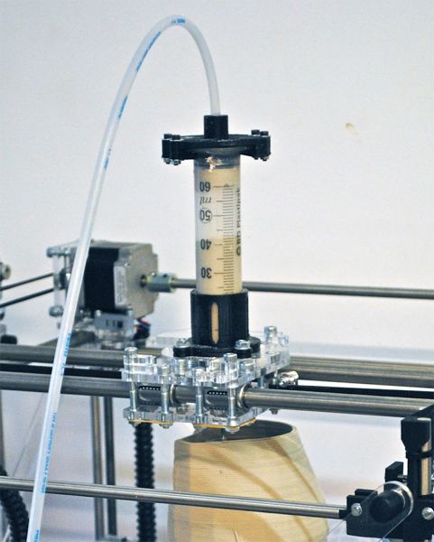 ) and other properties of the printer and slicer combination, like the print speed and rate of extrusion.
For this, we use a simple step-wedge design consisting of 10 adjacent steps, ranging from 1 mm to 10 mm in intervals of 1 mm. Each step is 1 cm x 1 cm in the XY dimension and provides a chance for printing both walls and infill at each layer and probing interaction formed by both vertically and horizontally neighbouring them. Note that the infill is always chosen to be 100%, simply because the vast majority of materials are unable to self-support themselves without the presence of material in the layer beneath.
These issues can be hard to troubleshoot, however generic print defects such as inconsistent wall thicknesses and overhangs can be reduced most commonly by reducing the printing speed and increasing the number of perimeters printed. Stringing is other common problem that can instead be mitigated by reducing the ‘travel speed’, the speed at which the nozzle moves when not printing.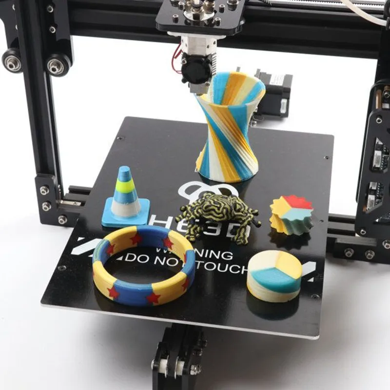 These problems are complex combinations of many parameters and may therefore not be possible to eliminate entirely.
Similar height and width measurements can be used for this print in order to determine the overall effects of setting and flow after deposition, however the previously described tests are more efficient in terms of time and material usage.
5 Case Studies
5.1 Gelatine
Gelatine represents an interesting test case, due to the prevalence of the material within bioprinting, most prominently as gelatine methacrylate (GelMA) [5, 50] or a gelatine/alginate composite [5, 51], as opposed to pure gelatine. These materials are favoured due to their enhanced mechanical properties via induced crosslinking through, for instance, the addition of UV irradiation and calcium chloride respectively [5]. Gelatine alone also physically crosslinks or sets upon cooling to room temperature [52] and the rate of setting is directly linked to the concentration and the Bloom of the sample (a measure of the setting strength). For a purely gelatine and water ink, 10-20wt% mixes of 250 Bloom gelatine heated to 40 - 50°c give a window of feasibility small enough to set once deposited but large enough to retain flow during the majority of printing. This attempts to balance the structure provided by the fast setting rate and the rate of extrusion, so that the material sets on the build-plate rather than in the reservoir. Failure of this system usually occurs due a mismatch of these competing effects leading to setting of the ink within the nozzle and reservoir, however we find the above parameters allow for volumes in the region of 10 - 20 ml of ink (or 5 - 10 print layers, depending on the design) to be extruded. Examples of gelatine prints can be seen in Fig. 3, including high-resolution and layered lines, filled two-dimensional shapes, a layered slump test and a smoothly increasing stepped system.
Figure 2:
Examples of the low-lying scaffold print, varying the material (marmite and chitosan, respectively), the nozzle (0.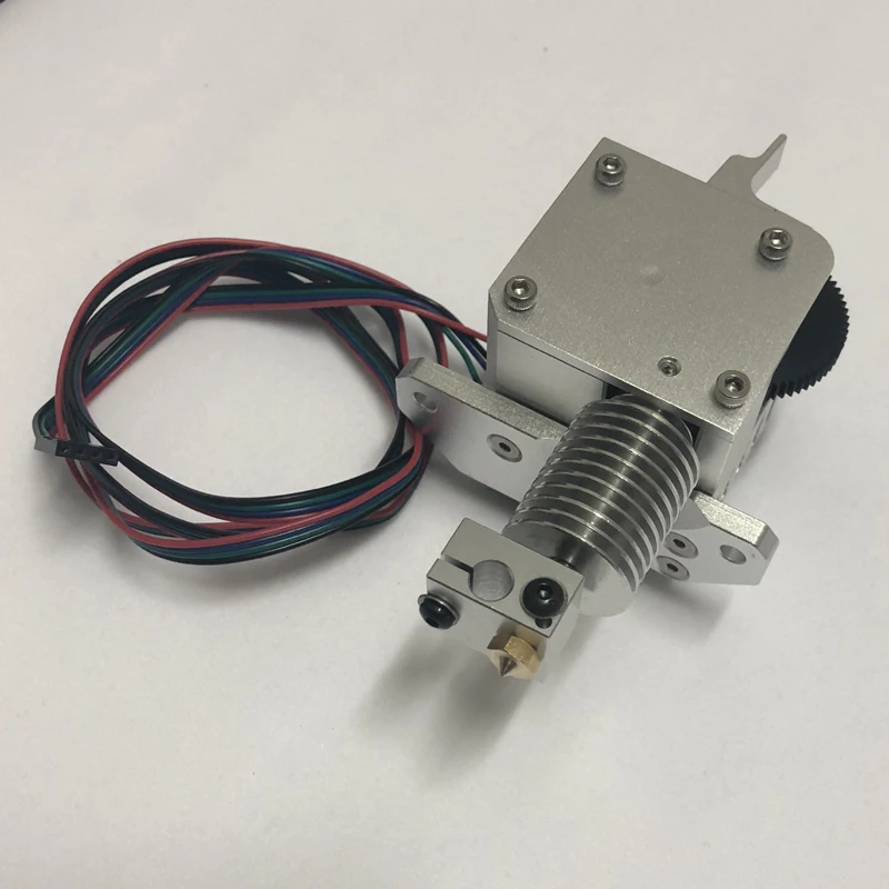 5 and 0.75 mm, respectively) and the extrusion per mm but keeping the pattern the same.
Figure 3:
Collection of structures printed with gelatine, including thick (3 mm) and thin (1 mm) single lines, slump tests and low-lying vertical structures like the step-wedge. In each case, the ink consists of a 10-20 wt% mix of gelatine, water and a small amount of carbon black pigment, for visual clarity. This highlights the common drawbacks of printing the material, including loss of detail due to flow, retraction issues and setting during the printing process.
Due to the effectively liquid state in which the ink leaves the nozzle, the resolution of a single line is limited by a combination of liquid flow on the printbed and die swelling effects. Measured line widths are regularly in the region of 1 - 2 mm, with a nozzle width range of 0.4 - 1.7 mm, and right-angled corners display a similar and more pronounced broadening effect. The data of which can be found in Fig.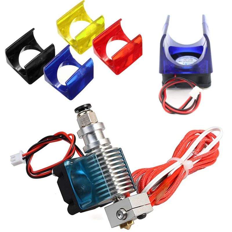 4. Additionally, due to the slowly increasing viscosity provided by the lack of temperature control, this line width appears to decrease over time, ensuring the slump test succeeds up to as many as ten layers (circular print in Fig. 4) and overhanging layers are possible for small overhangs (rectangular ramp increasing in height and overhang).
Figure 4:
(Above) Data for the measured line and corner width of a 17.5wt% aqueous gelatine mix held at 40°c and averaged over three measurements. (Below) Data for the swelling of the individual line and 90°for printed gelatine at a variety of nozzle widths. As expected, the swelling ratio decreases as the nozzle width increases.
This particular ink and hardware combination could be improved by focusing on the temperature effects across the extrusion. Setting within the reservoir and nozzle could be avoided by heating within these sections to reasonable temperatures of 40 - 50°. This could be combined with a cooling of the printbed in order to discourage flow of the ink upon leaving the nozzle.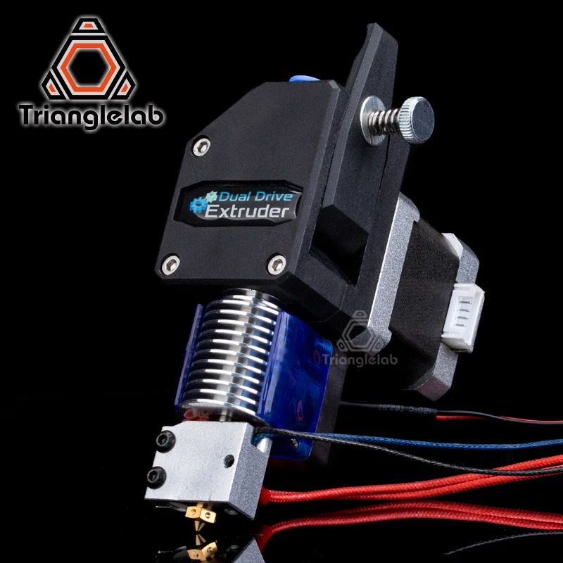 Alternatively, an ink formulation driven approach could seek to use a higher concentration of gelatin or a gelatin component with a higher Bloom, in order to encourage quicker setting on the buildplate.
The slump test for gelatine, seen in Fig. 3, produced useful data beyond the simple dimensional data. It was found that as the print was undertaken, the printed line width decreased until the ink mixture set in the nozzle and the print was no longer achievable. For a mixture heated to 40°c, measurements of the line width were taken from a continuous line print, noting the time from initial extrusion. The continuous printing, with no periods of retraction, encourages a longer suitable print window before clogging. This is shown in Fig. 5, displaying a near halving of the print width over the course of a 10 minute print.
Figure 5:
Data showing the decrease in linewidth with time, due to the setting of the gelatine ink within the reservoir and nozzle.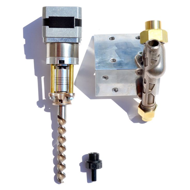 Each data point is averaged over three attempted prints. Beyond 600 seconds, the ink had set too much to be extruded.
Conical sections up to 1.5 mm were produced before the setting stalled the print, giving a height shrinkage value of HS = 0.65 and ratios of the bottom and top diameters as TSB = 1.24 and TST = 0.92 respectively. This suggests a flow after deposition on the build plate, that expands the lower diameter and decreases the upper diameter. It should be noted, however, that the upper diameter (that should be well defined due to the shape of the input 3D model) was instead hard to identify in certain places in the print due to the ink flow and so measurements were hard to take.
Finally, the step-wedge print test, also seen in Fig. 3, was produced. This is useful for highlighting the generic issues with the printing material, including the loss of detail due to material flow, retraction values being hard to control and decrease in the printed line width with time due to setting of the ink.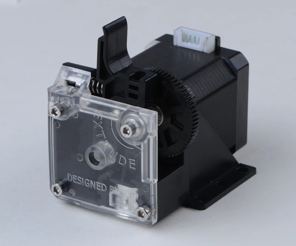
5.2 Chitosan
Chitosan is another similar material to gelatine, providing high biocompatibility with a non-toxic and inexpensive material [41]. Unlike gelatin however, it has a long gelation time and therefore is immediately a less suitable material for printing. Despite this, it provides a useful vector for probing how the movement of the ink on the printing plate after deposition.
A mixture of 1:9 of chitosan powder and household vinegar (in place of acetic acid) was produced by mixing by hand and leaving for 24 hours in a cooled enviroment. This allowed for the complete dissolution of the chitosan powder and an extrudable but viscous solution. A simple scaffold design was printed, one layer high, and the line width measurements were now monitored over time - the results shown in Fig. 6. As expected, the slower gelation times resulted in a slow dilution of the print line, increasing the measured width, and explaining the common need to alter chitosan-based inks with other additives to make them more suitable for printing [41, 42].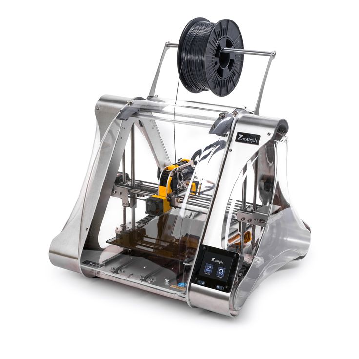
Figure 6:
Data showing the increase in linewidth with time, due to the slow gelation time of chitosan. Each data point is average over three attempts. Beyond 1000 seconds, marginal differences were seen in the line width measurements, however the ink had only partially set.
5.3 Marmite
Marmite presents a simple case for a conductive paste, in order to produce custom (and edible to some) circuitry [39]. It is a highly viscous material that exhibits shear-thinning behaviour, which increases with increasing temperature. Despite this, it has been shown to be readily printable at room temperature using a BioBot 1 extrusion printer [39]. We use this test case to explore how a functional viscous material may be extruded, without the strict temperature dependence and setting behaviour exhibited by a material such as gelatine.
Initial extrusion tests show that the highly viscous behaviour of the material means that in order for consistent extrusion to take place, the feedrate must be slowed and the delay between the stepper motor instructions and deposition from the nozzle mean that retraction is an inherent issue.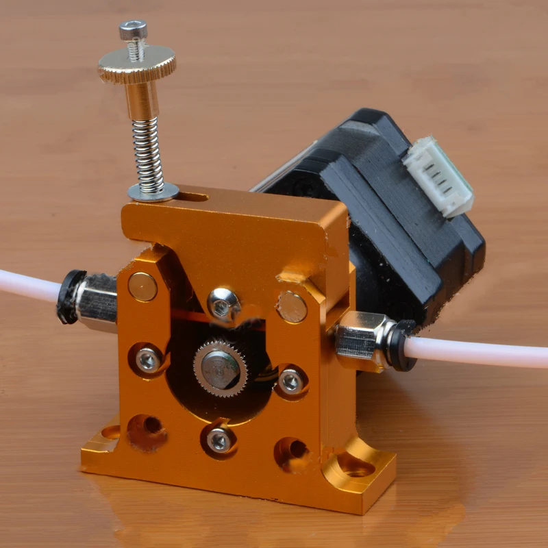 We find however that once the ink is moving under inertia, the printed single lines are of a consistently high resolution, hindered only by the presence of air introduced by placing the highly viscous material in the syringe.
As there is no setting component to the ink, we can assume that anything we print will slowly flow, regardless of structure, and so aim only to explore the range of designs that are relatively fast, on the scale of minutes. A key component of the work in Ref. [39, 53] is the production of electrically conductive channels - slower printing with larger nozzle diameters can produce thick conductive routes on a variety of substrates, as seen in Fig. 7.
Figure 7:
Using Marmite as an ink within the paste extruder system. No changes are made to the material and it is printed at room temperature, showing thin printed lines that are affected by the presence of air bubbles in the system (Left). When printed at slower speeds with larger nozzles sizes, these dislocations become less important and thick conductive lines can be printed to make similar circuitry to that in Ref. [39]
[39]
Figure 8:
Examples of the software component of the paste extrusion system. (Upper left) A CAD programme, for design of 2D and 3D objects for printing. Here we highlight TinkerCAD, a free browser based CAD programme, useful for beginners. (Upper right) Slicing software, in this case Slic3r, for producing custom ink-specific instructions per object. (Lower) Printer interface for monitoring and sending the instructions produced by the slicing software. All together this shows one possible workflow for the software component of the paste extruder setup.
6 Conclusion
We present a low-cost and easy-to-assemble platform for the extrusion and selective deposition of gels and pastes, when combined with a generic desktop 3D printer. This is designed to be easy to use and manipulate, in order to make it compatible with a wide range of printers and printing material. As such, we utilise a handful of extremely simple printing tests that can be used to produce material profiles, to help move toward repeatable and clean prints.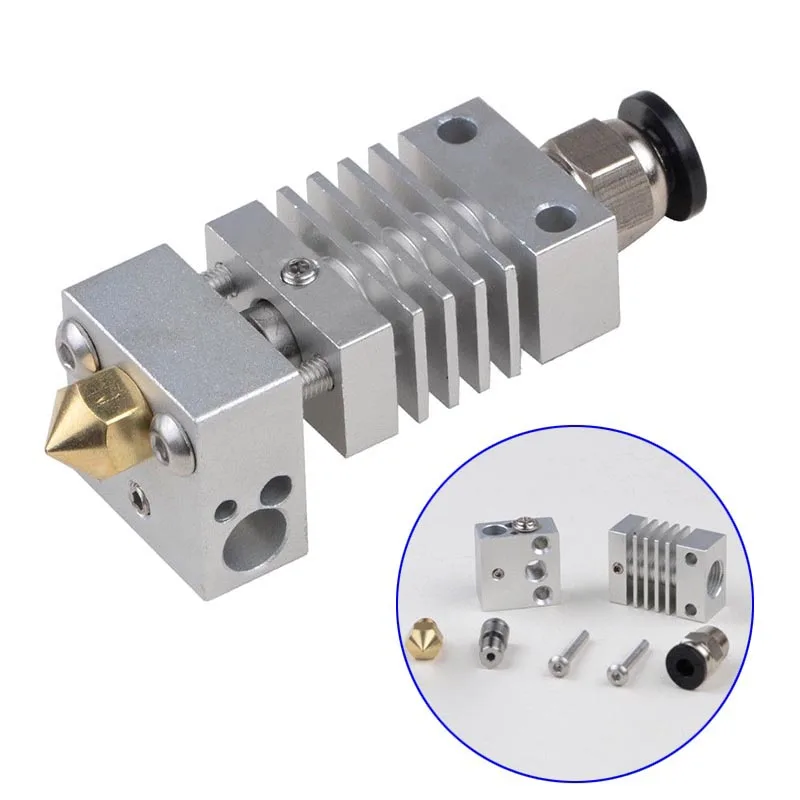 Using these, we explore a handful of material case studies, differing in viscosity and setting properties, and highlight how early testing data could be used to produce specific material/printer profiles.
Appendix A Software
The software component of the system comprises of three distinct responsibilities; a Computer Aided Design (CAD) component, a slicer and an interface with the printer. Certain aspects of these may be integrated into one software package, but it can be useful for the purposes of the workflow to have them separated. The CAD component is present to provide a work space for the design of 2D/3D objects for the printer. There are a huge range of options when choosing CAD software, each with varying focuses and degrees of complexity, but with many overlapping premises and approaches, so much of it comes down to personal preference. The slicer component is used to produce profiles that determine exactly how a desired three dimensional object will be broken into two-dimensional slices and then translated into the G-Code instructions for the print. These profiles can be tuned to be material specific, based on terms including, but not limited to:
For this, we recommend Slic3r [54] and provide a collection of material profiles that have been tested on the paste extruder setup within the Supplementary Information. These can be used as starting points for similar materials, however they may require further tuning for each particular ink formulation and printer combination.
For the interface, we use either Pronterface [55] or Octoprint [56]. Both allow for line-by-line live entry of G-Code and therefore can highlight the particular instructions and movements that may be causing failure within the print. More generally, any interface that allows for monitoring of the print, live pausing and resuming and the sending of instructions directly should be suitable.
Appendix B Standard Procedure
A general workflow for the extrusion of a generic ink mixture may look something like:
Digital Design - Production of desired STL in CAD design software (Fusion 360, Rhino, Tinkercad etc.
 ) and translation to G-Code via slicing software.
Ink Formulation - Identification of desired printing material and the routes of processing and modification required to produce a sufficient ink.
Slicing Parameters - Variation of the slicing parameters in slicing software to ensure that the interpretation of the digital model matches the limitations of the ink. This stage is the most obvious point of variation for iteratively finding a combination of software and material properties that ensure a printable ink.
Reservoir Filling - Syringe must be filled with the chosen ink recipe. For particularly viscous inks, this can cause issues with trapping air pockets that can be overcome by vacuum degassing or simply allowing time for the air bubbles to rise to the surface. Air bubbles will cause intermittent extrusion issues and variation in the pressure applied to the ink by the syringe pump.
Priming Syringe Pump - Due to the relative nature of the extruder stepper motor coordinates, it often defaults to a zero position upon a reset of the printer, no matter the actual position of the compressive wedge.
 It is theoretically possible to change these settings within the printer, however this limits the rate at which the machine can be returned to a simple thermoplastic extruder and so we choose to work around it. It is difficult to determine a set of G-Code instructions that will ‘home’ the extruder motor and we instead drive the stepper motor manually to the desired starting position, using linear move (G1) commands. For example:
 Loading Syringe Pump - Once the syringe pump and filled syringe are aligned, the syringe is loaded into the pump and secured with the cradle screw. The nozzle and the printbed are aligned by hand, typically with the same tolerance you would aim for in a standard 3D print levelling process. Extrusion commands are sent manually to the machine until the connector tubing and nozzle and filled with ink.
Build Area Test - Interaction between the syringe pump and printer dimensions are tested, including ensuring the connector tubing does not interfere with the movement of the print.
 Below is a series of generic instructions that can be used to probe this movement, the magnitudes may vary between printer types.
 Extrusion Test - To ensure there are no regions of pressure build-up and potential failure, a short extrusion test should be undertaken prior to printing. This is another chance to ensure the nozzle tip and printbed are sufficiently spaced. The code below moves to a uncommonly used space, initiating a small extrude move, and then tests the extrusion at the plate and above the plate, before retracting a little to ensure any induced flow slows down.
Running Print - Finally, the print instructions can be sent to the printer. The printer should be monitored during this phase to ensure there is no clogging or stepper motor skipping that could damage the print setup.
Appendix C Inherent Advantages & Limitations
This extruder design has some inherent advantages over commercial paste extruders and bioprinters, such as:
A low price.
 Components are either 3D printed or comprised of commonly found and cheap items. The majority of the cost arises from the original 3D printer.
Compatibility with a variety of desktop FDM 3D printers. This is due to the majority of the design being external to the printer, with only the nozzle portion being in contact the 3D printer.
The design is modular, allowing for individual components to be swapped depending on the users needs. Common variables include the syringe, nozzle and tubing dimensions and the choice of stepper motor. Additionally, this design could also incorporate a range of further external modifiers, including temperature control and optical interactions.
Can easily be converted back into a plastic 3D printer.
Wide range of material choice. Modification to both hardware and software is always an option to increase printability.
Requires little specialist knowledge. The ease of assembly and intentionally straight-forward nature of the design make this accessible to a wide variety of academic backgrounds, as well as being a useful and visually impressive tool for education and outreach.
It also has some inherent limitations, the understanding of which can help with material choice and ink formulation. These include:
Uneven extrusion due to plastic warping, present in both the body of the syringe pump and the syringe itself. This could be partially averted in the latter case through the use of a more structurally stable glass or metallic syringe.
Retraction is limited, particularly in comparison to air pressure methods. This can induce overextrusion and stringing and make it difficult to fabricate objects where the print cannot be completed in a single continuous line.
The reservoir size is large but still limited. Whilst this is suitable for low-lying prints of tens of layers, it cannot extend to the furthest reaches of the possible print dimensions. This is due to the design of the syringe pump and so could be side-stepped through modification of this stage.
Connector tubing increases the chance of stepper motor skipping with increasing length.
 This can be avoided by minimising the length of the connector tubing and allow ample time for the system to settle between extrusion commands when initially filling the tubing.
There is no failsafe implemented. As such, if an ink formulation is less reliable (or even unprintable), the design causes stress on the body of the syringe pump and the stepper motor by skipping steps. This is particularly true during larger prints, in which the printer orchestrates many instructions in succession and can cause a pressure build up faster than the material can be effectively extruded. In these case, a reduced feedrate can result in more even extrusion and less chance of stepper motor skipping.
References
- [1].↵
Giordano, R. A., Wu, B. M., Borland, S. W., Cima, L. G., Sachs, E. M., & Cima, M. J. (1997). Mechanical properties of dense polylactic acid structures fabricated by three dimensional printing. Journal of Biomaterials Science, Polymer Edition, 8(1), 63–75.

- [2].↵
Rodríguez, J. F., Thomas, J. P., & Renaud, J. E. (2003). Mechanical behavior of acrylonitrile butadiene styrene fused deposition materials modeling. Rapid Prototyping Journal.
- [3].↵
Murphy, S. V., & Atala, A. (2014). 3D bioprinting of tissues and organs. Nature biotechnology, 32(8), 773–785.
- [4].↵
Chia, H. N., & Wu, B. M. (2015). Recent advances in 3D printing of biomaterials. Journal of biological engineering, 9(1), 1–14.
- [5].↵
Jiang, T., Munguia-Lopez, J. G., Flores-Torres, S., Kort-Mascort, J., & Kinsella, J. M. (2019). Extrusion bioprinting of soft materials: An emerging technique for biological model fabrication. Applied Physics Reviews, 6(1), 011310.
- [6].↵
Kotz, F., Arnold, K., Bauer, W., Schild, D., Keller, N., Sachsenheimer, K., Nargang, T.M., Richter, C.
 , Helmer, D., & Rapp, B. E. (2017). Three-dimensional printing of transparent fused silica glass. Nature, 544(7650), 337–339.
 - [7].↵
Klein, S., Simske, S., Adams, G., Parraman, C., Walters, P., Huson, D., & Hoskins, S. (2012, January). 3D printing of transparent glass. In NIP Digital Fabrication Conference (Vol. 2012, No. 2, pp. 336–337). Society for Imaging Science and Technology.
- [8].↵
Wang, X., Jiang, M., Zhou, Z., Gou, J., & Hui, D. (2017). 3D printing of polymer matrix composites: A review and prospective. Composites Part B: Engineering, 110, 442–458.
- [9].↵
Zarek, M., Layani, M., Cooperstein, I., Sachyani, E., Cohn, D., & Magdassi, S. (2016). 3D printing of shape memory polymers for flexible electronic devices. Advanced Materials, 28(22), 4449–4454.
- [10].↵
Buchanan, C., & Gardner, L. (2019).
 Metal 3D printing in construction: A review of methods, research, applications, opportunities and challenges. Engineering Structures, 180, 332–348.
 - [11].↵
Gibson, M. A., Mykulowycz, N. M., Shim, J., Fontana, R., Schmitt, P., Roberts, A., Ketkaew, J., Shao, L., Chen, W., Bordeenithikasem, P., & Myerberg, J. S. (2018). 3D printing metals like thermoplastics: Fused filament fabrication of metallic glasses. Materials Today, 21(7), 697–702.
- [12].↵
Buswell, R. A., De Silva, W. L., Jones, S. Z., & Dirrenberger, J. (2018). 3D printing using concrete extrusion: A roadmap for research. Cement and Concrete Research, 112, 37–49.
- [13].↵
Zhang, Y., Zhang, Y., She, W., Yang, L., Liu, G., & Yang, Y. (2019). Rheological and harden properties of the high-thixotropy 3D printing concrete. Construction and Building Materials, 201, 278–285.
- [14].
 ↵
↵Liu, Z., Zhang, M., Bhandari, B., & Wang, Y. (2017). 3D printing: Printing precision and application in food sector. Trends in Food Science Technology, 69, 83–94.
- [15].↵
Sun, J., Zhou, W., Huang, D., Fuh, J. Y., & Hong, G. S. (2015). An overview of 3D printing technologies for food fabrication. Food and bioprocess technology, 8(8), 1605–1615.
- [16].↵
Faes, M., Valkenaers, H., Vogeler, F., Vleugels, J., & Ferraris, E. (2015). Extrusion-based 3D printing of ceramic components. Procedia Cirp, 28, 76–81.
- [17].↵
Minas, C., Carnelli, D., Tervoort, E., & Studart, A. R. (2016). 3D printing of emulsions and foams into hierarchical porous ceramics. Advanced Materials, 28(45), 9993–9999.
- [18].↵
Mackay, M. E. (2018). The importance of rheological behavior in the additive manufacturing technique material extrusion.
 Journal of Rheology, 62(6), 1549–1561.
 - [19].↵
Lewis, J. A. (2006). Direct ink writing of 3D functional materials. Advanced Functional Materials, 16(17), 2193–2204.
- [20].↵
Roehm, K. D., Madihally, S. V. (2017). Bioprinted chitosan-gelatin ther-mosensitive hydrogels using an inexpensive 3D printer. Biofabrication, 10(1), 015002.
- [21].↵
Lee, J., Kim, K. E., Bang, S., Noh, I., & Lee, C. (2017). A desktop multimaterial 3D bio-printing system with open-source hardware and software. International journal of precision engineering and manufacturing, 18(4), 605–612.
- [22].↵
Amza, C. G., Zapciu, A., & Popescu, D. (2017). Paste extruder—hardware add-on for desktop 3D printers. Technologies, 5(3), 50.
- [23].↵
Pusch, K., Hinton, T. J., & Feinberg, A. W. (2018). Large volume syringe pump extruder for desktop 3D printers.
 HardwareX, 3, 49–61.
 - [24].↵
An, J., Teoh, J. E. M., Suntornnond, R., Chua, C. K. (2015). Design and 3D printing of scaffolds and tissues. Engineering, 1(2), 261–268.
- [25].↵
Banović, L., & Vihar, B. (2018). Development of an extruder for open source 3D bioprinting. Journal of Open Hardware, 2(1).
- [26].↵
Fitzsimmons, R. E., Aquilino, M. S., Quigley, J., Chebotarev, O., Tarlan, F., & Simmons, C. A. (2018). Generating vascular channels within hydrogel constructs using an economical open-source 3D bioprinter and thermoreversible gels. Bioprinting, 9, 7–18.
- [27].↵
Bessler, N., Ogiermann, D., Buchholz, M. B., Santel, A., Heidenreich, J., Ahmmed, R., Zaehres, H. & Brand-Saberi, B. (2019). Nydus One Syringe Extruder (NOSE): A Prusa i3 3D printer conversion for bioprinting applications utilizing the FRESH-method.
 HardwareX, 6, e00069.
 - [28].↵
Alruwaili, M., Lopez, J. A., McCarthy, K., Reynaud, E. G., Rodriguez, B. J. (2019). Liquid-phase 3D bioprinting of gelatin alginate hydrogels: influence of printing parameters on hydrogel line width and layer height. Bio-Design and Manufacturing, 2(3), 172–180.
- [29].↵
Klar, V., Pearce, J. M., Kärki, P., & Kuosmanen, P. (2019). Ystruder: Open source multifunction extruder with sensing and monitoring capabilities. HardwareX, 6, e00080.
- [30].↵
Sanz-Garcia, A., Sodupe-Ortega, E., Shimizu, T., Escobedo-Lucea, C. (2020). A versatile open-source printhead for low-cost 3D microextrusionbased bioprinting. Polymers, 12(10), 2346.
- [31].↵
Booeshaghi, A. S., da Veiga Beltrame, E., Bannon, D., Gehring, J., & Pachter, L. (2019). Principles of open source bioinstrumentation applied to the poseidon syringe pump system.
 Scientific reports, 9(1), 1–8.
 - [32].↵
Wijnen, B., Hunt, E. J., Anzalone, G. C., & Pearce, J. M. (2014). Opensource syringe pump library. PloS one, 9(9), e107216.
- [33].↵
Garcia, V. E., Liu, J., DeRisi, J. L. (2018). Low-cost touchscreen driven programmable dual syringe pump for life science applications. HardwareX, 4, e00027.
- [34].↵
Neumaier, J. M., Madani, A., Klein, T., Ziegler, T. (2019). Low-budget 3D-printed equipment for continuous flow reactions. Beilstein journal of organic chemistry, 15(1), 558–566.
- [35].↵
Händle, F. (Ed.). (2007). Extrusion in ceramics. Springer Science Business Media.
- [36].↵
Guilherme, P., Ribeiro, M. J., & Labrincha, J. A. (2009). Behaviour of different industrial ceramic pastes in extrusion process. Advances in Applied Ceramics, 108(6), 347–351.
- [37].↵
Leech, D. J., Lightfoot, S., & Jorgensen, T. (2020). Geometric Pressure Minimisation of a Theoretical Die for Ceramic Extrusion. arXiv preprint arXiv:2007.12588.
- [38].
Lanaro, M., Forrestal, D. P., Scheurer, S., Slinger, D. J., Liao, S., Powell, S. K., & Woodruff, M. A. (2017). 3D printing complex chocolate objects: Platform design, optimization and evaluation. Journal of Food Engineering, 215, 13–22.
- [39].↵
Hamilton, C. A., Alici, G., & in het Panhuis, M. (2018). 3D printing Vegemite and Marmite: Redefining “breadboards”. Journal of food engineering, 220, 83–88.
- [40].
Liu, Z., Zhang, M., Bhandari, B., & Yang, C. (2018). Impact of rheological properties of mashed potatoes on 3D printing. Journal of Food Engineering, 220, 76–82.
- [41].↵
Elviri, L., Foresti, R., Bergonzi, C.
 , Zimetti, F., Marchi, C., Bianchera, A., Bernini, F., Silvestri, M. & Bettini, R. (2017). Highly defined 3D printed chitosan scaffolds featuring improved cell growth. Biomedical Materials, 12(4), 045009.
 - [42].↵
Demirtaş, T. T., Irmak, G., & Gümüşderelioğlu, M. (2017). A bioprintable form of chitosan hydrogel for bone tissue engineering. Biofabrication, 9(3), 035003.
- [43].
Jia, J., Richards, D. J., Pollard, S., Tan, Y., Rodriguez, J., Visconti, R. P., Trusk, T.C., Yost, M.J., Yao, H., Markwald, R.R. & Mei, Y. (2014). Engineering alginate as bioink for bioprinting. Acta biomaterialia, 10(10), 4323–4331.
- [44].
Revelo, C. F., Colorado, H. A. (2018). 3D printing of kaolinite clay ceramics using the Direct Ink Writing (DIW) technique. Ceramics International, 44(5), 5673–5682.
- [45].
Zein, I., Hutmacher, D.
 W., Tan, K. C., Teoh, S. H. (2002). Fused deposition modeling of novel scaffold architectures for tissue engineering applications. Biomaterials, 23(4), 1169–1185.
 - [46].
Le, T. T., Austin, S. A., Lim, S., Buswell, R. A., Gibb, A. G., Thorpe, T. (2012). Mix design and fresh properties for high-performance printing concrete. Materials and structures, 45(8), 1221–1232.
- [47].↵
Ferraris, C. F., & de Larrard, F. (1998). Modified slump test to measure rheological parameters of fresh concrete. Cement, Concrete and Aggregates, 20(2), 241–247.
- [48].↵
Montero, P., Fernández-Diaz, M. D., Gómez-Guillén, M. C. (2002). Characterization of gelatin gels induced by high pressure. Food Hydrocolloids, 16(3), 197–205.
- [49].↵
Gekko, K., Fukamizu, M. (1991). Effect of pressure on the sol-gel transition of gelatin. International journal of biological macromolecules, 13(5), 295–300.
- [50].↵
Yue, K., Trujillo-de Santiago, G., Alvarez, M. M., Tamayol, A., Annabi, N., & Khademhosseini, A. (2015). Synthesis, properties, and biomedical applications of gelatin methacryloyl (GelMA) hydrogels. Biomaterials, 73, 254–271.
- [51].↵
Di Giuseppe, M., Law, N., Webb, B., Macrae, R. A., Liew, L. J., Sercombe, T. B., Dilley, R.J. & Doyle, B. J. (2018). Mechanical behaviour of alginate-gelatin hydrogels for 3D bioprinting. Journal of the mechanical behavior of biomedical materials, 79, 150–157.
- [52].↵
Hellio, D., Djabourov, M. (2006, July). Physically and chemically crosslinked gelatin gels. In Macromolecular Symposia (Vol. 241, No. 1, pp. 23–27). Weinheim: WILEY-VCH Verlag.
- [53].↵
Keller, A., Pham, J., Warren, H., & in het Panhuis, M. (2017). Conducting hydrogels for edible electrodes. Journal of Materials Chemistry B, 5(27), 5318–5328.
- [54].↵
https://slic3r.org/ (Accessed 11/08/20).
- [55].↵
https://www.pronterface.com/ (Accessed 11/08/20).
- [56].↵
https://octoprint.org/ (Accessed 11/08/20).
Back to top
Type extruders: advantages and shortcomings. 3Dplast
In the FDM technology, and we are talking about it ourselves, the extruder creates an object ball by ball, seeing the other material - the filament - through the nozzle. It is made up of such attachments from two parts: the body of the extruder and the heating part (there is a hot end).
The extruder body itself can be either plastic or metal. Here it’s already a good idea to pay attention to the quality of the vikonnanny, even if the skin detail is important - a slightly attached gear can lead to an incorrect supply of plastic and, as a last resort, to pardons to a friend.
There are three main types of extruders:
- Straight type.
- Indirect type - Bowden.
- For others with pasty materials.
The right choice of extruder should be in the first place depending on the design features of your printer, but all types may have their advantages and disadvantages. Even more often, extruders, like 3D printers, are delivered in kits for self-assembly. It is important to be aware of the types of extruders and materials for their preparation - you should not have mercy on choosing the extruder itself.
Before speech, the quality of materials, from such preparations, the extruder itself and its storage parts, are also of great importance. The higher the brightness, the more accurate the rubbing, the less problems are caused when working with different types of stained glass material. In this type of varto, all the same, swipe your vibir on the details, and not on the overwork, the shards to wind a splinter of millimeters in the retail can lead either to the slipping of the thread, or to the її zalutuvannya.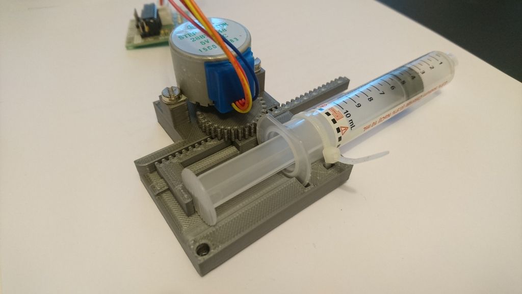 І tse unambiguously signify on the quality of the inflicted virobiv.
Well, I would like to note that you should take into account the diameter of the extruder nozzle - and use it with these materials, with which you plan to work. The stench is shamelessly guilty.
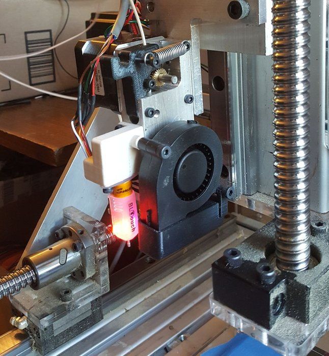
Straight type extruder
This printer has a feeding mechanism located directly on the rough carriage. Such a presentation allows you to make a quick and precise delivery of plastic, minimally. Tse allows you to change the kidnapping in front of a friend. For the direct type of extruder, it is also possible to vicorate gnuchka materials. Greater diversity in the choice of materials ensures a greater choice of objects, which can be developed. Until then, such a system has fewer problems when replacing stained glass material.
In addition, the main shortcomings are the size and dimensions of the extruder. The cream is more foldable design of the entire annex, it requires more thin firmware. Great vag - tse great inertness. Such a carriage cannot be mittted in the event of a pardon, and the shoe is liable to damage during programming, especially when creating new models.
Bowden
In this option, the extruder is connected to another mechanism, the filament is fed through a pipe to the hot end. Such a feed allows you to lighten the weight of the carriage for the rahunok, the weight of the engine on the frame.
The speed of a friend is allowed to be more, but the need for work with great powers is greater than the effort of a dvigun. Until then, ce mezhuє work with soft materials. The change in the supply of a bar for a friend is also increased. That change of material becomes more collapsible.
Two types of extruders can be used with two types of drives - straight and with gears. The first type sends material directly to the hotend. The standard thread diameter for extruders of this type is 1.75 mm. The stench is chomping on the filament and shoving yoga into the nozzle. Sound victorious when working with a material of a larger diameter - 3 mm in diameter. Tse bezpechuє great force in the work. The design of the direct drive is simpler and victorious in a larger number of models.
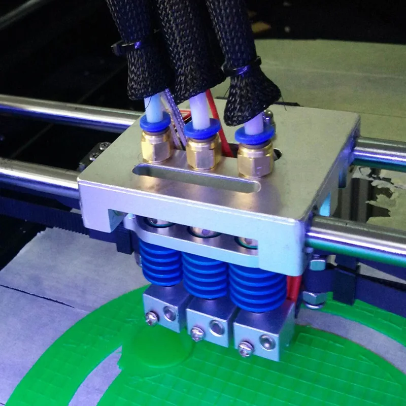
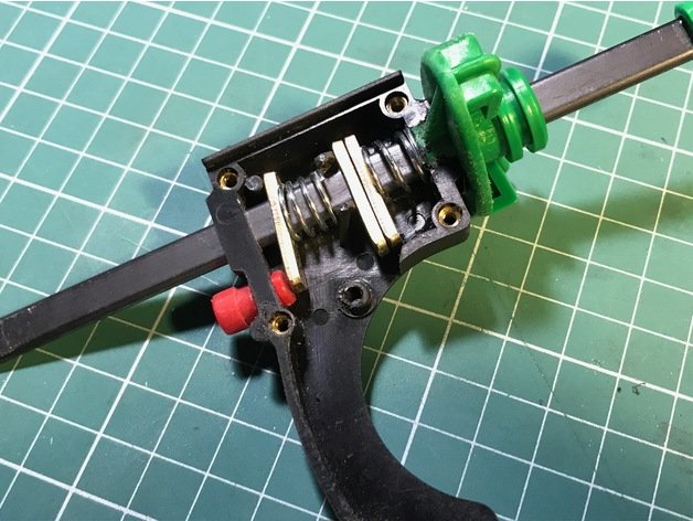
For other pasty materials Vyazke mill vyhіdny material does not allow vikoristovuvat neither bowden nor direct type. Here the extruder is more guessing a great syringe, similar to those, like vicorist in confectionery.
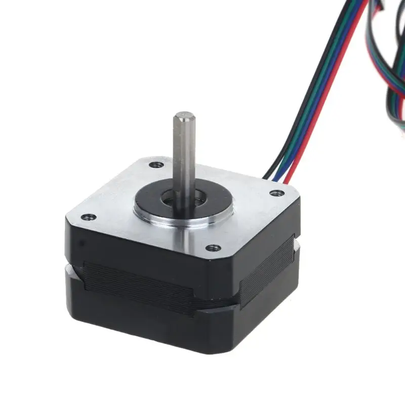
 Vіn to be driven in pneumatics or by a stepper motor. The same principle is victorious in the currently popular 3D pens, as the simplest, but at the same time it can be effective. Before speech, this type is also considered the safest.
Nozzle number classification In the last hour for the creation of more folding models, extruders with two nozzles appeared. Variants of the order and the sequence of victories in the beginning are collected about a dozen.
Main design features:
- possibility to use different colors, both in series and in parallel;
- other different materials - important when folding folding arms with the need for another soluble lining;
- high quality to each other.
Nedoliki – foldable design and high versatility.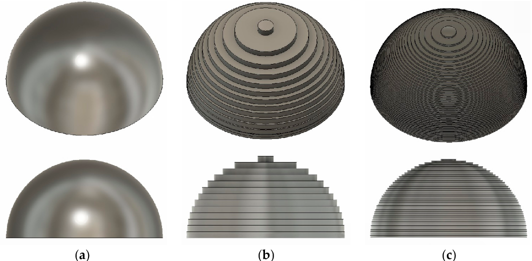 Є sensation vikoristovuvaty only if necessary in the press, effectively folding rich-component models and prototypes. With usima іnshimi zavdannya vіdminno cope and extruders with one nozzle.
Visnovki
The extruder is at the heart of the 3D printer, so it can be buti- lently primed, out of the box. Obov'yazkovo insure this type when writing programs for models - the least pardon in terms of inertness, or the supply temperature can be brought to the appearance of technological shortcomings in the overcharged pipes.
-
3D friend of great objects It turns out that you can't abuse anyone, what's bigger than a printer? With the help of these methods, you can develop them independently from your 3D printer.
3D friend of great objects
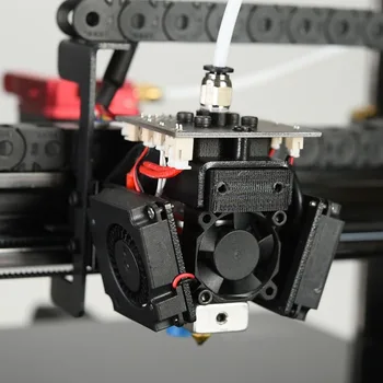
3D printer print head
3D printer print head is called an extruder (from English extrude - extrude). The name reflects the principle of operation: the print head extrudes the thermoplastic through a special nozzle. Drawing an analogy, glue guns common in everyday life, syringes with sealant, tubes of toothpaste, and finally, operate in the same way.
As a rule, filament (filamentary) thermoplastics such as ABS or PLA are used for 3D printers. What to choose for printing - see the article: Choosing plastic for printing on a 3D printer.
However, sometimes more exotic plastics are used, for example, you can print with nylon on a 3D printer, in fact, cheap trimming line is used.
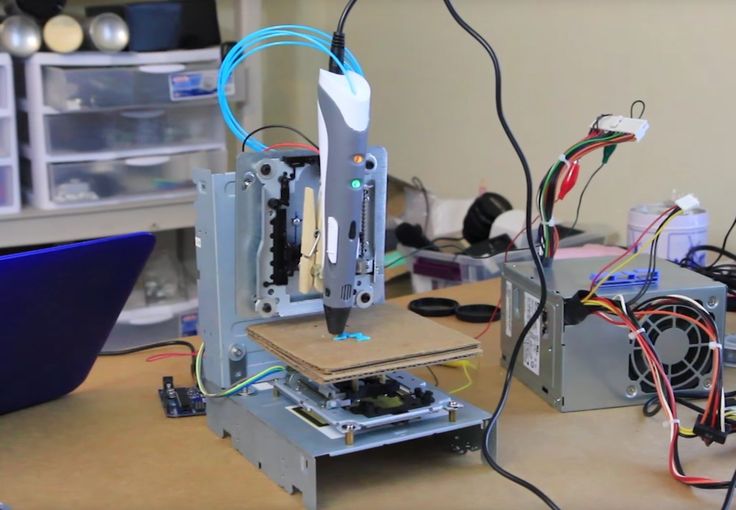
Despite the variety of 3D printers, their printheads are made on the same principle and do not differ much from each other. For example, a small Myrwell 3D pen is actually a full-fledged extruder enclosed in a body that is comfortable to hold in your hand.
Extruders in general and direct feed extruder in particular can be divided into two main blocks:
- cold-end (literally "cold end") - a mechanism that provides filament supply;
- hot-end (literally "hot end") - nozzle with heater.
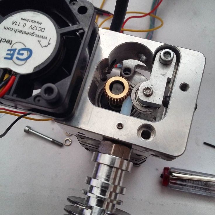
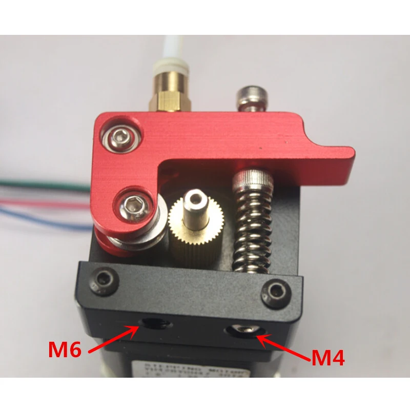
Cold-end , in turn, consists of a gear driven by an electric motor (direct or gear connection) and a clamping mechanism. A rotating gear removes the filament from the spool and passes it into the heater, where the thermoplastic changes its state of aggregation from solid to viscous under the influence of high temperatures, which allows it to be extruded through a nozzle and given the desired shape.
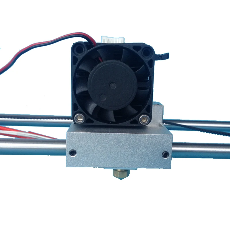
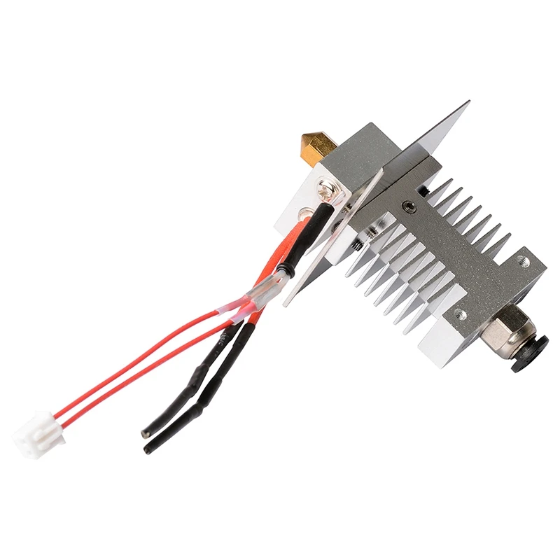
Hot-end is made of aluminum or brass (due to the high thermal conductivity of these metals). The heater consists of a spiral (nichrome wire) and a pair of resistors, as well as a thermocouple for temperature control.
During operation, the hot-end heats up because the melting temperature of the plastic is high enough. At the same time, the rest of the system must remain cold throughout the entire operation cycle. To prevent premature melting of the thermoplastic, there is a heat insulating insert between the "hot" and "cold" ends.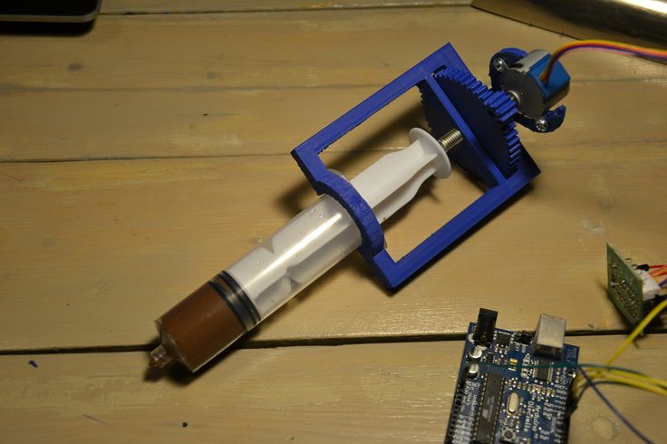 Moreover, the extruder is sometimes equipped with an additional heatsink with a fan.
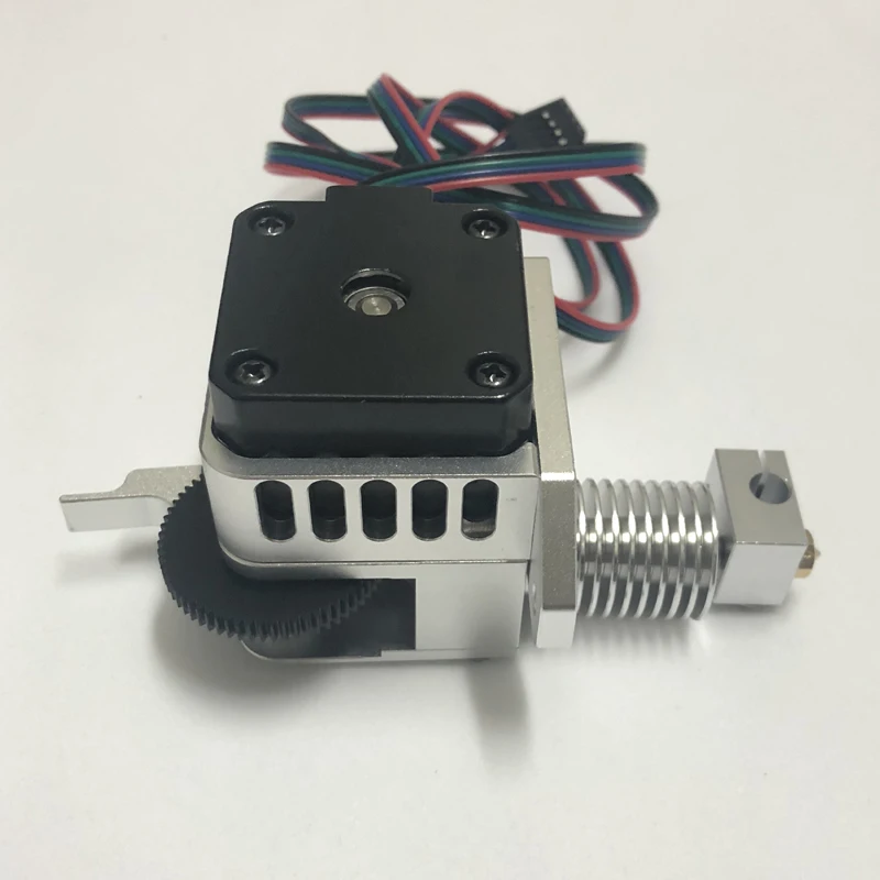
Another type of printhead is bowden extruder extruder (English Bowden extruder ). They differ from direct filament extruders in that the hot-end and cold-end components are spatially separated: the heater and nozzle are located on the print head, and the feeder is located on the frame of the 3D printer.
The filament is fed through a long Teflon tube, however, if there is no Teflon, then an ordinary plastic one is also used, but then a more powerful engine must be installed, as there is frictional resistance in the supply tube.
The tube is needed so that the plastic thread does not bend and is fed into the hot end with decent pressure and speed.
Here is a small video review of the Bowden extruder - the video shows a modified version for a delta 3D printer.
The advantage of such a conceptual solution is the reduction in the size and weight of the print head, the minus is that the supply of thermoplastic to the nozzle becomes not as reliable as in direct feed extruders.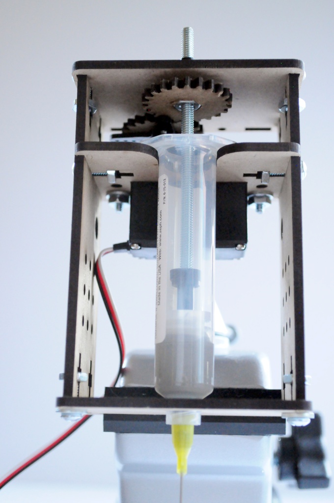
Important details to consider when choosing a head for your homemade 3D printer.
Material . Extruders can be equipped with either 3D printed or cast components. It should be borne in mind that the cast parts are stronger, which is especially important if we are not talking about the case, but about those parts of the system that are constantly under stress. Printed components are cheaper, but their strength is an order of magnitude lower than that of cast ones. On the other hand, you can always print spare parts for the 3D printer extruder yourself.
Filament supply . The quality of the feed mechanism determines the continuous supply of filament to the heater, which means it ensures uninterrupted printing. The fact is that the plastic for printing on the way to the nozzle can get confused. If the electric motor has sufficient power, then even the presence of small entanglements will not affect the operation of the entire system.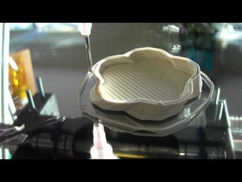
Feed roller type .
Another problem that may occur is thread slippage due to poor grip on the feed roller. This is true when printing with nylon filament on 3D printers designed to use ABS or PLA thermoplastics, since the feed wheels are made with smooth teeth here. In such cases, it makes sense to use a roller with sharp teeth.
Extruder nozzle size . Printheads are equipped with nozzles with a diameter of 0.4 - 0.5 mm, or 0.2 - 0.3 mm. It all depends on the context in which you plan to use the 3D printer. If the detail of the drawn objects and the increased accuracy of their positioning are important, nozzles of smaller diameters should be chosen. Here it should be borne in mind that the smaller the size of the nozzle, the greater the likelihood of clogging, and the more powerful the electric motor is needed to extrude the thermoplastic. In other cases, extruders with a standard nozzle size of 0.5 mm will be the best option.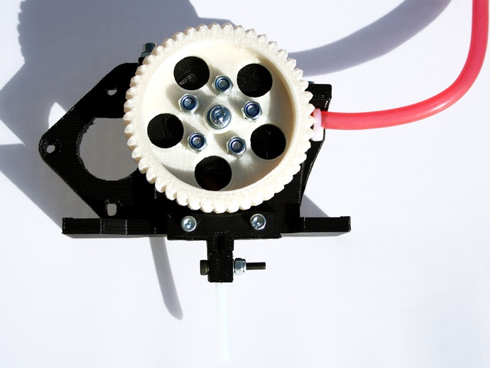
Currently, there are several models of 3D printers with two and three extruders (MakerBot Replicator Dial, 2X).
The dual extruder printers are useful for creating support structures and printing two-color objects because they can use two types of plastic. One of them can be dissolved in ordinary water and used to print support parts, and the second extruder is filled with already working PLA or ABS thread.
The disadvantage of dual-extruder printers is that both extruders are attached to the same printhead, and therefore simultaneous printing is inferior: the printer has to use the extruders separately, as needed.
However, there is also a method of simultaneous printing - "Ditto printing". In this case, the extruders work in parallel and create copies of the same object. There are also some downsides here. The technology has a very limited use, since it produces only small one-color objects, or large two-color objects with a repeating pattern.