
Moog 3d printing
Digital Manufacturing at Moog Enhances Propellant Management on Spacecraft
Our customizable, 3D printed Rolling Metal Diaphragm[1] (RMD) will reduce launch mass and optimize fuel delivery for enhanced on-orbit performance.
Key Takeaways:
- RMD is a chemical expulsion device and tank for on/off orbit propellant delivery
- Plug & play monolithic RMD reduces lead times without compromising performance
- 3D printed RMD offers vast scalability and design customization
Miniaturization of technology, components, and sub-systems is a reality for nearly all markets and industries; for space, this is critical to reduce launch costs and increase on-orbit efficiency. Laser Powder Bed Fusion (LPBF) is an additive and digital manufacturing technology that has allowed Moog to re-invigorate a heritage product: The Rolling Metal Diaphragm (RMD). The RMD is a storage tank and high-performance expulsion device, primarily for chemical propellants.
Advanced manufacturing, additive technologies, and Industry 4.0 digital supply chains are evolving and enabling producers to minimize size and mass of launch vehicles and payloads, while simultaneously mitigating historically long lead times. Engineers at Moog are leveraging additive manufacturing and trusted digital logistics solutions to reimagine green propellant combustion engines and other essential components for small satellites (smallsats), vehicles typically 500 kg or less.
When rapid and agile on or off-orbit maneuvers are required in space, chemical propulsion has always been the go-to solution. Chemical propulsion continues to present a product growth opportunity because of the rising demand for green propellant. Without compromising performance, 3D printing RMDs frees up significant working capital by reducing production costs and lead time.
The RMD is 3D printed from lightweight titanium powder into a monolithic component that is both customizable and multifunctional. No additional welding is required to assemble the flexible diaphragm; instead, it is printed integral to the shell of the tank.
Why Titanium? Titanium is compatible with and recommended for a variety of propellants, such as hydrazine, as well as ammonium dinitramide (ADN) and hydroxylammonium nitrate (HAN)-based propellants, which are effective solutions for green propellant-based missions.
To date, Moog engineers have produced and tested two different sized RMDs to explore design scalability. Both are intended to be customizable and distributed throughout any size smallsat vehicle, whether one or more RMD is needed. The additive production process allows RMDs to take on unique shapes, consistent with the vehicle layout to hold the pressurant. An example of some customization, which has been explored thus far, is the addition and relocation of connection ports on the smaller RMD to accommodate additional thrusters and more convenient fill ports.
The larger tank is nearly 10 inches in diameter, with more than a 1 U. S. gallon capacity. After seeing a sneak peek of it, some customers remarked, “This is a game changer. Cannot wait to review the characterization data.”
General dimensions and specifications are described in the table below:
Operationally, the RMD provides on demand, no-slosh metered fluid expulsion via a small, flight-proven Moog valve, without other transient dynamic response. The flexible, zero permeability diaphragm is controlled by a pressure differential, with nominal pressures up to 375 psi (~28.9 bar). While presently Moog is using 375 psi as a design metric, the pressure capability can be increased by using generative analysis tools to strengthen (not thicken) the structure strategically. Other geometric modifications can be utilized to tune pressure tolerance as desired.
Moog can supply the RMD either to be filled at the launch site or prefilled with propellant and shipped unpressurized. Commercial ground transportation companies have been licensed to carry the sizes of tanks Moog has developed.
Moog is changing the fundamental aspects of space access by enabling sustainable, cost-effective, high performance products for smallsats (ESPA class, cubesats, picosats etc.). Additive manufacturing allows the company to consolidate multi part assemblies into one monolithic RMD expulsion device while also providing custom sizes and features per-vehicle and/or per-mission needs. The RMD, as well as other products in development at Moog, are intended for a wide array of mission needs at attractive price points with drastically reduced lead times. The high-performance capabilities of the RMD make it particularly desirable for defense and critical communications where spacecraft quiescence and predictable center of gravity control is required.
1 Patent Pending
This blog consists of general capabilities information that is not defined as controlled technical data under ITAR Part 120.10 or EAR Part 772.
If you are interested in learning more about this product, please feel free to reach out to:
Jason Jones
jjones8@moog. com
com
716-334-9162
Vince Ferrante
[email protected]
650-960-4240
Additive Industry Standards
Manufacturing parts with additive (3D printing) equipment at production rate and scale will require the acceptance of industry standards for raw materials, processing, and qualification. This prerequisite will vary by industry and application, but in every case where an additive solution is adopted for production, designers and engineers will require standards that can be referenced and against which end-use articles can be verified.
We’ll consider here five different organizations that are at work in the development of industry standards, look at Moog’s involvement with these groups, and explain how these may apply to parts that you are considering for additive manufacturing.
Moog has been heavily involved in the development of these standards for a number of years, giving the company a leg up on complying with them and being able to reference them confidently on drawings and other required documents.
1. NASA Marshall – NASA’s Marshall Space Flight Center has released two documents. The first, MSFC-STD-3716 (“Standard for Additively Manufactured Spaceflight Hardware by Laser Powder Bed Fusion in Metals”) deals with controls for specific pieces of spaceflight hardware. The second, MSFC-SPEC-3717 (“Specification for Control and Qualification of Laser Powder Bed Fusion Metallurgical Processes”) pertains to control of the laser powder bed fusion additive manufacturing (LPBF-AM) process. Moog has written compliance matrices to both specifications.
2. AMS 7003 – This is a standard crafted by the Society of Automotive Engineers (SAE) for its Aerospace Material Specifications database. The purpose of the specification is to standardize the production of aerospace parts via the laser powder bed fusion (LPBF) process. As with the NASA Marshall specs, Moog has produced a compliance matrix for AMS 7003. While the Additive Manufacturing Center in Plant 11 has yet to produce a part governed by this standard, it has quoted projects whose drawings call for compliance to it. Moog collaborated with SAE in the initial drafting and revision of the specification through SAE’s Industry Technology Consortium (SAE ITC), a neutral body that gathers industry input at a pre-competitive stage to set standards industry-wide. In addition to helping draft specifications, Moog has shared data from tensile and fatigue testing of Ti64 coupons with SAE.
3. ASTM International - The organization, formerly known as American Society for Testing and Materials, is developing its own set of standards for additive manufacturing. These cover design, manufacturing, terminology, and testing methods. Among the better known of its standards is F2924-14 for the manufacture of Ti64 additive parts. Moog has reviewed a number of ASTM specifications for compliance. One key customer has called out F2924-14 on a recent RFQ.
4. AWS – The American Welding Society is also engaged in the development of AM standards and Moog is currently writing a compliance matrix to its D20. 1/D20.1M:2019 (“Standard for Fabrication of Metal Components using Additive Manufacturing.”)
5. MMPDS – the Metallic Materials Properties Development and Standardization Handbook provides a guide to material properties and design allowable values for a vast array of alloys. At present, MMPDS is working to create a new volume of its handbook series that will cover additive manufacturing. The working group tasked with writing the volume includes three subcommittees: data generation and applications; materials and machines; and certification and qualification. The last subcommittee is co-chaired by Moog’s own Dr. Paul Guerrier, the director of the Additive Technology Center in Plant 11. Because of its high-level of involvement in the MMPDS effort, Moog has a deep understanding of what flight qualification of AM parts will entail and what data will need to be generated. Moog is necessarily in regular communication with regulators (from FAA et al).
The flurry of activity in standards development reflects a growing interest in using additive manufacturing for novel solutions to engineering problems in end-use components.![]() AM will continue to play a role in prototyping though production parts will be increasingly manufactured. Engineers and designers will place their confidence in additive parts to the extent that they see their fabrication being governed by standards. These standards are being developed to a considerable degree with input from Moog. The company has been an early and leading adopter of the technology and its involvement with the generation of standards means that it has an edge in the development of additive parts for end-use production across the markets in which it competes. To learn more about the status of compliance to the standards above, please reach out to us.
AM will continue to play a role in prototyping though production parts will be increasingly manufactured. Engineers and designers will place their confidence in additive parts to the extent that they see their fabrication being governed by standards. These standards are being developed to a considerable degree with input from Moog. The company has been an early and leading adopter of the technology and its involvement with the generation of standards means that it has an edge in the development of additive parts for end-use production across the markets in which it competes. To learn more about the status of compliance to the standards above, please reach out to us.
BATTLE MUG STL File・3D Printing Idea for Download・Cults
Phone stand
1.51 €
BATTL MUG FOX
4.54 €
Super mario 3D
Free
Chrome shifter
Free
Squid tentacle mug
Free
Best 3D printer files in Game category
caddy token gun - pistol - token gun
3. 13 €
13 €
Atak Helikopteri (Attack Helicopter)
4 €
Thwomp (Super mario bros)
6.28 €
Desert buggy
1.51 €
Square medieval dice tower
5.99 €
Comura Articulatum
Free
Bestsellers in the Game category
Good flexi dragon
1.77 €
Heavily armored warriors Catafrac - set of limbs
1,85 €
Snake and rattlesnake
3.79 €
Flying unicorn
1. 77 €
77 €
Beaky Boyz Builder: PF_MK-Six
11.86 €
Bicycle
1.40 €
CRAMER Truggy RC 4x4 Full 3D Printed
7,50 €
Dugtrio Funny 3D print model
8,54 €
FLEXIBLE CHRISTMAS SNOWMAN
2,60 €
Imperial Heavy Weapons & Regimental Flags [OFFERED]
3 €
Chopper motorcycle print-in-place
1 €
Altair Amberwatch
9.49 €
USS EnterSurprise - printable game container for tiny F14 jet fighters
3.79 €
Enourmous Imperial Heavy Tank
10 €
RC 1/10 Dodge Challenger
7,50 €
Savages Fotianna
9. 49 €
49 €
Do you want to support Cults?
Do you like Cults and want to help us continue our journey on our own ? Please note that we are a small team of 3 people, so supporting us in maintaining activities and creating future developments is very easy. Here are 4 solutions available to everyone:
-
AD: Disable your AdBlock banner blocker and click on our banner ads.
-
AFFILIATION: Shop online with our affiliate links here Amazon.
-
DONATIONS: If you want, you can donate via PayPal here.
-
* INVITE YOUR FRIENDS: * Invite your friends, discover the platform and the great 3D files shared by the community!
Creation of 3D models of busts from the alley of Moscow State University using photogrammetry
3D modeling
Subscribe to the author
Subscribe
Don't want
27
The history of photogrammetry has either 150 or 250 years, depending on when the countdown starts. On Wikipedia, the point of reference varies by language. The longest story in the Spanish version, but some important points, in my opinion, are missing from it. Therefore, I chose reference points from all available sources. So, in 1767, Moritz Anton Kappler restored its shape with very high accuracy from two drawings of Mount Pilatus. I will mark 1849 as the next reference pointthe year when the photograph had already appeared and the French officer Aimé Laussedat restored its shape from the photographs of the facade of the Les Invalides and published his work Metrophoto in 1851. The German architect Albrecht Meydenbauer published his photogrammetric method for measuring buildings in 1858, and he gave the name photogrammetry in an 1867 paper. The next key figure is Félix Tournachon, better known as Nadar, who century went up in a hot air balloon to photograph Paris and many other cities. He also took pictures from all sides of the object, which today allows you to get quite modern circular animation.
 The next point to note is 189Year 6 Édouard-Gaston Daniel Deville invented the stereoplanigraph. Optical-mechanical devices determine the development of photogrammetry in fact throughout the 20th century. At first, this was the so-called analog photogrammetry, then, when computers were added to the optical-mechanical device, they began to be called analytical photogrammetry. At the turn of the 21st century, digital photography appears and, accordingly, digital photogrammetry. Photogrammetry of the 19th century is now available to everyone, another question is that few people have the patience to bring the work to the final result. Photogrammetry of the 20th century requires the availability of optical-mechanical devices, which will have to be looked for today in museums, so today it is worth talking about availability only for digital photogrammetry.
Hardware-assisted digital photogrammetry consists of a camera or cameras that capture an object and a computer that calculates a 3D model.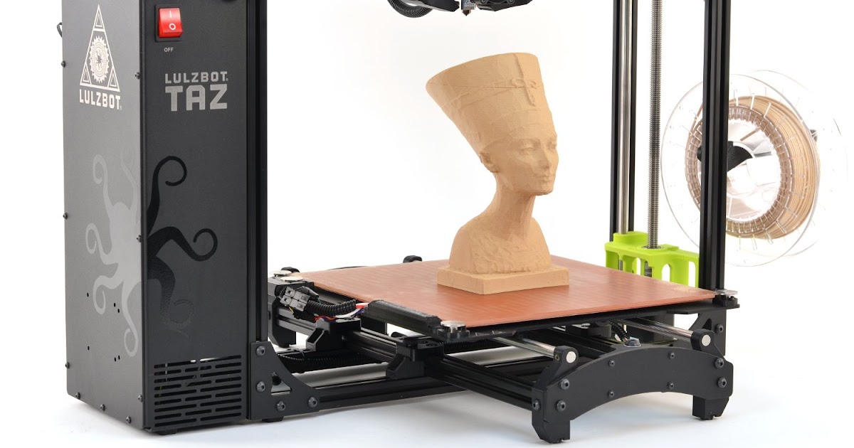 Depending on the object with which we work, the wishes for cameras may vary, however, in most cases these will be just wishes, not requirements. Even the simplest of them will solve the problem, perhaps with less accuracy than the optimal one, or require more images.
Busts of scientists on the alley in front of the main building of Moscow State University were photographed with a Sony NEX-5 camera. For shooting from the top point, a 1.8 m long rod and a remote control were used. For processing, a computer with an i5 11400F and an NVIDIA GeForce GTX 1650 GPU manjaro OS and open source programs Meshroom and COLMAP + OpenMVS were used. Details about installing programs and working with them in my article Accessible photogrammetry.
Meshroom is a GUI for AliceVision and requires an NVIDIA GPU.
COLMAP has an option to disable GPU usage. It is possible to work together with OpenMVS (Multi-View Stereo), which in turn supports work both with and without a GPU.
Meshroom and COLMAP + OpenMVS produced models in a reasonable time, which, after minimal retouching in Blender, were successfully presented on the Internet and printed on a 3D printer. Processing of 54 snapshots by COLMAP+OpenMVS CUDA-ON programs took 41 minutes, of which 31 minutes were taken by OpenMVS. Despite the fact that the COLMAP program is compiled with (CUDA_ENABLED "Whether to enable CUDA, if available" OFF ), it uses the GPU, and if you uncheck use_gpu in Processing/Feature extraction and Processing/Feature matching/, then the processing time will increase from 10 up to 16 minutes. OpenMVS without CUDA increased the computation time from 31 minutes to 53. The file size is over a gigabyte and optimization is needed, for example, using the MeshLab program and retouching in Blender. With Meshroom, this task took 49minutes with outwardly with almost identical quality. At the same time, the mesh was much better filtered and the file was 160 MB, but the texture files were twice as large. Those. the number of vertices is by no means proportional to the quality of the model.
For web demonstration, the result has been greatly simplified to reduce the file size to 6 MB. You can view the bust of Lobachevsky in detail from all sides in my gallery using the model-viewer program.
The cutting into layers was carried out in the Cura 4.13 program in Special Modes Spiralize Outer Contour with a nozzle with a diameter of 1 mm with a layer thickness of 0.15 mm with 5 layers at the base. In the latest version of Cura 5, it was not possible to achieve more than one layer in the base in this mode. Printing time 10 cm bust 2 hours. The result is in the photo below.
The time of creating scanning systems designed to provide scanning due to optical illumination systems and mechanical movement systems for the sake of using a computer that is weak in modern times has passed. The use of the scanners I described earlier is no longer appropriate. Can be disassembled for parts or sent to a museum. The available open source software provides the result with an arbitrary digital camera. The creation of specialized hardware systems for scanning makes sense to increase speed and quality, and not for the sake of lightening the load on the computer. Marks and grid projection will remain relevant for scanning objects with a perfectly smooth surface, on which it is impossible to find control points. Multi-camera systems are relevant when it is necessary to scan moving objects.
Follow author
Follow
Don't want
27
More interesting articles
eleven
Subscribe to the author
Subscribe
Don't want
Good day, colleagues. Looking for an inexpensive scanner to help you model tricky...
Read more