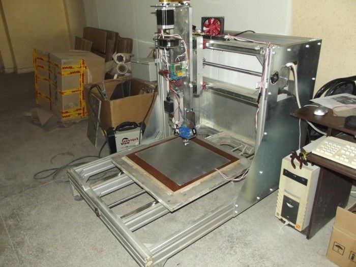
Mach4 3d printer
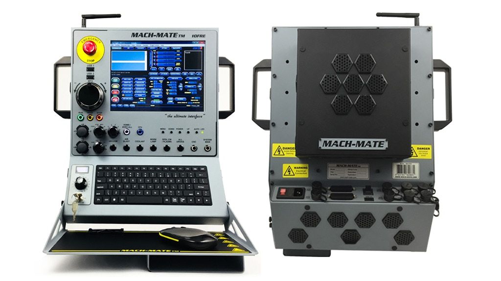
Newfangled Solutions Mach5
Mach5 is our newest version of CNC motion control software.
Mach5 was written from the ground up to be expandable, flexible, and extremely responsive for use with very large files.
Mach4 was designed for simple hobby machines and still serves this purpose well. When quality, speed, and the ability to use or learn industrial style controls and methods are what is needed, Mach5 is the correct choice. While there was only one version of Mach4, Mach5 is offered in different versions. Each version of Mach5 is built upon the same core. The architecture of Mach5 is modular and allows for quicker development to expand the already large feature set that Mach5 offers. Mach5 has been in use on Industrial equipment running constantly for over two years.
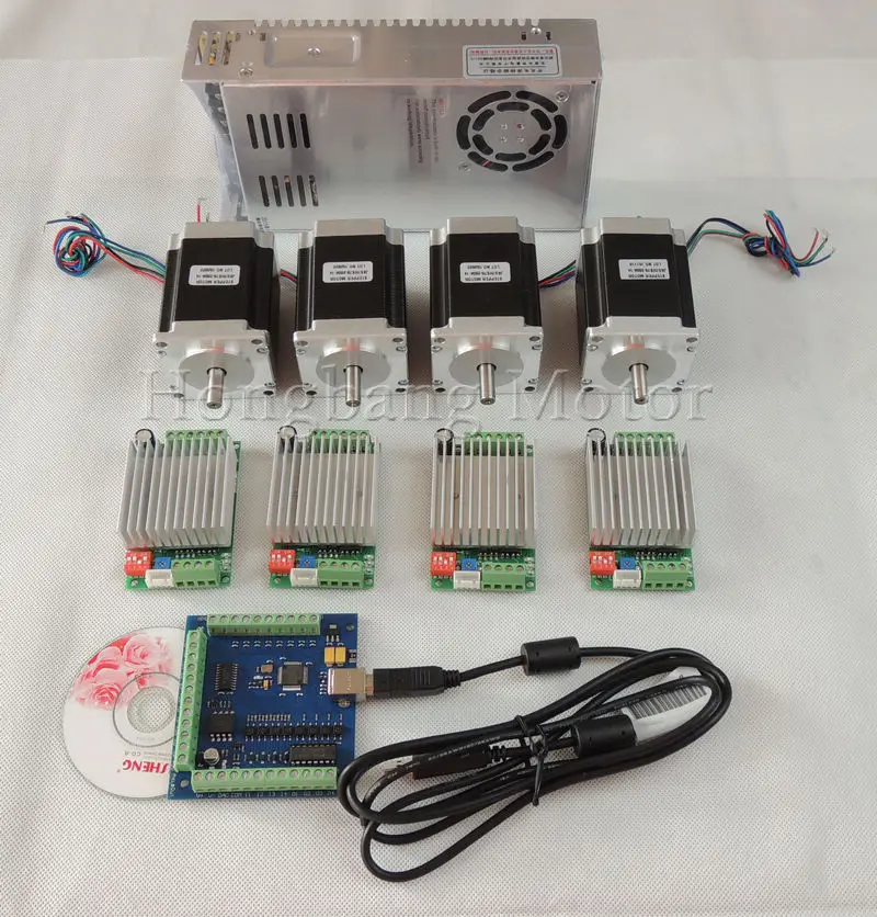
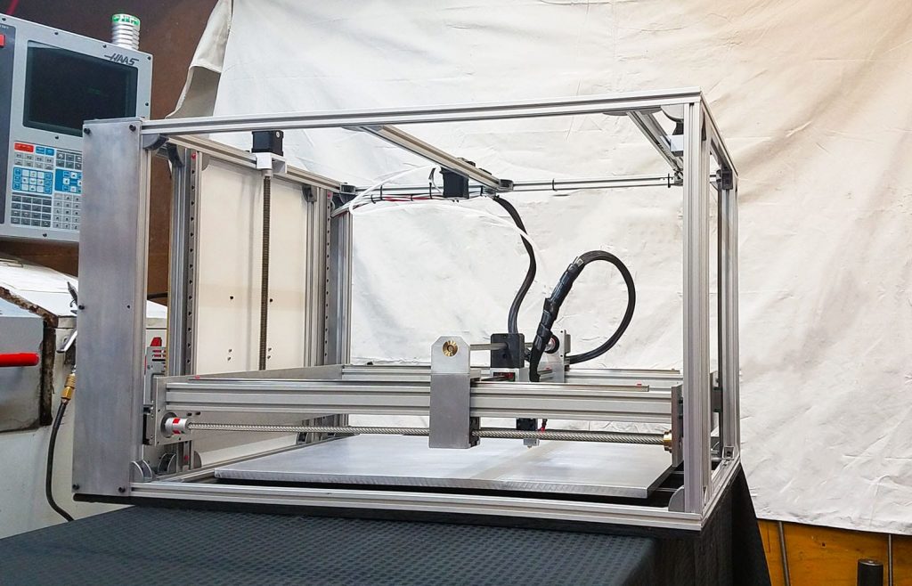
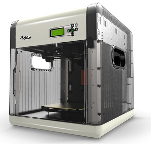
The standard Mach5 installer contains the screens and profiles to run Mills, Drills, Lathes, Routers, Tangential knife, Plasma, and 3D Printer machines. The full list of machines being controlled by Mach5 is much longer, but these machines can quickly be setup with the profiles and screens available in the standard Mach5 installer. Laser is the next machine to get a full profile for easy setup.
- Screens
- Download
- Licensing/Demo Mode
- Requirements
- Design
- Features
- Pricing
- Support
Download
The software is found on our main Download Page. The software is the full version and operates in Demo mode until licensed.
The current version supports the following;
- Running up to 6 axis machines
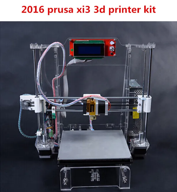
- Operating: Mills, Drills, Lathes, Routers, Tangential knife, Plasma, and 3D Printers
- Beta testing: Laser Systems
Download Software
Supporting Documents
After you have installed Mach5, you can find a configuration and a gcode manual in the directory where you installed Mach5. The normal location is C:\Mach5Hobby\Docs\.
From Mach4 to Mach5
Mach5 is completely new! We cannot stress this enough: Mach5 is not an upgrade for Mach4. It is faster, more responsive, and provides a platform for expansion, modification, and new features. The changes requested by many Mach4 users were simply not able to be completed because of limitations in the Mach4 code. Mach5 is our response to the limitations and requested changes for Mach4.
Hardware plugins (drivers) are created and supplied by the hardware manufacturer. Mach4 drivers and code are Not compatible with Mach5. Make sure the devices you will use have plugins available for Mach5.
Licensing Instructions
- Install the Demo on the Actual Machine it will be used
- Run the demo and go to the Help/about screen in Mach5
- Use the PC ID code from the Help/About screen at checkout to license this single computer. Additional licenses can be created after the initial purchase from within your account.
The license is linked to a specific PC, requiring a different code for each PC. Use the ‘About’ screen, accessed by the ‘Help’ menu to get the PC code. You must have this exact PC code from the actual PC you wish to license and generate G-code. To obtain your license key, Click the ‘copy ID to Clipboard’ button in the ‘about’ dialog box when running the software in demo mode and paste this ID number in the appropriate location on the website when purchasing your license.
IMPORTANT NOTE: The LICENSE will only work for the Computer for which you supplied the PC ID. Each PC has a unique ID code and the license works in coordination with this code.
If you upgrade or exchange your PC, it will be necessary to contact the distributor you purchased the license or create a new license yourself by logging into your account and using our website license maintenance feature.
PREFERRED: 32 or 64-bit Laptop or Desktop – Using an External Motion Controller
- Windows 10, Windows 8, Windows 7, Windows XP*
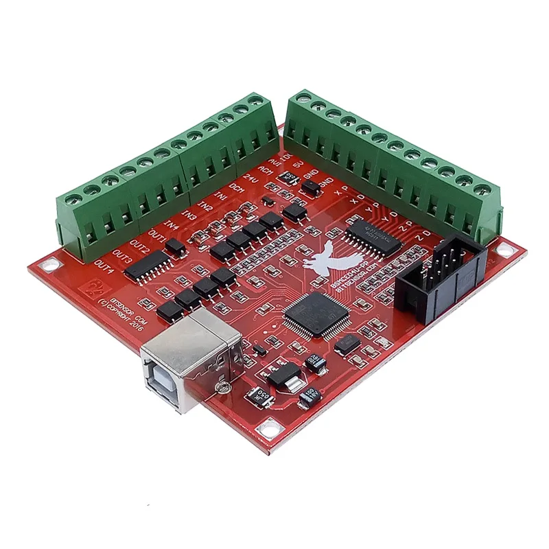
- An appropriate external motion controller
- Mach5 Plugin for the selected Motion Controller
- 2Ghz CPU
- 1GB RAM
- Video Card with 256MB RAM(Large G-code files, especially 3D files will require a video card with 512MB RAM or higher)
*Windows XP users should use version 4. 2.0.4162
NOTE: Using the Parallel Port for machine control works with desktop style computers with 32-bit versions of windows 7 and XP.
32-bit Desktop – Parallel Port Recommended Requirements
- 32-bit version of Windows 7, or Windows XP*
- Mach5 Parallel Port Legacy Plugin (cost applicable)
- 2Ghz CPU
- 1GB RAM
- Non-integrated Video Card with 256MB RAM(Large G-code files, especially 3D files will require a video card with 512MB RAM or higher)
*Windows XP users should use version 4.2.0.4162
Purchase Mach5-Hobby License Purchase Parallel Port PluginModular Design
Mach5’s modular design allows features to be added and removed without affecting the systems operation. This aspect greatly enhances the flexibility for different applications, machines and uses.
– Different modules of the core can be removed, added, or created to create a custom software package for OEM’s, re-sellers, and educational organizations.
– Everything is customizable, Make the software your Own
- Create Proprietary add-ons for your version
- Custom Installers
- Rapid Application Development (RAD) with our Screen Design Mode
- Increase or decrease functionality with Plug Ins and Add-ons
- Customizable M Codes for Machine Specific Functions
– No fixed amount of IO
- IO registered to system without any software interference between devices.
Mach5 can control CNC machinery, PLC equipment, and robotics. The core is a full featured ‘brain’ that ensures all input and output devices are coordinated with motion.
All Motion control calculated in the core = less dependence on hardware and associated software driver.
Motion Device Drivers (Plug Ins) have standard format = common level of functionality between components, less complexity, easier and less costly to troubleshoot and support.
Motion Control at the Core
All motion control calculations are completed in the core. Mach5’s core adapts to the speed (frequency) of the motion controllers attached. Mach4 software relied on the hardware plug-in software and complex buffering schemes to ensure accuracy and coordinated motion. This redesign has several advantages.
- Up to 100x faster response from button click to machine action
- Machine hold or speed changes happen as quickly as GUI buttons are selected on the screen
- Improved Backlash Control & more accurate screw mapping = less jitter and more accurate cuts
- Higher quality manual pulse generator (MPG) = very smooth jogging and positioning without lag time
Some New Features
- Type C (Fanuc) cutter compensation standard in Mach5
- More accurate tool path compensation for different size tools
- Improved Anti-gouging
- Synchronous Motion of up to 6 completely separate coordinate systems (instances) at the same time
- Multiple heads, machines and processes to produce complex parts
- Asynchronous Motion (out of band axis) to control uncoordinated motion
- Pre-change tool changers
- Robotic Loaders
- Torch height manual compensation control
- Multi-Axis Work Shifts and Head shifts to offset cutting tool path for multiple work piece holders and fixtures.
 - Remote Control of machinery (IPC)
New Features Continued
- Control or track CNC equipment from a remote location
- Greatly expanded troubleshooting
- Track the operation of equipment
- Link information between other computer applications
- Excel, etc…
- New Dynamic tool path display
- View, rotate, pan, and scale the tool path quickly and easily to ensure G-code is creating the path you expect.
- Improved screen layout and easily customizable screen modification tool.
- Change buttons, displays, and indicators easily, quickly, and on the fly!
A full featured software version with greatly expanded customer support, including phone support for customers in a manufacturing environment where every second counts.
Mach5 Industrial includes Macro B gcode programming, tool life management, screw mapping, and an advanced GUI editing tool.
*Customized or OEM versions will be offered for each of the products listed above.
Purchase a License
A full featured software version to be marketed toward those interested in using CNC machinery for their own personal /non-business use.
End-user support is limited to e-mail and online forums. Add-ons, expandability, and updates will be available.
This version is the direct replacement for Mach4.
Purchase a License
Mach5 Hobby License Key – Gadgitech Trading
-
R 3,00000
R 3,000.00
Unit price/ per
Shipping calculated at checkout.
Default Title -
R 3,000.00 ZAR
Mach5 is our newest version of CNC motion control software.
Mach5 was written from the ground up to be expandable, flexible, and extremely responsive for use with very large files.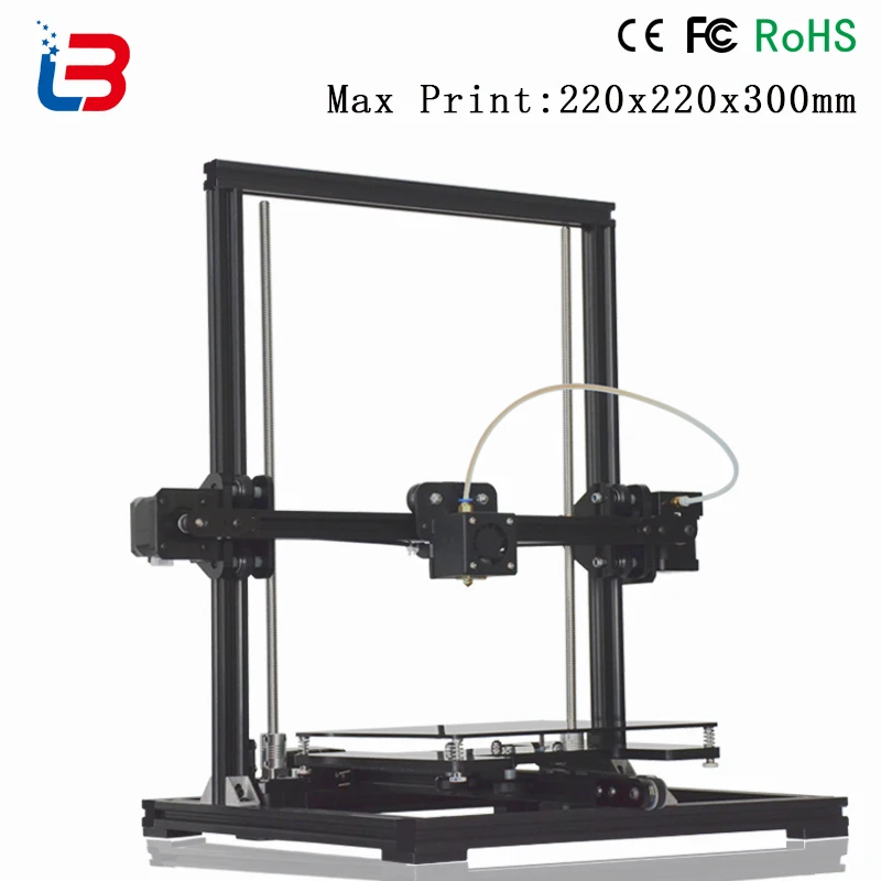
Mach4 was designed for simple hobby machines and still serves this purpose well. When quality, speed, and the ability to use or learn industrial style controls and methods are what is needed, Mach5 is the correct choice. While there was only one version of Mach4, Mach5 is offered in different versions. Each version of Mach5 is built upon the same core. The architecture of Mach5 is modular and allows for quicker development to expand the already large feature set that Mach5 offers. Mach5 has been in use on Industrial equipment running constantly for over two years.
The standard Mach5 installer contains the screens and profiles to run Mills, Drills, Lathes, Routers, Tangential knife, Plasma, and 3D Printer machines. The full list of machines being controlled by Mach5 is much longer, but these machines can quickly be setup with the profiles and screens available in the standard Mach5 installer. Laser is the next machine to get a full profile for easy setup.
Mach5’s modular design allows features to be added and removed without affecting the systems operation.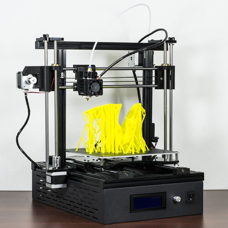 This aspect greatly enhances the flexibility for different applications, machines and uses.
– Different modules of the core can be removed, added, or created to create a custom software package for OEM’s, re-sellers, and educational organizations.
– Everything is customizable, Make the software your Own
- Create Proprietary add-ons for your version
- Custom Installers
- Rapid Application Development (RAD) with our Screen Design Mode
- Increase or decrease functionality with Plug Ins and Add-ons
- Customizable M Codes for Machine Specific Functions
– No fixed amount of IO
- IO registered to system without any software interference between devices.
Mach5 can control CNC machinery, PLC equipment, and robotics. The core is a full featured ‘brain’ that ensures all input and output devices are coordinated with motion.
All Motion control calculated in the core = less dependence on hardware and associated software driver.
Motion Device Drivers (Plug Ins) have standard format = common level of functionality between components, less complexity, easier and less costly to troubleshoot and support.
New Features Continued
- Control or track CNC equipment from a remote location
- Greatly expanded troubleshooting
- Track the operation of equipment
- Link information between other computer applications
- Excel, etc…
- New Dynamic tool path display
- View, rotate, pan, and scale the tool path quickly and easily to ensure G-code is creating the path you expect.
- Improved screen layout and easily customizable screen modification tool.
- Change buttons, displays, and indicators easily, quickly, and on the fly!
Motion Control at the Core
All motion control calculations are completed in the core. Mach5’s core adapts to the speed (frequency) of the motion controllers attached. Mach4 software relied on the hardware plug-in software and complex buffering schemes to ensure accuracy and coordinated motion.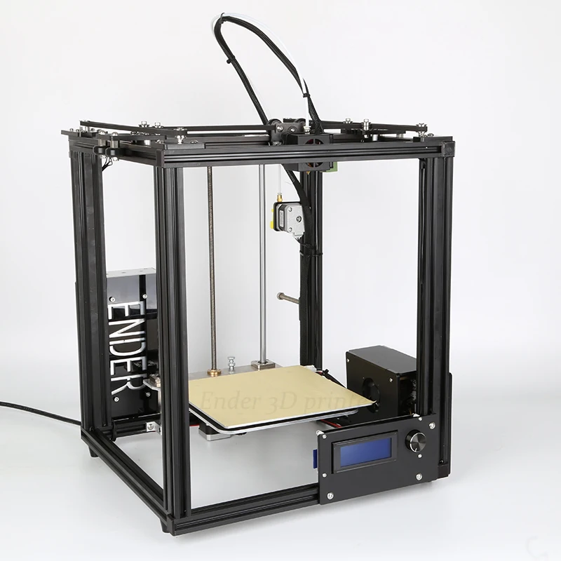 This redesign has several advantages.
- Up to 100x faster response from button click to machine action
- Machine hold or speed changes happen as quickly as GUI buttons are selected on the screen
- Improved Backlash Control & more accurate screw mapping = less jitter and more accurate cuts
- Higher quality manual pulse generator (MPG) = very smooth jogging and positioning without lag time
A full featured software version to be marketed toward those interested in using CNC machinery for their own personal /non-business use.
End-user support is limited to e-mail and online forums. Add-ons, expandability, and updates will be available.
This version is the direct replacement for Mach4.
* Please note that there will be no refund on any license key purchases.
* The license key will be emailed to the customer within 24 hours.
* Details needed to complete license key registration: Name, Surname and email address.

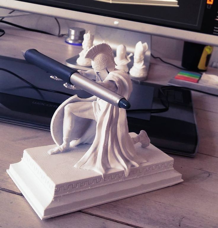
Drawing 3D Icons I will try to reveal this simple secret :)
I don’t give a detailed description of what and where to click, it would require writing a whole series of lessons, but I want to share a general principle.
I took an icon from the current project as an example.
The Rizzoma service is a collaboration system, an alternative to Google-wave.
During the work on the site, the idea was born to make beautiful icons for each block with the benefits of the service. The snail symbolizes contextual messages and is essentially an advanced symbol @
Usually, work on an icon starts with a pencil sketch, but this time it turned out to be quite inspirational Fast snail images. It was decided to make their own version of the turbine snail - beautiful and charming.
The model is usually in 3D Max, but in fact the tool is not critical. With the same success it could be done in Maya or Blender.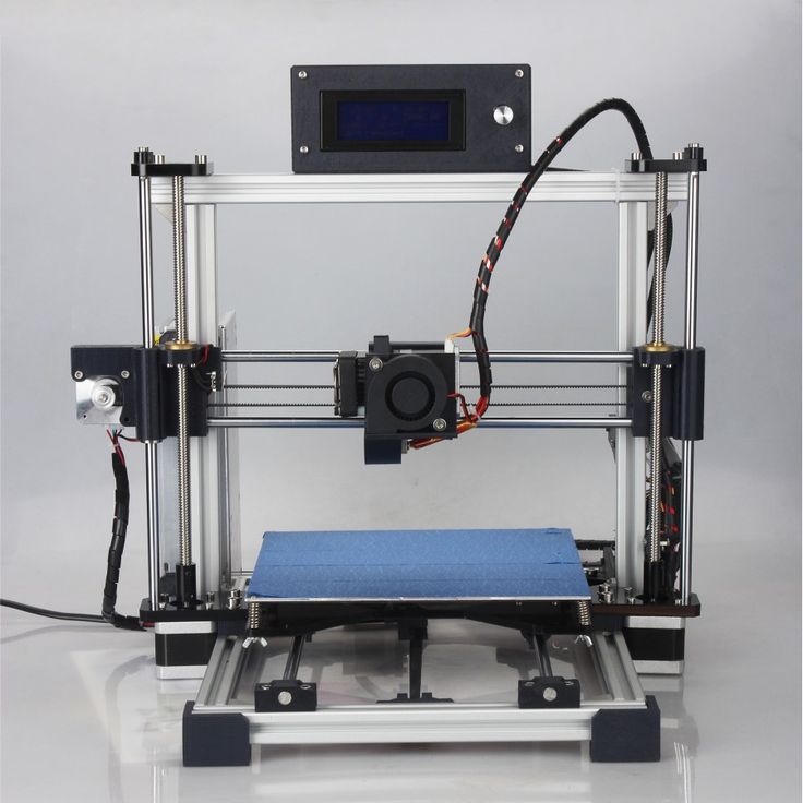
Sink
The model is made rough low-poly, then anti-aliasing is applied.
Slug and Turbine
Similarly, we make the soft part of the snail. For the turbine, smoothing is not necessary, you can immediately do it with a dense mesh.
Finished model
Putting it all together
Rendering with Vray, it's better to take a fresher version so that there are fewer bugs and everything goes faster.
Scene
I'm using a fairly standard C-shaped stage with three lights. It allows you to get a render that is not too noisy with good reflections at a high rendering speed. A tutorial on creating such a scene can be viewed, for example, here. I added two more lights, one blue, one yellow, to make color highlights and add "drama". Here you can see that the “strap” for attaching the turbine has been slightly modified.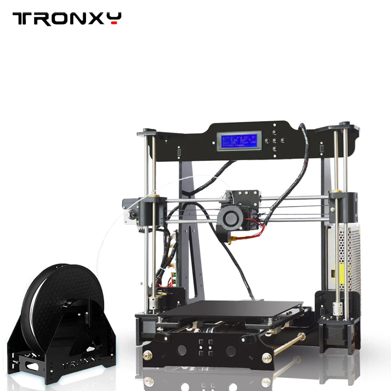
Texturing
Find the image of the snail you like and parse it
into two textures. We translate the texture into black and white, slightly increase the contrast and get a bump (texture of irregularities) I apply the textures without scanning, because the model will not animate and the view will be from only one angle. We set the desired degree of reflection and transparency. There is a chic site http://www.vray-materials.de with a lot of quality materials for Vray. You can use ready-made ones or take as a basis for creating your own.
Render
I render the image in a higher resolution than required in order to further reduce and “finish” it after processing. This results in a better end result, less noise and sharper details.
Masks
Additionally, the alpha channel and masks for different objects are rendered.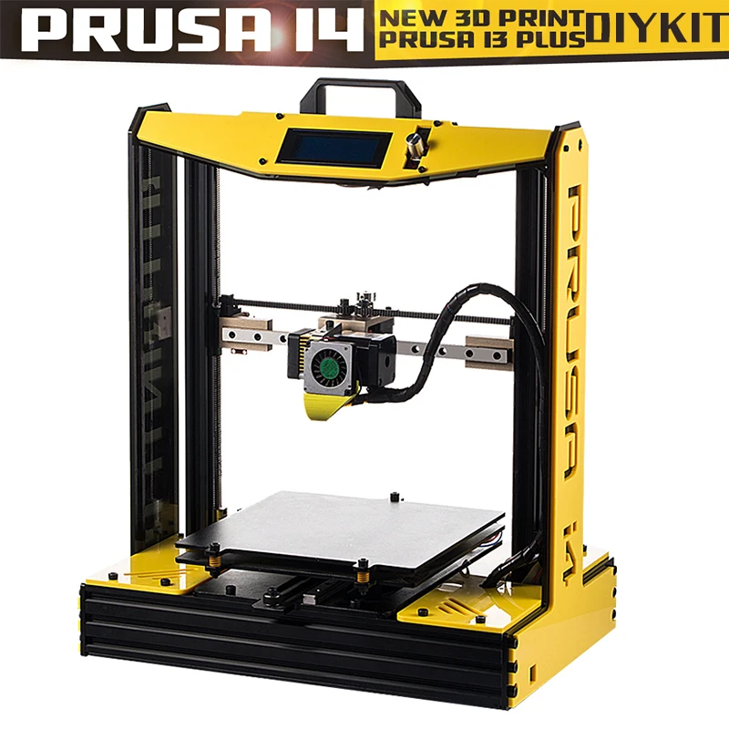 Theoretically, masks can be considered one channel by distributing the appropriate IDs to the necessary materials (or objects), but it’s convenient for me individually.
Finished, quite dirty and untidy, render corrected in Photoshop:
- Using the alpha channel, we cut out the object from the background
- We make the background lighter and more contrast, remove the excess, leaving only the shadow
— Using masks, we cut objects into separate layers
- We process each object, make it brighter, more contrast, add highlights, correct the shape, etc. It is difficult to draw up an exact algorithm for these actions, everything is done “by eye” and depends on what material is being processed and what you want to get
Slightly reduce and sharpen.
The big snail will be used for articles, the small one on the main page.
bmp - from English to all languages
Interpretation Translation
-
61 pixel image
pixel image Pixelgrafik f (Farbrasterbild-Darstellung mit Größen- und Farbtiefenangabe; z.
 B. 640 x 480 16 bit; Dateiendung.bmp)
 English-German dictionary of Electrical Engineering and Electronics > pixel image
-
62 viewer
viewer Bildbetrachter m , Bildbetrachtungsprogramm m (für BMP-, GIF- und JPEG-Dateien)
English-German dictionary of Electrical Engineering and Electronics > viewer
-
63 DIB format
Raster graphic file format used by Windows. DIB is an abbreviation for "Device-independent bitmap". A graphic image saved in DIB format has the extension .bmp or .dib. It is called “device-independent” because the colors are represented in a format that is independent of the final output device. When a DIB-formatted image is output to a monitor or printer, the device driver translates the DIB colors into colors available to the output device. Not to be confused with DIB - “ Dual Independent Bus” bus architecture of Intel's Pentium Pro and Pentium II microprocessors.
 0004
0004 English-Russian terms in computer graphics and 3D > DIB-format
-
64 file format
file format
The principle of organizing data in a computer file. Popular graphic file formats are BMP, PICT and TGA. Known 3D file formats include MAX, LWO, OBJ, 3DS, and DFX.
English-Russian terms in computer graphics and 3D > file format
-
65 maps
cards
images assigned to materials as specific patterns. For example, 3DS MAX 4 has several types of maps. These include standard bitmaps (.bmp, .jpg, or .tga format), procedural maps (such as Checker or Marble), and image processing systems such as combiners and masking systems.
English-Russian terms in computer graphics and 3D > maps
-
66 texture
texture
See texture map.
A two-dimensional image stored in the memory of a computer or graphics accelerator in one of the pixel formats.
 If stored in a compressed form on computer disks, the texture can be a regular bitmap, which we are used to seeing in bmp, jpg, gif, etc. formats. Before use, the texture unfolds in memory and can take up ten times the original size. There are about two dozen more or less standardized pixel texture formats.
 English-Russian terms in computer graphics and 3D > texture
-
67 .DIB
( Device-Independent Bitmap ) Microsoft graphics file similar to .BMP
English-Russian explanatory dictionary of terms and abbreviations on BT, Internet and programming. > .DIB
-
68 bitmap
= bitmap; = bit map
1) bit (bitmap) display of a graphic object, bitmap graphic format
is used to represent images, in particular fonts
see also. bitmapped font, BMP, dot matrix, logical bitmap
0101
see also bitmapped graphics
English-Russian explanatory dictionary of terms and abbreviations on BT, Internet and programming.
 > bitmap
 -
69 graphics file
graphic file
file containing a graphic image. There are many formats for such files, the most common of which are BMP, CGM, DXF, EPS, GIF, PIC, PCX, TIFF, WMF
English-Russian explanatory dictionary of terms and abbreviations on BT, Internet and programming. > graphics file
-
70 PCX
I
PCX format, PCX file
A common graphic file format for color bitmaps developed by Zsoft Corporation for the Paintbrush package. The image is compressed to 1:1.5. The maximum file size is 64K by 64K points. Supported by the vast majority of graphic editors
see also BMP, graphics file, TIFF
II
(file extension) (Picture Image) bitmap graphics package format PC PaintBrush and many others
English-Russian explanatory dictionary of terms and abbreviations on BT, Internet and programming.
 >PCX
>PCX -
71 TIFF
I
(Tag Image File Format) TIFF
standard format for compressing and storing raster image files (graphic files) developed by Aldus and Microsoft. Supported by almost all graphics packages
see also. BMP, DCS, file format, PCX
II
(file extension) see TIF
English-Russian explanatory dictionary of terms and abbreviations on BT, Internet and programming. > TIFF
-
72 WMF
I
(Windows Metafile Format) Windows Metafile Format WMF format0204 NIS
see also BMP, DIB, EMF
II
(file extension) (Windows Metafile Format)
English-Russian explanatory dictionary of terms and abbreviations on BT, Internet and programming.
 > WMF
> WMF -
73 batch message processing
n ↑ BMP COMP Stapelnachrichtenverarbeitung f
Dictionary English-German Informatics > batch message processing
-
74 bit map
n ↑ BMP COMP result of bit mapping Bitmap f
Dictionary English-German Informatics > bit map
-
75 flat file format
"An image file format in which individual objects cannot be edited. Files stored in JPEG, GIF, and BMP formats are all flat files. The PhotoDraw MIX file format is not a flat file format."
ملف ثابت
English-Arabic terms dictionary > flat file format
-
76 bitmap
- bitmap
- bitmap
- bitmap
bit map
bit array
An image image on a graphic device, presented in a special form and stored in the computer memory or on an external device.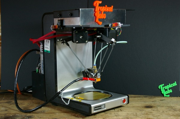
[E.S. Alekseev, A.A. Myachev. English-Russian explanatory dictionary of computer systems engineering. Moscow 1993]Topics
- information technology in general
Synonyms
- bit array
EN
- bitmap
bitmap
bitmap
A file format for storing images in which each data element corresponds to a single pixel value.
[L.M. Nevdyaev. Telecommunication technologies. English-Russian explanatory dictionary-reference book. Edited by Yu.M. Gornostaev. Moscow, 2002]Topics
- telecommunications, basic concepts
Synonyms
- bitmap
EN
- bitmap
bitmap Smaller dots show light areas, larger dots show dark areas. Black and white images are reproduced using only black dots, while color images are reproduced using cyan, magenta, yellow, and black dots (CMYK).

[ http://www.morepc.ru/dict/]
bitmap
A graphic image on a display screen or on a printer, represented as an array of bits (zeroes and ones).
[ http://www.morepc.ru/dict/]
raster image
This is a data file representing a rectangular pixel grid. It determines the location and color of each pixel (or bit) on the screen. This type of image is also called raster graphics. The GIF and JPEG formats are examples of file types that contain a bitmap.
Because this type of image uses a fixed raster method, it cannot be scaled without loss of clarity. Unlike raster graphics, vector graphics use geometric shapes to reproduce them, allowing for quick scaling.
[http://www.alltso.ru/publ/glossarij_setevoe_videonabljudenie_terminy/1-1-0-34]
bit mapping
Pixel description of the image. Each pixel is treated as a separate element.- supervisory control and data acquisition
- SCADA
supervisory control and data collection
Subsystem for collecting, storing and processing telemetric information from remote sensors that measure temperature, pressure, power consumption, etc.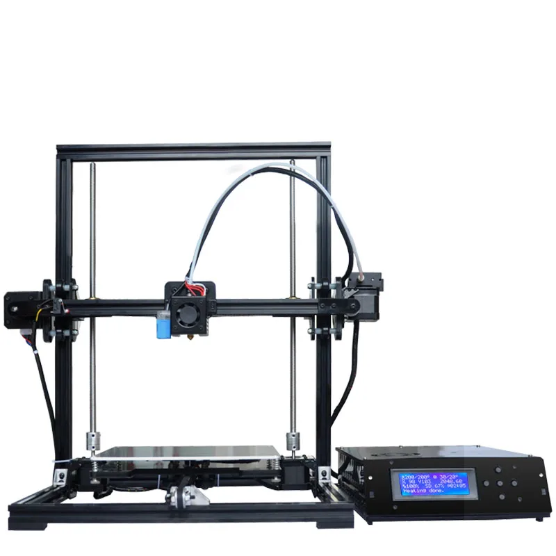 Data collection is carried out using controllers, the software of which makes it possible to implement any algorithm for polling sensors, as well as provide primary processing of information. Communication is often carried out via the RS-485 interface. The term SCADA is usually used when it comes to the control and regulation of any production processes.
[http://www.morepc.ru/dict/]
SCADA (abbr. from English supervisory control and data acquisition, supervisory control and data collection) is a software package designed to develop or ensure real-time operation of systems for collecting, processing, displaying and archiving information about a monitoring or control object. SCADA can be a part of APCS, ASKUE, environmental monitoring system, scientific experiment, building automation, etc. SCADA systems are used in all sectors of the economy where it is required to provide operator control over technological processes in real time. This software is installed on computers and uses I/O drivers or OPC/DDE servers to communicate with an object.
 Program code can be either written in a programming language (for example, C++) or generated in a design environment.
 Sometimes SCADA systems are equipped with additional software for programming industrial controllers. Such SCADA systems are called integrated and the term SoftLogic is added to them.
The term "SCADA" has two meanings. The most widespread understanding of SCADA as an application[2], that is, a software package that provides the performance of these functions, as well as tools for developing this software. However, often a SCADA system is understood as a software and hardware complex. Such an understanding of the term SCADA is more typical for the telemetry section.
The meaning of the term SCADA has changed with the development of automation and process control technologies. In the 80s, SCADA systems were more often understood as software and hardware systems for collecting real-time data. Since the 90s, the term SCADA has been more used to refer only to the software part of the human-machine interface of the process control system.

Main tasks solved by SCADA systems
SCADA systems solve the following tasks:
- Communication with "object communication devices", i.e. with industrial controllers and I / O boards) in real time through drivers.
- Processing of information in real time.
- Logic control.
- Displaying information on the monitor screen in a form that is convenient and understandable to humans.
- Maintaining a real-time database of technological information.
- Alarm signaling and management of disturbing messages.
- Preparation and generation of reports on the progress of the technological process.
- Implementation of network interaction between SCADA PCs.
- Providing communication with external applications (DBMS, spreadsheets, word processors, etc.). In the enterprise management system, such applications are most often applications related to the MES level.
SCADA systems allow you to develop automated process control systems in a client-server or distributed architecture.

SCADA main components
A SCADA system typically contains the following subsystems:
- I/O drivers or servers are programs that provide SCADA communication with industrial controllers, meters, ADCs and other information input/output devices.
- A real-time system is a program that provides data processing within a given time cycle, taking into account priorities.
- Human Machine Interface (HMI) is a tool that presents process progress data to a human operator, allowing the operator to control and manage the process. Program-editor for the development of human-machine interface.
- Logic control system is a program that ensures the execution of user programs (scripts) of logical control in a SCADA system. A set of editors for their development.
- Real-time database is a program that provides real-time process history saving.
- An alarm management system is a program that provides automatic control of technological events, classifying them as normal, warning or emergency, as well as processing events by an operator or computer.

- Report Generator - a program that provides the creation of custom reports on process events. A set of editors for their development.
- External interfaces are standard interfaces for data exchange between SCADA and other applications. Typically OPC, DDE, ODBC, DLL, etc.
System Concepts
The term SCADA generally refers to centralized systems for controlling and managing an entire system, or collections of systems, with human intervention. Most control actions are performed automatically by the RTU or PLC. The direct control of the process is usually provided by the RTU or PLC, while the SCADA manages the modes of operation. For example, a PLC can control the flow of cooling water within a part of a manufacturing process, and a SCADA system can allow operators to change flow setpoints, reroute liquids, fill containers, and monitor for alarms such as loss of flow. and high temperature, which must be displayed, recorded, and to which the operator must respond in a timely manner.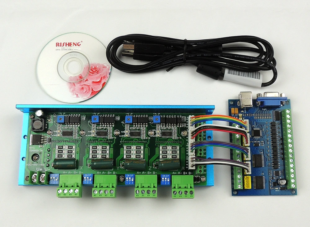 The closed-loop control loop passes through the RTU or PLC while the SCADA system controls the complete execution of the loop.
 Data acquisition starts at the RTU or PLC level and includes - meter readings. Further, the data is collected and formatted in such a way that the control room operator, using the HMI, can make control decisions - to correct or interrupt the standard control of the RTU / PLC facilities. The data can also be archived for trending and other analytical processing of the accumulated data.
[http://en.wikipedia.org/wiki/SCADA]
CitectSCADA
Supervisory Control And Data Acquisition (SCADA)TECHNICAL DATA:
CitectSCADA is built on a real-time multi-tasking engine that provides up to 5,000 values per second acquisition performance when networked with multiple stations. The modular client-server architecture allows CitectSCADA to be equally effectively used both in small projects, using only one workstation, and in large ones, with the distribution of tasks to several computers.
Unlike other SCADA systems, the CitectSCADA development environment is provided free of charge. Only the execution environment (runtime) is paid. This allows the user to develop and test a pilot project without the initial investment.
The CitectSCADA licensing scheme is based on the number of computers simultaneously involved in the project, and not the total number of computers on which CitectSCADA is installed.
CitectSCADA is licensed for a given number of points (discrete or analog variables). In this case, only external variables read from I/O devices are taken into account, and internal variables located in memory or on disk are free and are not included in the number of licensed points. The gradation of the number of licensed points in CitectSCADA is more uniform than in other systems: 75, 150, 500, 1500, 5000, 15000, 50000 and unlimited.
In CitectSCADA, redundancy is built-in and highly configurable.
 Redundancy allows you to protect all zones of potential failures of both functional modules (servers and clients) and network connections between nodes and input/output devices.
 CitectSCADA has a built-in CiCode programming language as well as VBA support.
CitectSCADA runs as a 32-bit Windows 9X/NT/2000/XP/2003 application. Data collection, alarm generation, and trending occur simultaneously with editing and compilation.
[http://www.rtsoft.ru/catalog/soft/scada/detail/343/]
Word portrait of modern control system type SCADA- Scalable
- System expansion without reconfiguration
- The scope of the project is not limited
- Up to 255 simultaneously connected clients
- LAN and WAN support
- Ability to integrate with web applications without system configuration
- Possibility of functioning at a low throughput of communications
- Support for cluster configurations
- Ability to restart individual processes related to different components
- Flexible
- Complete client-server architecture
- Ability to scale servers/server arrays of alarms, trends and reports
- Support for centralized storage of project files for ease of maintenance, as well as distributed storage and combined option
- Making changes to individual locations
- Possibility of functioning at a low throughput of communications
- Support for established and new standards
- Reliable
- Built-in standby support
- Redundant file servers
- Network communications redundancy
- Alarm server redundancy
- Redundant trend servers
- Report server redundancy
- Multi-level I/O redundancy
- Automatic server replacement
- Automatic synchronization of trend histories
- Automatic synchronization of alarm tables
- Automatic time synchronization
- Protective functions
- Automatic restart in case of system failure
- High Performance
- Acceptable performance for projects of all sizes
- Low processor and memory requirements
- Low network load
- Support for multiprocessor configurations
- Safe
- Security settings for individual users and user groups
- Up to 250 concurrent users
- Unlimited usernames
- Setting a set of rights and privileges for each username
I/O
- Communication Technology
- Support for open communication standards
- Multiple protocols supported by each I/O server
- Protocol drivers RS-232, RS-422, RS-485, TCP/IP
- Driver installation time within 60 seconds
- Up to 255 simultaneously connected clients
- Up to 4096 I/O devices per system
- External connection support for remote devices
- Driver development tools for custom protocols
- Support for OPC Server DA2.
 0
0 - XML Integrated Web Service
- Access
- Drivers available at no extra cost
- New versions of drivers are posted on the site
- Driver update support
- High speed access
- Dynamic optimization for all drivers
- Read data on request
- Up to 100000 integers per second
- Update from I/O devices
Tags
- Unlimited Tags
- Label name length up to 80 characters
- Quality and timestamp support for related drivers
- Unified database for PLC controllers and SCADA system
- Bidirectional synchronization with PLC development environment
- Static synchronization for offline development
- - Automatic import and synchronization
- Import from PLCs of various types
- Adding custom import schemas
Graphics
- Development
- Unlimited screens
- 24-bit colors
- Quick selection of colors by name
- Support for transparent colors
- Advanced animation without additional programming
- Animation of symbols based on tags
- Up to 32000 animated images per page
- Unlimited flashing colors
- Multilingual
- 3D Pipe Tools
- 3D effects (raise, lower, extrude)
- Import graphics
- Windows Bitmaps (BMP, RLE, DIB)
- AutoCAD Format (DXF)
- Encapsulated Postscript (EPS) format
- Fax Image (FAX) Format
- Ventura format (IMG)
- JPEG format (JPG, JIF, JFF, JFE)
- Photo CD (PCD) format
- PaintBrush Format (PCX)
- Portable Network Graphics (PNG) format
- Targa format (TGA)
- Tagged Image Format (TIFF)
- Windows Meta File (WMF) Format
- Word Perfect Graphics (WPG) format
- Unlimited number of undo actions
- Windows XP style buttons with dynamic navigation properties
- Templates
- Large number of templates in different styles and resolutions
- Stretching templates with graphics tools
- Templates can contain animation
- Changes to templates are reflected on all pages
- The same templates can be used in different projects
- Symbols
- Over 800 characters included
- Creating user-defined symbols using the graphic toolkit
- Symbols may contain animation
- Changes to symbols are reflected in all their copies
- The same symbols can be used in different projects
- Object configuration
- Unlimited Genie and Super Genie objects
- User genies allow user equipment to be displayed on the screen
- Custom "supergins" allow you to work with different devices through one interface
- Objects of type "genie" and "supergenie" are able to accept changes in device tags without additional programming
- Work
- Resolutions up to 4096 x 4096
- Image resizing (isotropic and anisotropic)
- Multi-monitor output support
- Setting page refresh rate (minimum 10ms)
- Communication loss notification
- Switching languages during operation
- Single and double byte character set support
- Security
- Security level affects:
- Visibility of objects
- Access to graphic displays
- Alarm acknowledgment
- Generating reports
- System Utilities
Actions
- Control
- Touch commands
- Mouse
- - Keyboard control of the system, pages and animations
- Vertical and horizontal sliders
- Replacement OBD
- Process analysis
- Combining alarms with trends
- 32 or more nibs
- 4 or more window sections
- 2 or more cursors
- Feather overlay
- Data quality information
- Analog and digital pens
- Alarm acknowledgment information
- Description of alarms (analogue and multidigital)
- Alarm comments
- Daylight Savings Time Support
- Saving views while working
- Storage of views in remote locations
- Display of different time periods s x periods on the same display
- Customizable and expandable control
- Alarms
- Unlimited alarms
- Central alarm handling
- Alarms can be of the following types:
- Digital
- Analog
- Timestamps
- High-level expressions
- Multidigital
- Digital with timestamps
- Analog with timestamps
- Changing the language for all alarms during operation
- Network acknowledgment without additional configuration
- Network shutdown without further configuration
- Categories, Zones, and Alarm Priorities
- Alarm delays
- Assignment of timestamps s x with 1 ms resolution
- Miscellaneous data in alarms
- Individual and group confirmations
- Confirmations based on categories and priorities
- Acknowledgments are displayed graphically, in the alarm list or via a custom code:
- Alarm triage
- Alarm filtering
- Custom alarm fields
- Trends
- Unlimited Trends
- Up to 16000 trends per page
- Display any trend from history in less than 1 second
- Adjustable size trend files
- Viewing historical trends in parallel with the actual ones during the operation of the system
- 1ms resolution selection
- Trend comparison
- Quick selection of trends by tags
- Event save or periodic save
Statistical Control
- Control cards X, R and S
- Pareto charts
- Custom sizes and subgroup borders
- Alarm types: Above UCL, Below LCL, Outside CL, Down Trend, Up Trend, Erratic, Gradual, Down, Gradual Up, Mixture, Outside WL, Freak, Stratification and high-level expressions
Reports
- Generated report editor, WYSIWYN model editing, Rich Text reports
- Triggering by external events, by schedule, via high-level expressions and by operator command
- Output to printer, file, e-mail, screen, HTML
Configuration
- Project development
- The scope of the project is not limited
- Ability to split into multiple projects
- Convenient project standardization
- Convenient project management
- Built-in computer setup tool allows you to configure each networked PC individually
Software
- True preemptive multitasking
- Up to 512 parallel streams
- Over 600 SCADA functions available
- Libraries for user-defined functions
- Up to 2700 user functions
- Local, Modular, and Global Variables
- No additional software required to create your own functions
- Direct access to trend, report and alarm data
- Syntax highlighting
- Online Help System
- Tooltips
- Available for editing:
- Checkpoints
- Display variables
- Thread monitoring
- Code highlighting
- Breakpoint window
- Step by step execution mode
- Highlight the current line
- Remote debugging
- Automatic debugging in case of errors
Security
- Integrated Windows security at project level
Communication
- OPC server and client
- ODBC interface
- OLE-DB interface
- CTAPI interface
- Interface DLL
- MAPI interface (MAIL)
- Protocols TCP/IP
- Serial interface
[http://www. rtsoft-training.ru/?p=600074]
Topics
- automated systems
Synonyms
- Busy mode protocol
intensive exchange mode protocol
burst mode protocol
-
[L.G. Sumenko. English-Russian Dictionary of Information Technologies. M.: GP TsNIIS, 2003.]
Topics
- information technology in general
Synonyms
- packet mode protocol
EN
- burst mode protocol
- BMP
English-Russian dictionary of regulatory terminology > burst mode protocol
79 bit image
- bitmap
bitmap
To reproduce a grayscale original on a printing press, the image is divided into many dots of different sizes and colors (bitmap). Smaller dots show light areas, larger dots show dark areas. Black and white images are reproduced using only black dots, while color images are reproduced using cyan, magenta, yellow, and black dots (CMYK).
[ http://www.morepc.ru/dict/]
bitmap
A graphic image on a display screen or on a printer, represented as an array of bits (zeroes and ones).
[ http://www.morepc.ru/dict/]
raster image
This is a data file representing a rectangular pixel grid. It determines the location and color of each pixel (or bit) on the screen. This type of image is also called raster graphics. The GIF and JPEG formats are examples of file types that contain a bitmap.
Because this type of image uses a fixed raster method, it cannot be scaled without loss of clarity. Unlike raster graphics, vector graphics use geometric shapes to reproduce them, allowing for quick scaling.
[http://www.alltso.ru/publ/glossarij_setevoe_videonabljudenie_terminy/1-1-0-34]
bit mapping
Pixel description of the image. Each pixel is treated as a separate element.
- bitmap
bitmap
To reproduce a grayscale original on a printing press, the image is divided into many dots of different sizes and colors (bitmap). Smaller dots show light areas, larger dots show dark areas. Black and white images are reproduced using only black dots, while color images are reproduced using cyan, magenta, yellow, and black dots (CMYK).
[http://www.morepc.ru/dict/]
bitmap
A graphic image on a display screen or on a printer, represented as an array of bits (zeros and ones).
[ http://www.morepc.ru/dict/]
raster image
This is a data file representing a rectangular pixel grid. It determines the location and color of each pixel (or bit) on the screen. This type of image is also called raster graphics. The GIF and JPEG formats are examples of file types that contain a bitmap.