Lytro 3d scanner
3D light field technology | Raytrix
Raytrix Intellectual Property (IP)
Plenoptic Image Sensor with Raytrix Microlens Array (MLA)
1908 Nobel Prize Winner Lippmann
Integral Photography: Insect’s Compound Eye
Our light field cameras enable you to simultaneously record the 2D image and metrically calibrated 3D depth information of a scene with just a single camera and a single main lens in a single shot.
This typically works with standard lighting and even a flash. For difficult surfaces a pattern projector can also be used. The exposure time is only limited by the camera electronics and the available amount of light. The cameras perform no processing internally, they simply deliver a raw image to a PC, which is then processed on a GPU to obtain the 2D and 3D data.
In principle, we can turn any camera into a light field camera. Usually, one of our stock cameras will fulfill your needs, though. We have cameras with USB3, 10GigE or CoaxPress connection types, with different frame rates, resolutions and sensor sizes. Most cameras are available in color and mono version and some are available as NIR version. Have a look at our products page for a complete overview.
FAQ: How does it work? A: Very Good.
To obtain 2D and 3D data from a single shot, we need mainly two things: a micro lens array (MLA) and software algorithms.
The MLA is placed in front of the image sensor inside the camera, which turns the image sensor into a micro-camera array (see figure on right), where each micro-camera sees part of the intermediate image from a slightly different perspective. That is, instead of using a large camera array that looks at the object directly, we can choose a main lens to select the desired field-of-view and create the intermediate image in front of the micro camera array. The images generated by the camera in this setup are processed on a PC with appropriate software algorithms to calculate the scene depth and to reconstruct a 2D image.
We do all our processing on a GPU, which allows us to typically process 150 26 megaray raw images per second, resulting in 150x 6MP (megapixel) 2D & 3D images per second (150 FPS).
PreviousNext
Why would I want to use light-fields?
Our 3D light field cameras work particularly well for small objects. You can use a standard lens, a telecentric lens or a microscope to select desired field-of-view and depth resolution. The patented micro lens array offers an optimal combination of high effective resolution and extended depth-of-field. Since you only need a single camera and a single shot you can
- estimate the 3D position of objects situated deeply inside a cylindrical enclosure
- take images of moving objects at high frame rates using a flash or strobe
- obtain 3D data through a standard microscope in a single shot.
The effective lateral resolution is at most a quarter of the sensor resolution and the depth resolution is about 1% of the total depth-of-field. The absolute values depend on the main lens used. Typical application areas are:
- Automated optical 3D inspection in industry.
- Measurement of 3D flow with a single access point in fluid mechanics research.
- 3D Plant analysis for breeding, picking or weeding.
- 3D Microscopy for industrial parts.
PreviousNext
What else?
The no-free-lunch theorem also applies here: You can obtain 2D & 3D data in a single shot but you pay with effective lateral resolution. Our cameras have a maximal effective lateral resolution of about one quarter of the sensor resolution. This effective lateral resolution also varies over the whole depth-of-field. The camera is setup by focusing the main lens to the furthest plane you are interested in. From this plane towards the camera the depth can be calculated and a 2D image reconstructed. Everything that lies behind this plane can not be reconstructed at all. The effective lateral resolution is highest at the focus plane and drops as you get closer to camera.
The depth resolution is typically 1% of the total depth-of-field, which in turn depends on the focal length of the main lens and the focus setting.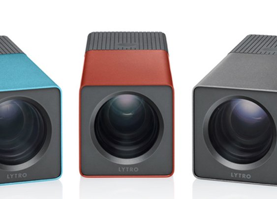 You can select different main lenses for the same light field camera to adjust the depth-of-field to your needs. However, the larger the field-of-view, the larger the depth-of-field and the closer you need to be to the main lens to obtain a good depth resolution. In particular, this means that a light field camera in combination with a wide-angle lens can only see depth differences close to the main lens.
On the other hand, light field cameras work well within the macro realm, with microscopes and also with telescopes.
For a basic introduction have a look at the posters we presented at the “Deutsches Museum” in Munich. More detailed technical information can be found in our scientific papers.
Downloads
3D Light-Field Vision
RGB-DepthExpress Sensors
Realtime Plenoptic Metrology-Software made in Germany
Lytro.com
Contact
Raytrix GmbH
Schauenburgerstrasse 116
DE 24118 Kiel
GERMANY
info@raytrix. de
de
Tel: 0049 431 5606 240
Fax: 0049 431 26090065
Search
Copyright © 2008 - 2023 Raytrix GmbH Germany. All rights reserved.
Raytrix 3D Light-Field Vision Plenoptic Metrology
| Example Application | Camera Model | Field-of-View Width (X) in mm | Field-of-View Height (Y) in mm | Depth-of-Field (Z) in mm | Minimal Working Distance in mm | Maximal Working Distance in mm | Lateral Resolution (X,Y) in microns | Depth Resolution (Z) in microns | Max. Frame Rate in FPS |
|---|---|---|---|---|---|---|---|---|---|
| Pin & Connector Inspection | R50 | 75 | 57 | 15 | 130 | 610 | 19 | 35 | 30 |
| Pin & Connector Inspection | R42 | 20 | 14 | 9 | 170 | 350 | 5 | 12 | 7 |
| Pin & Connector Inspection | R8 | 20 | 14 | 9 | 170 | 350 | 10 | 20 | 30 |
| Small Parts and Hard-to-Access Areas | R12macro | 22 | 17 | 15 | 250 | 400 | 11 | 20 | 330 |
| Flat Panel and Mobile Device Display | R50 | 90 | 68 | 16 | 135 | 660 | 23 | 50 | 30 |
| Semiconductor Solder Paste | R50macro | 12,1 | 9,2 | 1,1 | 48 | 3,1 | 1,5 | 30 | |
| Semiconductor Bonding Wires, PCBs, SMDs, MLCCs | R26macro | 7,8 | 7,8 | 1,1 | 48 | 3 | 2,5 | 80 | |
| Semiconductor MEMS Scanner | R12micro | 0,65 | 0,44 | 0,06 | 20 | 0,7 | 0,4 | 60 | |
| Small Parts Pick&Place and Bin Picking | R12 | 45 | 34 | 15 | 450 | 22 | 40 | 330 | |
| Pick & Place Robotics | R50 | 500 | 380 | 300 | 450 | 2100 | 160 | 800 | 30 |
| Gesture Recognition | R26 | 300 | 300 | 300 | 420 | 2000 | 140 | 600 | 80 |
| Face Recognition and Detection | R26 | 500 | 500 | 500 | 670 | 3200 | 250 | 1000 | 80 |
| Phenotyping and Plant Growth Research | R50 | 300 | 300 | 300 | 420 | 2000 | 140 | 600 | 30 |
| Microscopy Cell Characterization | R12micro | 0,22 | 0,15 | 0,01 | 0,19 | 0,25 | 0,25 | 60 | |
| PIV/PTV: Stent / Aneurysm Particel / Fluid Flow Mechanics | R12macro | 60 | 45 | 45 | 140 | 1000 | 30 | 150 | 330 |
| PIV/PTV Headlamp Flow Model | R12 | 300 | 225 | 300 | 430 | 2000 | 150 | 1000 | 330 |
| Example Application | Camera Model | Field-of-View Width (X) in mm | Field-of-View Height (Y) in mm | Depth-of-Field (Z) in mm | Minimal Working Distance in mm | Maximal Working Distance in mm | Lateral Resolution (X,Y) in microns | Depth Resolution (Z) in microns | Max. Frame Rate in FPS |
Design, features, and specifications are subject to change without notice.
Please let us know your individual Specifications...
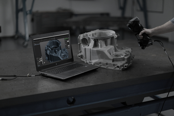
How Rexcan's 3D Scanner and Geomagic's Engineering Analysis Helped Recreate a Classic Car
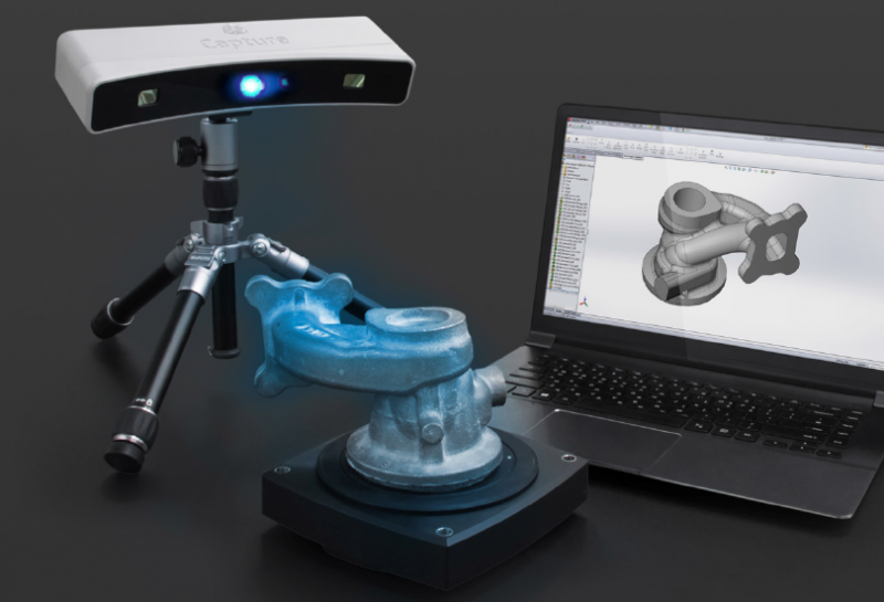
South Korean company Solutionix designs and manufactures high-precision 3D scanners that project white light beams onto the object being scanned. This technology allows you to get results unsurpassed in accuracy. In addition, Solutionix 3D scanners have another important advantage that other manufacturers using the same technology cannot boast of. The fact is that Solutionix scanners are equipped with interchangeable lenses, and if, for example, you need to scan an object of a fundamentally different size, then you can use lenses designed for a larger scanning area. Objects of different sizes can be scanned with one set of lenses: Solutionix scanners allow you to customize the scanning area by setting the lenses in one of four possible positions.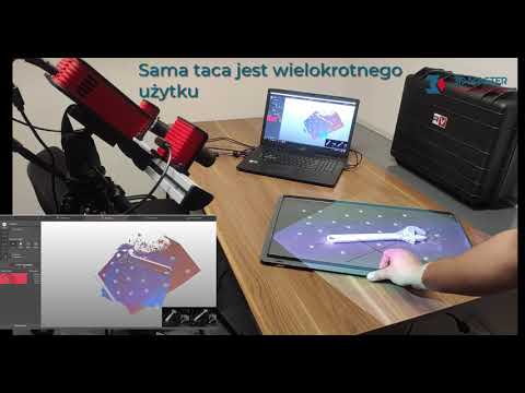 It is possible to scan deep areas of an object using a triangulation angle of 10°. All Solutionix scanners are calibrated on site, unlike devices from other manufacturers, which must be sent to a service center or to the factory (Fig. 1). nine0003
Fig. 1
Solutionix's product range includes eight 3D scanners that vary in features and price. For high-precision scanning of objects of various sizes, as well as reverse engineering and quality control, Solutionix offers Rexcan 3D scanners of the third (314, 320) and fourth (414, 420, 450, 480) series. The series differ in the light sources used: in Rexcan3 these are halogen lamps, and in Rexcan4 they are LEDs. The models are equipped with cameras with different resolutions, which directly affects the scanning accuracy (Fig. 2). nine0003
To scan small objects such as jewelry, Solutionix designers created the Rexcan DS2 scanner. It allows you to scan small-sized and rich objects with high accuracy. More recently, the new Rexcan CS+ model has been released, designed for scanning small and medium objects.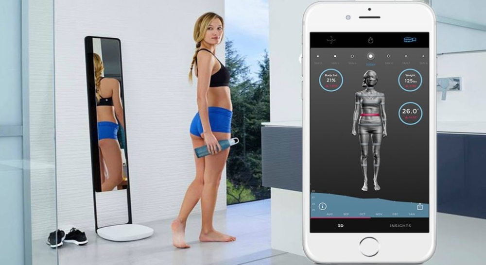 The scanning process in CS+ is fully automated, which allows you to scan the entire object with the click of a single button. The new scanner combines excellent quality and affordable price. nine0003
Fig. 2
Geomagic software has been developed to convert data obtained from 3D scanning of objects and subsequently work with the created 3D models in a wide variety of applications. Geomagic Studio, Geomagic Qualify and Geomagic Wrap software products are used all over the world. Specialists highly appreciate the advantages of these programs: ease of learning and operation, intuitive interface, high speed. Well, first of all, the fact that these programs can reduce the time to bring products to market and significantly improve their quality. nine0003
Brian Coombs Design used a Rexcan 420 3D scanner with Geomagic Studio software (the leading software for converting 3D scans to high-precision polygonal and native CAD models for reverse engineering, product design, and rapid prototyping) to solve layout problems for a design project. recreating the classic Ford GT40 sports car (Figures 3 and 4).
Fig. 3
Fig. 4
Speed is an integral part of Brian Coombs' life. He leads the team of engineers responsible for the mechanical and suspension design of the Bloodhound SSC, a British project for a jet-propelled vehicle. This car is designed to hold the British world land speed record (1610 km/h).
Brian Coombs, however, does not seem to be in the category of a hard and demanding task, as he spends his spare time at his home in Ireland recreating a replica of the classic Ford GT40 sports car. nine0003
GT40 with a modified 5-litre V8 engine delivers impressive power. Unfortunately, in an old copy of the GT40 that Coombs bought as an assembly kit a few years ago, the mechanisms (in particular the gearbox) may not be able to withstand such a load.
“The gearbox for this car is very expensive,” says Coombs. “So while restoring the car, I decided to build my own box using parts I had left over from an old Reynard Indy race car. ” nine0003
With extensive motorsport design experience (as evidenced by many years of experience with several racing teams, including the Formula 1 racing team Red Bull), Brian Coombs has the skills to take on the task, plus the knowledge with modern CAD/CAM technologies. So instead of traditional manual methods, Coombs used 3D CAD (Siemens NX) to create a digital 3D CAD model of the car from which some new parts could be redesigned and manufactured. nine0003
However, even with this in mind, designing a gearbox is a tricky business. When creating it from existing components, it is necessary to ensure that, installed in the appropriate crankcase, it fits into the free space under the hood, does not touch other parts and is correctly positioned in relation to them. Of course, it would be possible to build a physical model, manually install it in place and make the necessary measurements, but this would take a lot of time, which Coombs just did not have. nine0003
Nevertheless, an optimal solution has been found. The gearbox housing was scanned with a Rexcan 420 3D scanner and then an accurate digital 3D model suitable for layout purposes in a CAD system was created from the obtained data using the Geomagic Studio software.
3Dscan
When 3Dscanning, Brian Coombs again encountered speed, but in a slightly different aspect. As already mentioned, to obtain the shape of the gearbox housing, a Rexcan 420 3D scanner was used, which has two CCD cameras with a resolution of 2 megapixels (the Solutionix range of 3D scanners also includes scanners with a resolution of 1.4; 5.0; 8.0 megapixels) and provides acquisition of millions of points per second with an accuracy of ±20 microns. nine0003
The scanner was used in conjunction with the Solutionix automatic turntable for workpieces up to 70 kg. After installing the crankcase on the turntable, the scanner was set to scan from above at an angle of 45°. Using the Solutionix ezScan software, guiding and coordinating the turntable movements, the top half of the crankcase was automatically scanned in increments of 10° of turntable rotation.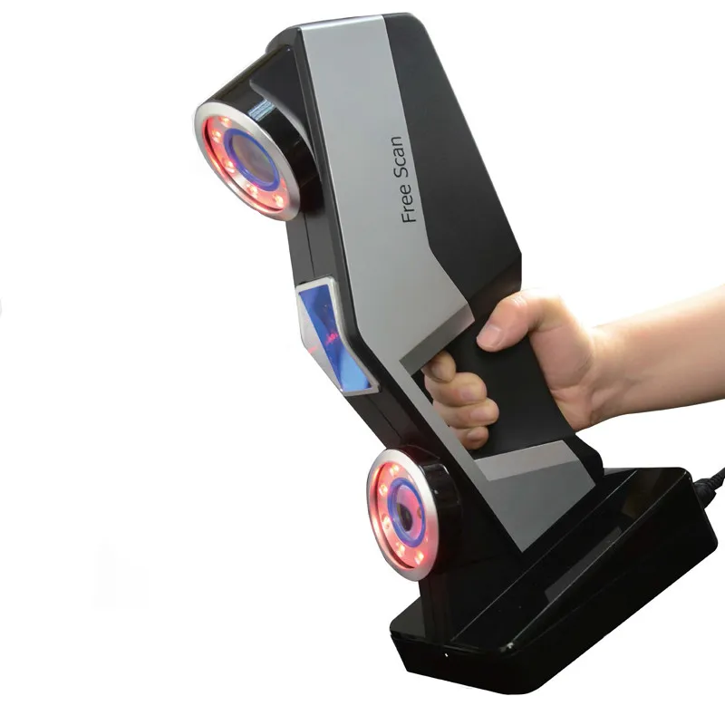 The crankcase was then inverted and the process repeated to scan the bottom half. nine0003
72 individual scans were acquired in about an hour. Using the Solutionix ezScan software, these scans were automatically stitched together to create a single polygonal 3D model of the gearbox housing from the point cloud. And although the combined model included only a fifth of the approximately 50 million polygons obtained by scanning, this turned out to be quite enough. To speed up the subsequent data processing, the model was simplified, as a result of which the number of polygons on flat surfaces was reduced, while on curved surfaces it was saved. This made it possible to reduce the number of polygons to approximately one million without compromising the accuracy of the model. nine0003
3D surface model
The next step was to convert the polygonal model into an accurate digital 3D surface model usable in a CAD system. To do this, the model was exported from the Solutionix scanning system to the Geomagic Studio software.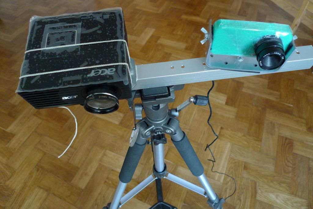 As we have already mentioned, this software is used to convert data obtained from 3D scanning of material objects into digital 3D models, suitable for subsequent use in a wide variety of applications - from the archiving of archaeological finds and works of art to engineering analysis, product development in accordance with specific customer requirements. and rapid prototyping. nine0003
First of all, it was necessary, using the standard tools of Geomagic Studio, to restore the polygonal model by filling in the "holes" in those places where scanning failed to completely obtain data on certain parts of the crankcase. As a result of this process, which took no more than ten minutes, a single, completely closed polygonal 3D model was obtained (Fig. 5).
Fig. 5
Program function Create Features was then applied ( Create Features ) for selecting and identifying simple geometric features such as cylinders, holes and planes on the model that can be directly transferred to the CAD system as parametric objects.
The final step was to use the AutoSurface command to convert a polygonal model including geometry elements to a NURBS (Non-Uniform Rational Spline) based surface model. This automatic process is quite simple, takes just two clicks and takes about two minutes. Next, function 9 was called0061 3D Compare ( Compare 3D ), designed to compare polygonal and surface models in order to confirm the geometric integrity of the final surface model (Fig. 6).
Fig. 6
After that, the final model was ready to be exported to the CAD system in STEP (*.stp) format, where it can be used as a separate solid model inside the 3D CAD model of the car chassis, sub-frame and suspension. This ensures that when it comes time to install a new gearbox, it will snap into place correctly, in perfect alignment with the other parts (fig. 7). nine0003
Fig. 7
Need for Speed
The entire process of scanning the gearbox housing and creating an accurate 3D digital surface model of it took approximately two hours.
This is what Brian Coombs has to say about this: “I have too little free time for my GT40 restoration project, and the almost automatic scanning process using the Solutionix scanner and turntable, combined with the automatic processing of scan data made possible by Solutionix ezScan and software for processing polygonal models and engineering analysis Geomagic Studio, saved me a lot of time. B to Most operations are performed with one or two mouse clicks.
However, speed in this case is not at all a compromise at the expense of quality.
“While it took only two hours to create a digital 3D model of the gearbox housing, which is impressive in itself, I was impressed with the resolution and accuracy of the original scan data, as well as the quality of the final 3D surface model,” notes Coombs. “Now I am absolutely sure that what I designed in the virtual world will be installed on a real car without any problems.” nine0114
The most accurate 3D scanner was created in Vyshneve.
 US jewelers in line
 Ukrainian inventor Leonid Nazarenko and his son Denis create a high-precision 3D scanner for jewelers. It has no analogues in the world in terms of price and quality
The story of two inventors began about four years ago when they wanted to get high-precision 3D models of small objects, such as coins or figurines. But faced with the fact that the laser scanners available on the market, firstly, are very expensive, and secondly, their accuracy left much to be desired. nine0003
The very idea of the scanner was born when Denis Nazarenko was trying to make a model of the statue of Manjushri. “But scanners capable of capturing the smallest details of a model cost at least 17,000 euros and were out of reach for a small company. So we decided to create our own,” the Kickstarter presentation reads.
Who are Nazarenko
In a small office in the town of Vyshneve near Kyiv, father and son set about experimenting. The background allowed them to use deep knowledge from completely different engineering fields. nine0003
Leonid Nazarenko began his career at the Antonov plant, which built the world's largest An-225 aircraft. He created models of aircraft from childhood, and then taught schoolchildren to do the same. Leonid had a good understanding of metalworking and a wide range of knowledge in engineering disciplines.
Denis Nazarenko won various competitions in mathematics, physics and computer science. He has been working on software development for many years. And his most famous project is Start Menu X, a convenient alternative to the Windows Start menu, which has been used by many people around the world. nine0003
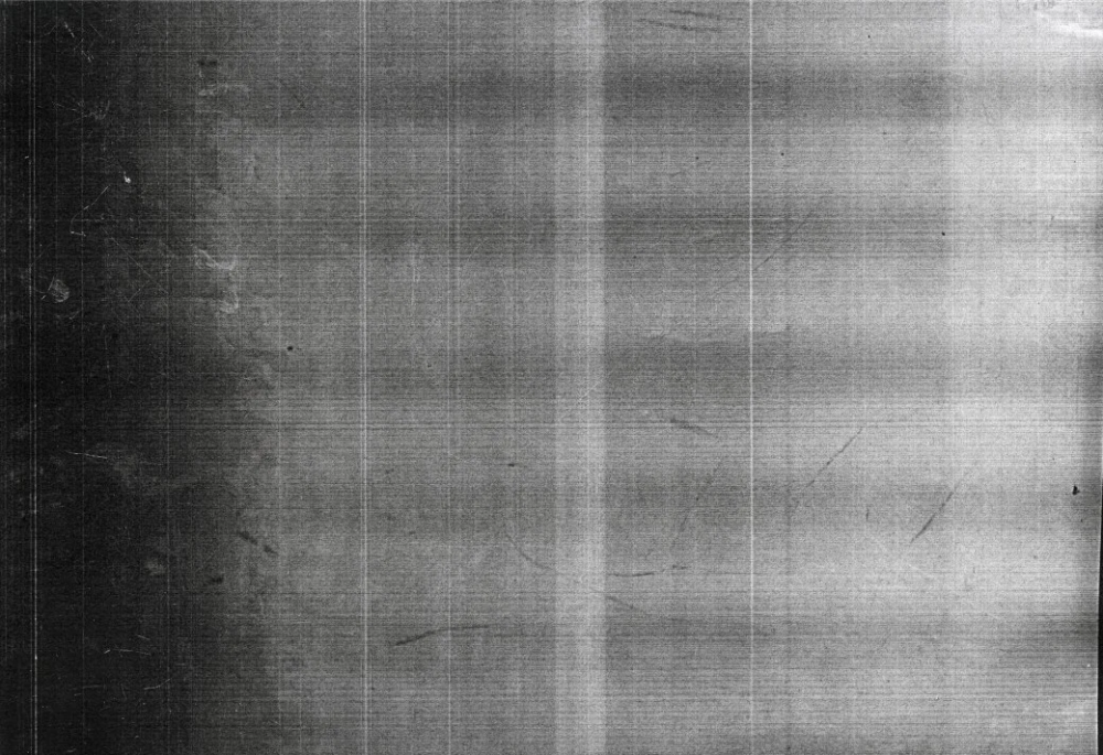
LED vs Laser
As two engineers found out, a laser projector creates a lot of scanning noise, which is detrimental to the quality of the 3D copy. And he has a worthy alternative. The light-emitting diode (LED) beam in combination with good lenses made it possible to achieve noticeably better results.
'' This photo shows how much noise the laser beam has compared to the LED beam:
''
Another bonus. This technology does not require expensive projectors and cameras. nine0003
Entrepreneurs decided to take their idea to Kickstarter through a partner who lived in Canada. Last spring, they raised over $22,000 to produce their first model, the D3D-s desktop 3D scanner.
According to Denis Nazarenko, who was contacted by the journalist of Liga.Tech , together with his father, they collected and delivered about 10 scanners to investors who supported them with money on the crowdfunding site during the year. A few pieces are still being finalized.
Fashion for second rings
According to Nazarenko, during this time they managed to find the exact niche for their devices - the American jewelry market. According to him, the tradition of wearing so-called shadow wedding bands is widespread in the States. These are additional rings that spouses order in addition to engagement rings, for example, for a wedding anniversary, and then both of them are worn on the same finger.
In such cases, jewelers need to scan the engagement ring and actually make a replica of it. nine0003
Ukrainian inventors began to receive requests from jewelers and dentists. Such niche demand prompted Nazar and Denis to launch their second Kickstarter campaign - a 3D scanner specifically for jewelers. They launched it a week ago, at the end of June 2019, and have already collected the requested amount - $13,600 out of $15,000. The project was supported by eight people who wanted to get a jewelry scanner. The first supporters will get it for $4000-6000. And in retail, the device will already cost $8,000
"The D3D-s scanner is suitable for both self-employed jewelers and professional teams with experience using ultra-expensive scanners," the developers note in the project description.
According to Denis Nazarenko, a 5 megapixel camera is installed in the scanner, which is much cheaper than a less accurate 1.2 megapixel camera designed for laser scanners.
Another innovation is mobility. The scanner also has six directions for movement. This allows you to scan figures of any complexity with a light beam. Scanning is fully automatic. You just need to specify the size and click the button. nine0003
When we created the desktop scanner, we wanted to achieve a resolution that would allow us to scan a coin. As a result, adapting the scanner to the needs of jewelers was not a problem. We have added another axis of rotation and reduced the size of the scanner. We've also upgraded the optics and camera, as jewelers don't need color scanning. We also installed high-precision motors," the developers of the device say.
The price of the device is much cheaper than its counterparts.Scan 350 - will cost almost $15,000. At the same time, even the most expensive laser models (for $50,000) cannot provide such a distance between points as the Ukrainian development - 0.010 mm.
Denis and Leonid can now produce 1-2 scanners per month in their office near Kyiv. They work together.