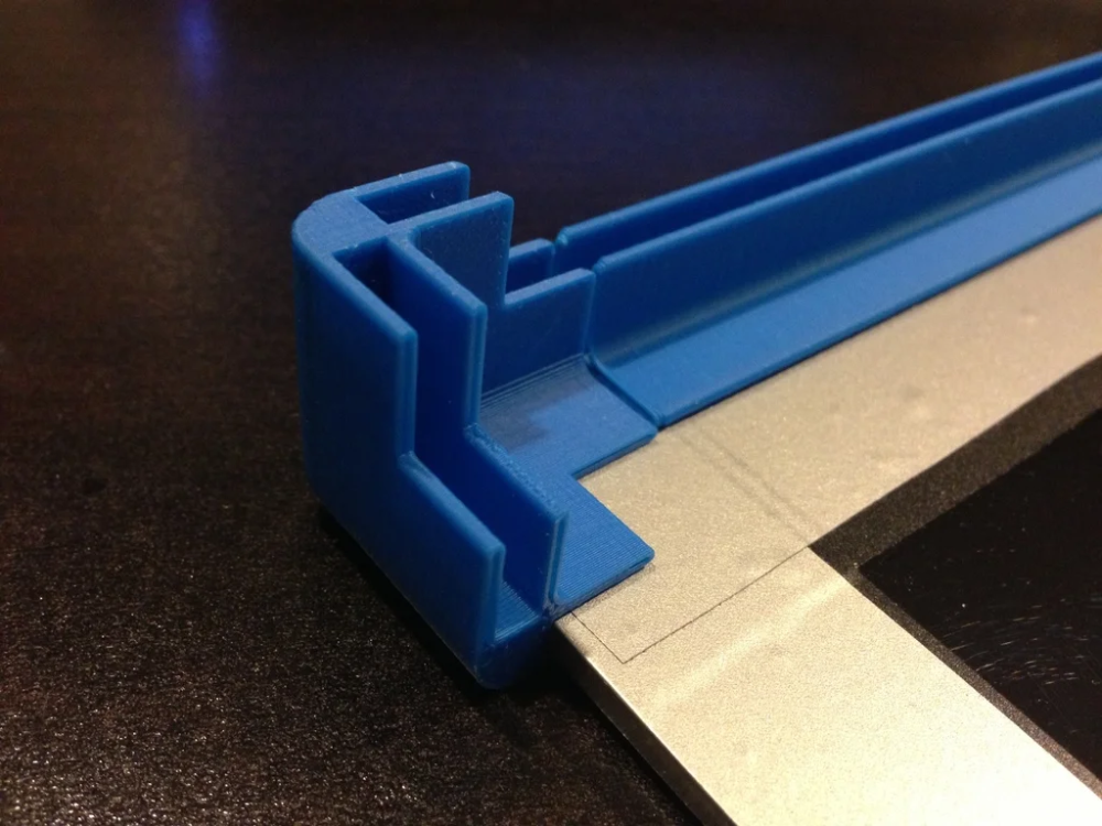
3D printer corner
7 Ways How to Fix Rough Edges/Corners on Your 3D Prints – 3D Printerly
Some people have experienced rough edges or corners on their 3D prints which ruin the print quality.
You should increase your print temperature, slow down your print
There are some effective ways to fix this issue which will be described in detail within this article so keep on reading to get the solution fixed once and for all.
Why Do My 3D Prints Have Rough Edges/Corners?
The problem of having rough corners is so frustrating because it can occur at any time during the print and when you will get your finished print it will not be of the quality you expected.
This problem can be so bad sometimes that you will not have any other options except to end up your prints into the trash.
Most of the time this issue is caused because of the overheat and the type of filament you are using because some of the filaments are good in order to stick to the bed and cool down quickly.
It is necessary to take a clear look at the problem because without a deep understanding of the problem you will not be able to fix this problem efficiently.
There are many reasons that cause this problem to occur but you don’t have to worry because you can fix this problem by taking care of some factors.
The major reasons behind the 3D prints having rough edges or corners include:
- Printing at High Temperatures
- Printing the Object too Fast
- Z Offset and Print Bed is Not Adjusted Accurately
- Printing Very Thin Objects
- Using a Filament that is More Prone to this Problem
- Inefficient Cooling of Material
- Inconsistent Operating Temperature
How to Fix Rough Edges/Corners on 3D Prints?
With the increasing popularity of 3D printing, the manufacturers are improving their products and technologies to provide their customers with the best printing experience.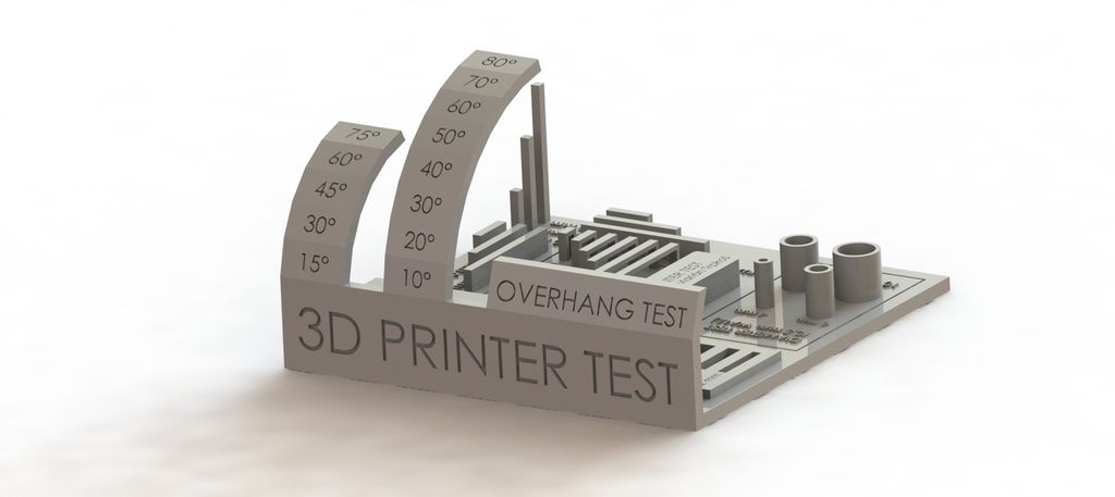
To have a better experience, experts have suggested some tips to avoid the rough edges problem and also some solutions that can help you get rid of the problem completely.
It is recommended to take the necessary steps to avoid this problem before printing an object because in this way you will be able to prevent your prints from rough edges.
If you are still getting prints with rough edges even if you think you are doing your best then you should consider the following solutions to get the best of 3D printings.
Let’s talk about the most common and the easiest solutions that can help you out from the problem.
1. Consider Printing at Lower Temperature
Overheating is one of the most common causes behind the 3D prints with rough edges. This is the first thing you should consider whenever you face such a problem.
When the print is being heated at a high temperature constantly, there are huge changes that the corners of the object will meltdown and the resultant print will have rough or lifted edges.
- The first thing you should do is to lower down the printing temperature to avoid this problem.
- It is recommended to lower down the temperature step by step and set the temperature where you see that the 3D printer is printing objects with perfect corners.
- Lower down the temperature within the range that it is enough for the filament to melt because too low heat will make it difficult for the filament to extrude from the nozzle.
2. Decrease Printing Speed
Printing at a high speed can cause the problem of rough edges and corners just because the new heated filament layer on the previous layer will be extruded in very little time.
The previous layer will not have the required time to cool down properly because the new heated filament will be extruded on it.
This fact will cause the layer to remain soft and with the increasing layers, it will begin to bend creating rough edges and corners.
This can also ruin the whole print if the layers in the bottom of the print slip off completely.
- Decrease the speed of the printing at which the nozzle is moving because it will help the layers to cool down and become solid before the next layer.
- It is recommended to print at a slightly slower speed at initiation because the bottom should be solid enough to bear the weight of the object.
3. Make Sure the Print Bed and Z-Offset is Well Scaled
This could be one of the basic reasons for rough edges. The wrong or imperfect calibration of the z offset and print bed cause major printing issues and the rough edges is one of them.
If they are not calibrated correctly the layers will not be aligned and a bit of difference will lead to the prints of poor quality especially in terms of clearness and sharp edges.
- Make sure that the print bed is leveled perfectly and adjust the z offset at the right height.
- The height of the nozzle should be adjusted in a way that it cannot collide with the print and it should not be too high from the object being printed.
4. Try to Print Thicker Objects
There are some prints that have very thin parts such as the legs of a little chair, these thin parts can become a reason for rough edges to occur because they are more prone to rough edges.
- Try to print the parts thick enough that they can be printed efficiently without ruining the edges.
- If you have to print thin objects then you should provide them enough time so that they become totally solid.
- There are also amazing features in most of the printers that automatically slow down the speed when you are printing thin or small objects.
5. Use Filaments That are Not Very Prone to this Problem
The type of filament you are using also can contribute to the reason for having a print with rough edges.
Filament such as ABS are more prone to have rough edges or corners as compared to PLA filament.
Using ABS filament will require a high temperature because it requires higher heat to melt and extrude. That’s why you hear that ABS is a lot harder to print than PLA, because it gives temperature-related problems, which cause warping or curling.
Those print imperfections contribute to those rough corners and edges that you see in 3D prints.
- Try to use filament material that is less prone to the problem and can work properly even at low temperatures.
- Use a material that has better sticking properties.
- Use filaments that can cool down and become solid quickly.
6. Implementing a Better Cooling System
When your parts aren’t cooling down properly, they are still in that liquid-type of form which isn’t good for creating smooth prints.
After the next layer gets extruded, it won’t properly adhere to the previous layer and can easily displace the material. When this happens, you get those rough corners/edges as a result, so we need to cool our prints better.
In order to get better cooling we should:
- Use a fan duct which directs cool air towards the 3D print
- Get a stronger fan which is proven to produce great cooling
- Increase your fan speed in your slicer settings
7. Use an Enclosure to Control Operating Temperature
Related to many points above, this is mainly a temperature issue, so you want to control the operating and printing temperature as much as possible to correct this.
- Get yourself an after-market enclosure or build a DIY one
- Make sure it keeps the heat in by keeping it airtight and using a thermometer
How to Fix Bulging Corners on 3D Prints
To fix bulging corners on your 3D prints, you want to try reducing your Wall Speed in your slicer, since when corners are printed, the rate of extrusion is increased due to your printer slowing down on these sections. 30-40mm/s is a safe speed to fix bulging corners.
This is mostly to do with the build up of pressure in the nozzle while using higher speeds.
There is a consistent flow rate that is happening with longer lines of extrusion, so when the print head gets to the corner, the slowdown in speed doesn’t provide a slowdown in the level of pressure in the nozzle, leading to more material extruded in the corners.
You can get the best dimensional accuracy for your 3D prints by reducing your print speed.
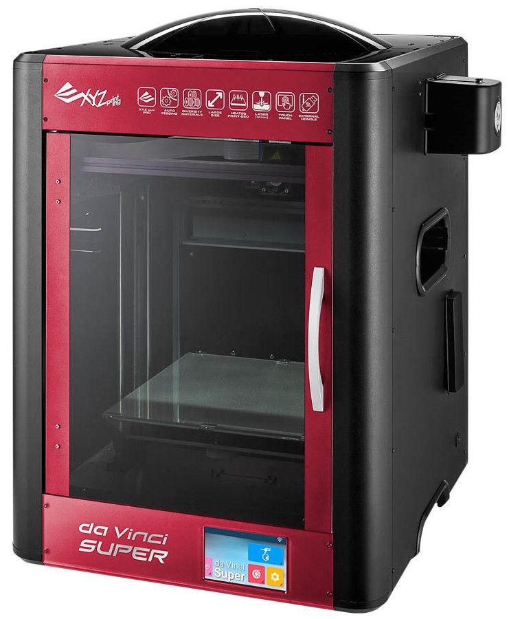
Reliable, Industrial Grade 3D Printer
Shape accuracy is a critical criterion for accuracy and refers to the extent of how well the surface shape of the fabricated part matches the design. Common surface shapes include round, flat, column, conical, linear etc. This blog discusses how to improve the 3D printing shape accuracy of a sharp corner using ideaMaker.
Note: To be precise, this blog entry only discusses accuracy applied to a Cartesian FFF printer and ideaMaker.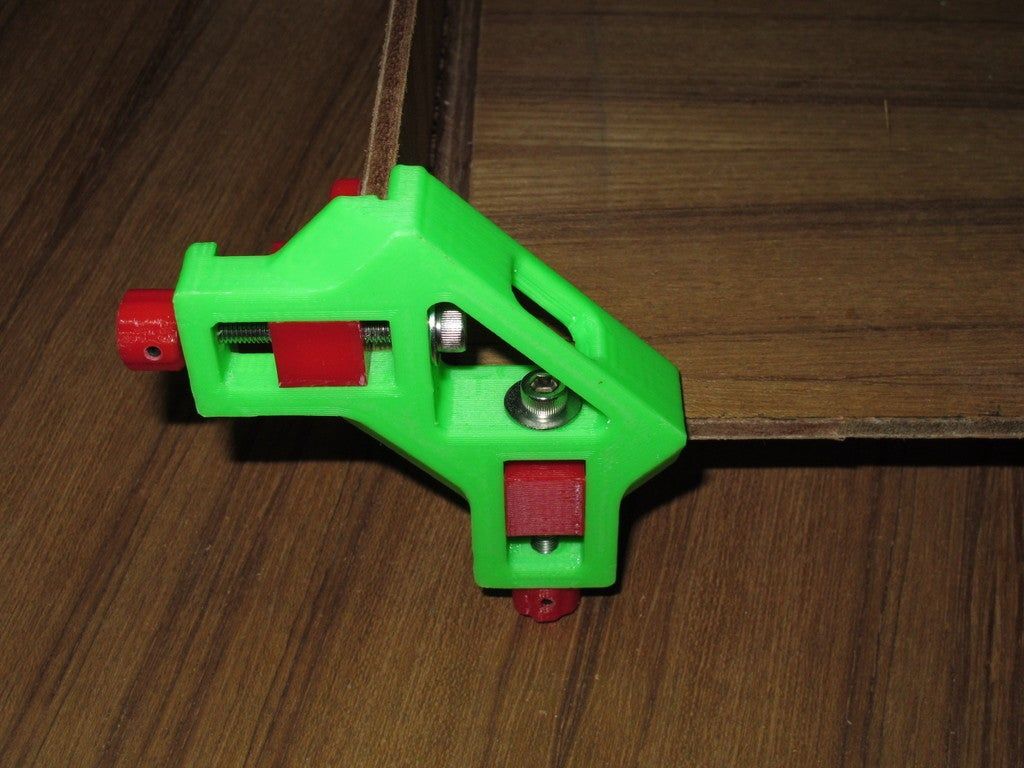
A rectangular specimen printed for reference
Example of a Common Flaw: A Corner Bulge in the XY Direction
A sharp corner is formed by the encounter of two straight surfaces. A bulged angle is formed when the vertex where the surfaces meet bends towards the convergent point. The following comparison shows the difference between a bulged and a fine corner. The contour of a fine sharp corner is straight without visible bending. A bulged corner may cause a printed part to have poor assembly quality and an enlarged dimensional tolerance, resulting in printed parts not fitting correctly.
Bulged Corner (Left) vs. Fine Sharp Corner (Right)
Image Source: https://www.printedsolid.com/
Situation 1: A Bulged Corner at the Start and End Point
It is common practice for slicing software to define a corner vertex as a start or end point on each layer. A bulged corner forms when over-extrusion occurs at a start point or end point during printing.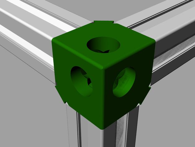 When there is too much pressure applied or too much material melted at these points, the amount of filament extruded at these points will be more than the ideal amount along the vertex.
Image from https://reprap.org/
How to Fix with ideaMaker:
1. Increase the Amount of Retraction Material (Advanced Settings>Extruder>Retraction Material Amount)
This setting can reduce existing material in the nozzle at the start/end point. But a value that is too high may result in under-extrusion and a gap in the corner.
2. Increase the Value of Gcode M572 (Advanced Setting>GCode>Start GCode)
Gcode M572 refers to the advance pressure feeding compensation rate based on speed. In case of normal printing, when printer printing speed increases, the printer feeding rate increases accordingly. When printing speed decreases, the feeding rate also decreases. Increasing the value of M572 heightens the feeding rate reduction when printing speed down at the end point of the printing loop before next layer.
Situation 2: Corners without Start and End Point
Sometimes a corner is irregular, and can also be known as ghosting, ringing, echoing or ripping, even if it is not defined as a start or end point. This is usually caused by machine vibrations during the printing of the corner area. When the extruder is moving fast along a certain direction and has a sudden speed change, it will generate lots of force, which has to be absorbed by the printer. A printer with more weight and a stiffer frame can absorb this force better, resulting in less vibration.
Image source: https://3dprinterly.com/
How to Fix with ideaMaker:
1. Lowering the Inner and Outer Shell Print Speed (Advanced Settings>Speed)
In ideaMaker, loops forming contours of each layer are defined as the outer shell and inner shell. Therefore, lowering print speed value for these two structures can reduce existing vibration when printing corners.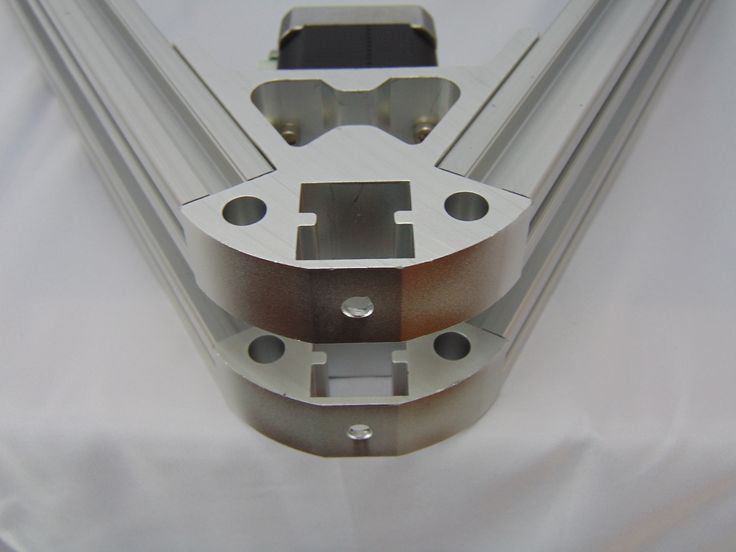
2. Lowering the Acceleration Speed ( Advanced Settings>Advanced)
Lowering the acceleration speed of the inner and outer shell can also reduce vibration when printing corners. Lower acceleration speed brings less shaking when the speed begins to change. Users need to enable the Acceleration option in ideaMaker first.
3. Reduce the Jerk Speed (Advanced Settings>Advanced)
Jerk speed refers to the instantaneous speed to start printing or the minimum speed required before printing stops or changes direction. When printing a sharp corner, the extruder movement direction will change significantly. The extruder has to suddenly drop its speed to zero along the original direction at the turning point. The jerk speed refers to the instantaneous speed along the original direction at that moment. A larger jerk speed means the printer absorbs more force when the extruders change direction. However, if this value is too low, the printing duration will be significantly extended and result in flaws in the final print.
Mounting bracket for 3D printer 18 x 40 x 40 mm (#12)
Home > 3D PRINTERS, CONSUMABLES AND ACCESSORIES > Components for 3D printers and CNC > Mounting bracket for 3D printer 18 x 40 x 40 mm (#12)
CATEGORIES
PRODUCT DETAILS
- 3D PRINTERS, CONSUMABLES AND ACCESSORIES
- ACOUSTIC COMPONENTS
- ANTENNAS
- AEROSOLS, TECHNICAL
- FANS
- ALL FOR SOLDERING: SOLDERING IRONS
- EVERYTHING FOR SOLDERING: SOLDERING STATIONS AND BATHS
- ALL FOR SOLDERING: SOLDERS
- ALL FOR SOLDERING: SOLDERING FLUXES
- ALL FOR SOLDERING: AUXILIARY TOOLS
- SOLDERING ALL: PCB MATERIALS
- ALL FOR SOLDERING: OILS, LUBRICANTS AND PROTECTIVE COATINGS
- SENSORS
- DIODES
- MEASURING INSTRUMENTS
- TOOL
- POWER SUPPLIES
- CABLE PRODUCTS
- CABLE ACCESSORIES
- CAPROLONE AND POLYACETAL
- TERMINALS
- TERMINALS
- SWITCHING
- CAPACITORS
- FASTENER *
- METAL ALUMINUM
- METAL BRONZE, NICKEL AND MOLYBDENUM nine0009 METAL ALLOY
- METAL BRASS
- METAL COPPER
- NICKEL SILBER AND MELCHIOR METAL
- METAL STAINLESS AND STRUCTURAL STEEL
- NICHROME METAL, MANGANIN, CONSTANTAN AND PERMALLOY
- METAL LEAD, TIN AND ZINC
- METAL TITANIUM
- CHIP
- OPTOELECTRONIC DEVICES
- LIGHTING AND DISPLAY
- COOLERS nine0009 GOOT SOLDERING EQUIPMENT
- BEARINGS
- MOUNTING WIRE
- WINDING WIRE
- CONNECTORS
- CONSUMABLES
- RESISTORS
- RESONATORS AND FILTERS
- SILICONE
- RELAY
- WAREHOUSE EQUIPMENT
- COUNTERS
- TEXTOLITE AND GLASS TEXTOLITE
- THERMAL PASTES AND HEAT CONDUCTING MATERIALS
- THYRISTORS
- TRANSISTORS
- TRANSFORMERS and CHOCKS
- INSTALLATION PRODUCTS
- PROTECTION DEVICES
- FERRITES and MAGNETS
- PANEL INSTRUMENTS
- VACUUM EQUIPMENT
- ELECTRIC MOTORS
- ELECTRONIC DEVICES
- ELECTRICAL, HEAT-RESISTANT AND DIELECTRIC MATERIALS
Mounting bracket for 3D printer 18 x 40 x 40 mm. Figure #12 nine0003
Material - aluminum alloy
Hole diameter - 5 mm
Height - 40 mm
Length - 40 mm
Width - 18 mm
Manufacturer - China
available
Linear bearing LM8UU for 10 mm shaft
250.00 RUB
Buy
in stock
Intermediate support SK16 for 16 mm shaft (15)
320.00 RUB
Buy
in stock
SCS8UU linear bearing assembly for 8 mm shaft (#8)
300.00 RUB
Buy
in stock
Mounting bracket for 3D printer 20 x 28 x 28 mm (#2)
50.00 RUB nine0003
Buy
available
SCS12UU linear bearing assembly for 12 mm shaft (#9)
350.00 RUB
Buy
available
Intermediate support SK25 for 25 mm shaft
500.00 RUB
Buy
available
Intermediate support SK8 for 8 mm shaft (3)
130.00 RUB
Buy
in stock
Mounting bracket for 3D printer 35 x 34 x 34 mm (#6)
100. 00 RUB
Buy
in stock
Mounting bracket for 3D printer 29 x 34 x 34 mm (#5)
100.00 RUB nine0003
Buy
in stock
SCV8UU linear bearing assembly for 8 mm shaft
200.00 RUB
Buy
Mounting bracket for 3D printer 20 x 28 x 28 mm (#2)
Home > 3D PRINTERS, CONSUMABLES AND ACCESSORIES > Components for 3D printers and CNC > Mounting bracket for 3D printer 20 x 28 x 28 mm (#2) nine0003
CATEGORIES
PRODUCT DETAILS
- 3D PRINTERS, CONSUMABLES AND ACCESSORIES
- ACOUSTIC COMPONENTS
- ANTENNAS
- AEROSOLS, TECHNICAL
- FANS
- ALL FOR SOLDERING: SOLDERING IRONS
- EVERYTHING FOR SOLDERING: SOLDERING STATIONS AND BATHS
- ALL FOR SOLDERING: SOLDERS
- ALL FOR SOLDERING: SOLDERING FLUXES
- ALL FOR SOLDERING AUXILIARY TOOLS
- SOLDERING ALL: PCB MATERIALS
- ALL FOR SOLDERING: OILS, LUBRICANTS AND PROTECTIVE COATINGS
- SENSORS
- DIODES
- MEASURING INSTRUMENTS
- TOOL
- POWER SUPPLIES
- CABLE PRODUCTS
- CABLE ACCESSORIES
- CAPROLONE AND POLYACETAL
- TERMINALS
- TERMINALS nine0009 SWITCHING
- CAPACITORS
- FASTENER *
- METAL ALUMINUM
- METAL BRONZE, NICKEL AND MOLYBDENUM
- METAL ALLOY
- METAL BRASS
- METAL COPPER
- NICKEL SILBER AND MELCHIOR METAL
- METAL STAINLESS AND STRUCTURAL STEEL
- NICHROME METAL, MANGANIN, CONSTANTAN AND PERMALLOY
- METAL LEAD, TIN AND ZINC nine0009 METAL TITANIUM
- CHIP
- OPTOELECTRONIC DEVICES
- LIGHTING AND DISPLAY
- COOLERS
- GOOT SOLDERING EQUIPMENT
- BEARINGS
- MOUNTING WIRE
- WINDING WIRE
- CONNECTORS
- CONSUMABLES
- RESISTORS
- RESONATORS AND FILTERS
- SILICONE nine0009 RELAY
- WAREHOUSE EQUIPMENT
- COUNTERS
- TEXTOLITE AND GLASS TEXTOLITE
- THERMAL PASTIES AND HEAT CONDUCTING MATERIALS
- THYRISTORS
- TRANSISTORS
- TRANSFORMERS and CHOCKS
- INSTALLATION PRODUCTS
- PROTECTION DEVICES
- FERRITES and MAGNETS
- PANEL INSTRUMENTS
- VACUUM INSTRUMENTS
- ELECTRIC MOTORS
- ELECTRONIC DEVICES
- ELECTRICAL, HEAT-RESISTANT AND DIELECTRIC MATERIALS
Mounting bracket for 3D printer 20 x 28 x 28 mm. Figure #2
Material - aluminum alloy
Hole diameter - 6 mm
Height - 28 mm
Length - 28 mm
Width - 20 mm nine0003
Manufacturer - China
available
Linear bearing LM8UU for 12 mm shaft
300.00 RUB
Buy
in stock
Mounting bracket for 3D printer 30 x 58 x 58 mm (#4)
200.00 RUB
Buy
available
Intermediate support SK20 for 20 mm shaft (16)
400.00 RUB
Buy
in stock
Mounting bracket for 3D printer 17 x 20 x 20 mm (#1)
35.00 RUB
Buy
in stock
Retaining ring for LM6 linear bearing, 10 pcs
120.00 RUB nine0003
Buy
available
Linear bearing LM8UU for 10 mm shaft
250.00 RUB
Buy
in stock
SCS8UU linear bearing assembly for 8 mm shaft (#8)
300.00 RUB
Buy
in stock
Retaining ring for linear bearing LM8, 10 pcs
120.