3D scanner texture
How to Easily Master Textures With Artec 3D Scanners
Toggle Nav
Menu
Account
Settings
Currency
USD - US Dollar
- CAD - Canadian Dollar
Posted in: 3D Scanning
by Matthew Fisher
August 31, 2022 Edited August 31, 2022
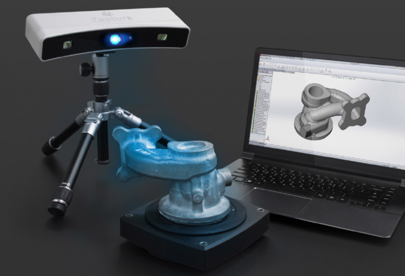
Aside from their ability to capture complex geometry without any targets, one of the greatest features of handheld Artec 3D scanners is their ability to simultaneously capture color.
Sometimes refered to as texture, color is incredibly important to create lifelike renders and identify key locations on parts. Normally, texture has to be captured seperately and then projected onto a mesh – a time-consuming process and impossible if any part of the object moves between the two different captures. Since the handheld scanners capture both geometry and texture at the same time, there isn’t any issue matching the color to the exact position it should be.
Below is an example of a tapestry captured using the Artec Leo and processed to one million triangles. The mesh, triangles, and raw texture data provides a high-quality mesh with matching full color spectrum.
How to Add Texture Effectively
With our scan captured, we can process and apply the texture to the mesh via the texturing tool. With this tool, we have various options to adjust how the color is applied – such as which scans the color will be pulled from, normalizing the textures, and most importantly, the quality of the color being applied.
The output texture size affects the overall quality of the texture – the lower setting generates higher pixilation but has the smallest file size. This texture doesn’t have any extra information beyond color, often referred to as the Albedo layer of a material. Once exported, you can use this color layer within a rendering program and adjust the lighting and overall material of the mesh while keeping true to object colors. This texturing process can also help with reverse engineering if the product has key locations marked and outlined with chalk or paint.
Below is a list of the outputted textures based on the size used in the options:
While there is a significant difference in quality between 512x512 and 8196x8196, there is almost no difference between the 8196x8196 and 16384x16384. Additionally, the file size is almost tripled between 8K and 16K, adding to processing and exporting times.
When applying the texture, keep the end use of this mesh in mind. If it’s going to be a single object, rendering the 16K texture may be useful, but in a scene of multiple items, 4K may be enough if the object is in the background.
Adjusting Texture Settings with Glare Reduction
Another option that can improve the quality of the color of the mesh is glare reduction. This will normalize the entire scan to reduce areas of high contrast from the scanners light. The higher this setting is, however, the more muted the color becomes. Keeping the setting at 3-4 is recommended because of this. With reduced glare enabled, we can also use the reduce background information, which helps with competing surfaces in scan data that may cause overlapping texture issues.
Once the texture is applied using the export option, which combines the color maps all into a single file, we can export the mesh as a .obj or .wrl so the color can be remapped to our mesh in another program. From here, we can adjust the material of the mesh or color map within photo editing software to create lifelike renders.
For more information on 3D scanners or if you have any questions, contact us at Hawk Ridge Systems today.
August 31, 2022
Did you like this post?
Related posts
Related Products
Comments
Please login to comment.
Don't have an account?
Sign Up for free
Recent posts
Email address is required to login
Laser Texture and Surface Scanner, Microtexture and Macrotexture
Ames Laser Texture Scanner Correlates to Sand Patch TestCP2 Center News, December 2013 Newsletter
Caltrans Using Fog and Rejuvenating Seals on State Highways for Preventative Maintenance
By Peter Vacura, Caltrans; Lerose Lane and Ding Cheng, CP2 Center
Caltrans completed another series of pilot fog seals projects during the 2013 construction season. Fog seals have required special permission from Caltrans Headquarters, since a moratorium was put in place in 1990s. This study was meant to re-establish best construction practices in an effort to lift the moratorium and allow use of fog seals on state contracts and it will also allow Caltrans the opportunity to develop new comprehensive specifications and guidelines for reviving the standard usage of fog seals for preventative maintenance, at a low cost.
In 2013, District 2 placed four pilot projects on Interstate 5. District 3 had two pilot projects, including one in Colusa County on SR 20, one in Glenn County on SR 45. District 10 placed three pilot projects, two of which were located in Tuolumne County on SR 120, and one in Amador County on SR 104. Pavement types which were seal coated included gap-graded, open-graded, and one dense-graded pavement. Various application rates of the fog or rejuvenating seals were used with testing conducted by Caltrans and the CP2 Center to evaluate the immediate surface characteristics of the fog seals. The projects application rates varied from 0.07 to 0.14 gal/ yd2. Table 1 shows the 2013 project location list which includes construction dates and pavement types.
The CP2 Center evaluated several different test methods for measuring friction and used statistical correlation of the results for their comparison, with the objective of maintaining an adequate skid resistance after the fog seal treatments. There was only one project, on
SR 120 that had dense graded pavement. The Center is working to tie the macro-texture numbers to skid resistance, both with and without sanding.
For the 2013 projects, the Center used the sand patch test, ring test, and a new tool, the Laser Texture Scanner (LTS) for measuring pavement texture and friction. More skid testing was also done by Caltrans during 2013, using their ASTM E 274 skid trailer. This varied from the 2012 testing, where the Circular Texture Meter (CTM), the Dynamic Friction Testing (DFT) apparatus, and the British Pendulum was used on several of the projects.
The Center used the LTS on the three projects that were placed in August. The correlation between the LTS and the sand patch is shown in Figure 1. The linear trend line in the figure shows that there is a direct relationship between the LTS and the sand patch test and a strong statistical relationship.
The Ring Test was performed to determine optimum emulsion application rate for a 20 minute break time. Figure 2 shows the emulsion at four different application rates.
The Sand Patch Test, ASTM E965, was to determine macro-texture of pavement by spreading 25 ml. of glass beads into a circular shape and measuring the diameter of the circle. These beads are to pass a No. 60 sieve.
The Laser Texture Scanner (LTS) was used to scan and precisely measure the texture component of the pavement surface. Once a scan has been done, the scanner immediately calculates the Mean Profile Depth (MPD) and is capable of showing a visual of the scanned results as well as a numerical result. This meter is portable and light weight which allows the data to be easily collected and stored.
The ASTM skid trailer was used to measure the friction of paved surfaces with a fullsized automotive tire.
The test method used was ASTM E 274. The skid trailer utilizes a measurement that is representative of the steady-state frictional force on a locked test wheel as it is dragged over a wetted pavement surface under constant load and at a constant speed. During testing, the major frictional plane is parallel to the direction of travel and perpendicular to the pavement. The values are initially measured in inch-pounds and converted to a coefficient of friction to evaluate a pavement’s skid resistance. To evaluate the change in the pavement’s skid resistance, a test needs to be performed both prior to the treatment and after the treatment.
To illustrate the importance of macrotexture at high speed, the friction speed curve shown in Figure 5 was developed using the constants developed by University of California Pavement
Research Center (UCPRC).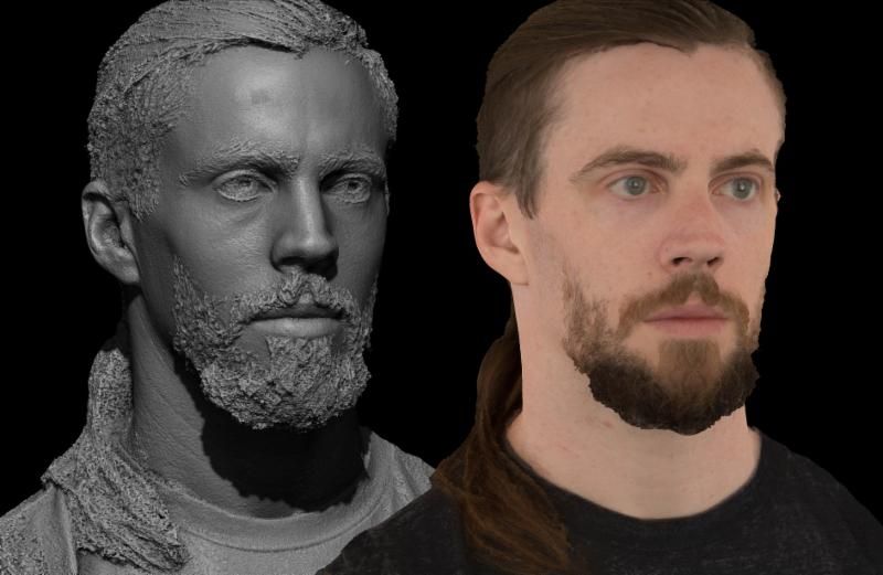 Figure 5 shows that the higher the macro texture, the flatter the friction-speed curve and higher the friction at high speed. For low macro texture surfaces, the friction dropped significantly at high speed. Therefore, minimum macro texture level should be provided to ensure the safety of vehicles under high speed and wet pavement conditions.
Based on the testing results of the 2012 and 2013 skid and texture measurement, the recommended minimum macro texture for Open graded and Gap Graded RHMA are 1.15 and 0.75 mm, respectively. These two macro texture values are corresponding to skid numbers that are greater or equal to SN40 of 30 for ASTM skid trailer test. The summary of test results for open-graded and gap-graded pavement is shown in Table 2.
Conclusions
The following are conclusions from the study:
- The field evaluation showed that fog or rejuvenating seal treatment sections performed better than the untreated or control sections.
 The treatment reduced the raveling and minimized other distresses.
- Generally, the macro texture decreased when the fog seal application was applied.
- The emulsion breaking times from the ring tests using fog or rejuvenating seals were highly dependent on the temperature, climate, type of fog seal material, application rate, and pavement type. The pavement pilot projects demonstrated a 15-20 minutes emulsion breaking time to be optimum.
- Generally, skid resistance of the pavement surfaces decreased after the fog seal was applied, but then increased on the projects that included sanding or texture sealing with a copper slag product.
- High macrotexture surfaces generally have higher high speed friction than low macrotexture surfaces for the same type of pavement. Macrotexture is a very important parameter for increasing speed constant and friction number of the international friction index.
- For the 2012 and 2013 pilot projects, the range of texture levels for open-graded asphalt were from 1.
 15 to over 2 mm. Generally, the skid numbers of these open-graded pavement pilot projects were higher than Caltrans’ recommended minimum skid number of 30.
- For the 2012 and 2013 pilot projects, the range of texture levels for gap-graded asphalt were from 0.75 to 1.38 mm. The skid numbers of these gap-graded pavement pilot projects were higher than Caltrans’ recommended minimum skid number of 30.
Recommendations
To account for varying textures and pavement types the following recommendations are:
- A ring test (similar to CT 345) should be run to determine the appropriate application rate for the fog seal. This test determines the rate that provides adequate coverage and also has break time approximately 15-20 minutes.
- Good results can be attained when the fog seal is placed at the pavement temperature above 50oF, ambient temperatures above 60oF, no anticipated precipitation for 3-5 days.
- The higher the macro texture levels, the less the risk for safety issue due to high speed skid loss.
 Based on both the 2012 and 2013 Caltrans pilot project studies, a macro texture of 1.15 mm for open graded mixes, and 0.75 mm for rubberized gap-graded mixes typically resulted in friction numbers above 0.30.
- Sand should be applied to ensure the initial friction is adequate right after treatment.
A project report for the fog seals will be completed by the Center, and the individual projects will be placed into the Center’s database for future tracking.
3D Scanning in Brief - Artec Studio 12 Documentation
Before you get started with the user manual, we would like to show you how easy 3D scanning can be. While this structured guide covers all aspects of Artec 3D scanners and software, it's a good idea to have a general diagram handy. This brief overview will help you get started without delay. But if you prefer to start with detailed and comprehensive information, skip this chapter. nine0003
Activation
The scanner comes with everything you need to get started, except for a personal computer. At a minimum, your computer must be running a 64-bit version of Windows 7 or 8 (version 10 is also supported). The more powerful the computer, the better. The most attention should be paid to RAM and video card (for details, see the FAQ page).
Warning
Do not connect the scanner to the computer yet! Read on for details. nine0003
-
Register an account on my.artec3d
-
Log in and download Artec Installation Center from the main page
-
Install Artec Installation Center. Enter your e-mail and password when prompted.
-
Connect the scanner to the mains and then to the computer using the USB cable
-
Wait while Windows detects the scanner. Click Activate.
-
Click Install in section Applications to get Artec Studio
(See User Account, Scanner Activation and Offline Activation for details).
Preparation
Most items can be easily scanned.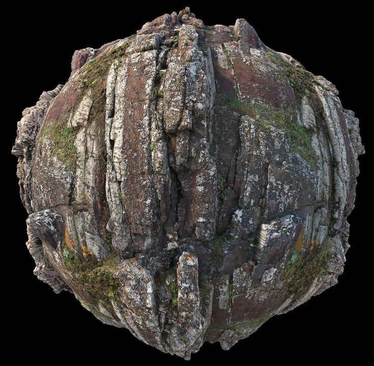 If you are going to scan black, transparent or mirrored objects, we recommend that you treat them with powder or a special anti-reflective spray.
Plain and simple geometric objects can be scanned:
-
By adding auxiliary objects (such as crumpled paper) to the scanned scene
-
Drawing the so-called. markers (e.g. X-shaped) on surrounding surfaces
Create good outdoor lighting. (For details, see Selecting and preparing objects for scanning).
Survey
-
Launch Artec Studio, then point the scanner at the object.
-
Press
F7on the keyboard or the button on the scanner body to start mode Preview .-
Geometry + Texture - Standard mode, suitable for most applications
-
For older computers, mode Geometry is a good alternative to
-
Mode Real-time Fusion creates a model in real time, allowing you to skip post-processing.
nine0018 Click Stop, then check the Real-time Fusion checkbox and click Preview.
-
-
Make sure the subject is clearly visible, then press the button again to start recording. If possible, scan the object from all sides in one pass by smoothly moving the scanner around the object as shown in the figure below.
Note
When scanning, pay more attention to the image of the object on the screen than to the actual object.
-
If you hear a beep and a red error message is displayed, gently aim the scanner at the area you just scanned. There are several reasons for the error "Path tracking aborted":
-
A simple geometric object is being scanned
-
Too small area of object scanned
-
You are moving the scanner too fast
-
-
Click to display the scan in the Workspace panel .
.png)
Rotate and scan (optional)
Note
This part is optional.
Rotate the object and scan any unscanned areas (press ). Capture in the current scan at least one area already captured in other scans, thereby facilitating the assembly operation. nine0003
(See Buttons and LED Indicators, Configuring Scan Settings, Scan Procedure, Positioning Modes, and Real-time Fusion Scan for more details).
Autopilot
For beginners, the easiest way to get the final model is to use Autopilot. Also, this mode saves time for advanced users. If you prefer to do all the steps manually, see Manual processing. nine0003
Autopilot is a special mode that helps users get the final model without learning all the basics of post-processing. It consists of two main parts: semi-automatic (editing and assembly) and automatic [1].
To get the model,
-
Press the Autopilot button on the left panel or press
F9.
-
Familiarize yourself with the steps that you have to go through in this step-by-step mode (listed in the welcome dialog). nine0003
-
On the panel Workspace , check all the scans you plan to work with and click Next.
-
Next, specify the input parameters for the model creation step and click Next. The basic settings include the following:
Note
It is recommended to use tooltips that can be opened by pressing the button next to the option name.
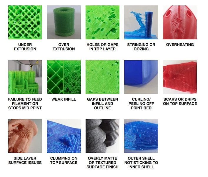
-
Scan quality (geometry) . Click to determine if your scan has a good geometry using hint images.
-
Scan quality (texture) . Click , view the images and decide if your object scan has enough texture.
-
Difficult-to-scan surfaces . Check the box if your object has such surfaces. Use the images that open by clicking on the button for reference.

-
Define Object size using example images.
-
In most cases, you can leave the default values for the rest of the options in this window. For more complex use cases, you can adjust the settings, as noted in the sidebar.
-
-
If necessary, remove any extraneous objects that may interfere with post-processing. Learn how to use the Eraser in the Removing Parts of a Scan (Eraser) section.
nine0018 -
When finished, click Next. If the object was captured in several scans, Autopilot will combine them and show the result. You can accept it or assemble the scans manually (see Manual Rigid Assembly without Specifying Points).
-
Click Next.
-
The autopilot will start processing [1]. As soon as it completes, a message will appear stating that the model is ready. Click the OK button.
| [1] | (1, 2) Automatic steps can include:
|
 noise
noise Manual Processing
Cut Scene
When done, click File and select Save Project . Close panel Scan and pre-registration will start automatically. After that, you will be able to crop the scanned scene.
Purpose: to remove auxiliary surfaces (eg table or floor).
Actions: Open Editor → Eraser → Clipping plane . Follow the instructions.
(See Editing scans for details).
Assembly
Purpose: to assemble several scans together. You can skip this step if you have only one scan on panel Workspace .
Actions:
-
Mark two or more scans with , click the Assemble button and select these scans in tab Hard while holding down the key
Ctrl.
-
Click Auto Build.
-
If the assembly fails due to lack of texture or overlap areas, manually match the feature points on the scans and click the Align button.
(For details, see Assembling scans.)
Global registration
Purpose: to optimize the arrangement of frames among all scans, thus preparing them for further processing. nine0003
Actions: mark the scans using the checkbox, then click Commands → Global Registration → Apply.
(See Global registration for details).
Removing polygonal noise
Purpose: remove individual fragments and polygonal noise.
Actions: Open Commands → Delete polygon. noise → Apply.
(See Editing scans and Removing polygonal noise for details). nine0003
Fusion
Purpose: to create a model (one surface, as opposed to the original scans, consisting of many surfaces).
Actions: select Commands → Smooth Fusion → Apply.
For sharper surfaces, select Clear bonding . For both modes resoltuion can be adjusted: the smaller the value, the more accurate the surface is. nine0003
(For details, see Creating Models (Glue)).
Remove unwanted parts (optional)
Purpose: to remove polygonal noise and poorly scanned areas.
Actions: click Editor → Detail removal brush. Follow the instructions.
(See Editing scans for details).
Simplify the polygon structure
Goal: reduce the file size by reducing the number of polygons and avoiding significant distortion of 3D geometry. nine0003
Actions: click Commands → Simplify polygon. structures → Apply.
(For details, see Simplify the polygon structure).
Texturing
Goal: get a textured model.
Actions:
-
Click Texture .
-
Select the model and the scan(s) from which it was created from the corresponding fields. nine0003
-
Select texturing for Export → Apply.
(See Texturing for details).
Measure, export, publish
-
Export model: open File → Export models... . Select the desired format, specify the destination folder and file name, then click OK.
-
Measure model: open Measure , then select one of the following options:
-
Linear for distance calculation (points connected by lines)
-
Geodesic for distance calculation (points are connected by curves running along the surface of the model)
-
Sections for calculating area and volume
-
-
Publish the model to viewshape.
 com by opening the panel Viewshape nine0059
 -
Restore original settings (
F10→ tab Survey → Restore original. -
To return any parameter from the Commands panel to its previous value, click the small button next to it. The state of the button means that the parameter is currently set to the default value. nine0003
-
Save screenshot using
Ctrl+Shift+S -
Create annotations using Measurements → Annotations , enter the label text edit mode and enter the text, then click Apply.
- All about markers for 3D scanning. - Text: electronic // THOR3D: [website]. — URL: https://thor3dscanner.com/uploads/Markery_dlya_Thor3D.pdf (Accessed: 03/02/2022).
- Kovalenko, R. A. LIDAR as a means of spatial orientation / R. A. Kovalenko, A. A. Sorokin, E. A. Yakovleva // Issues of technical and physical and mathematical sciences in the light of modern research: collection of articles based on materials of the XXXIII International Scientific -practical conference.
 - Novosibirsk: Siberian Academic Book LLC, 2020. - P. 20–25. nine0018
 - Programs for 3D-scanning: review and application in practice. — Text: electronic // Top 3D Shop: [website]. — URL: https://top3dshop.ru/blog/programmy-dlja-3d-skanirovanija-obzor-i-primenenie-old.html (date of access: 03/02/2022).
- Sorokin, A.A. 3D scanner as a CNC machine / A. A. Sorokin, R. A. Kovalenko, E. A. Yakovleva // Russian science in the modern world: collection of articles of the XXXIV International scientific and practical conference, part 1. - M .: OOO "Actuality.RF", 2020. - S. 106–109.
- Sorokin, A. A. Three-dimensional machine vision systems on microcontrollers and microprocessors: monograph / A. A. Sorokin, E. A. Yakovleva, R. A. Kovalenko. - Kazan: Buk, 2021. - 136 p. - ISBN 978-5-00118-733-2.
- Sorokin, A. A. Modeling the problem of texture capture in 3D scanning / A. A. Sorokin, R. A. Kovalenko // Issues of technical and physical and mathematical sciences in the light of modern research: collection of articles based on materials of the XXXIV international scientific and practical conference .
 - Novosibirsk: Siberian Academic Book LLC, 2020. - P. 33–37. nine0018
(For details, see Export models and scans, Publishing to the site and Measurement tools).
Tips and tricks
Optimal marker selection for 3D scanning with color texture capture
Author : Shishigin Denis Sergeevich nine0003
Academic Supervisor : Sorokin Alexey Andreevich
Category : Engineering sciences
Posted by in young scientist #23 (418) June 2022 nine0003
Publication date : 06/08/2022 2022-06-08
Article viewed: 39 times
Download electronic version
Download Part 2 (pdf)
References:
Shishigin, D. S. Choosing the optimal marker for 3D scanning with the ability to capture a color texture / D.S. Shishigin. - Text: direct // Young scientist. - 2022. - No. 23 (418). — pp. 123-127. — URL: https://moluch.ru/archive/418/92760/ (date of access: 12/23/2022).
The article deals with the use of markers in 3D scanning and the choice of their optimal options for use in working with scanners that capture texture.
Keywords: 3D scanner, marker, texture capture .
Introduction
A marker is a small sticker or magnet that has a black circle with a white dot on it. The 3D scanner uses these high contrast images to determine its position in space (Figure 1). To improve the accuracy and stability of 3D scanning, markers are applied directly to the object itself or next to it [1]. nine0003
This approach to using markers is classic. At the same time, markers often need to be applied in a hurry, but the resolution and technical features of the scanner allow using other objects as a marker. This article is devoted to this issue.
Fig 1. Markers for 3D scanners
What are markers usually used for?
Without markers, the scanner will lose orientation during scanning, and it will be impossible to correlate adjacent frames. Based on the markers, the software performs comparison by adjacent markers, using them not only for positioning, but also for scaling different frames, which allows you to position portable scanners arbitrarily without adjusting the distance to the object. For this, complex algorithms are used, which are different for different types of scanners, which help to understand and make a decision that, for example, a person’s nose from one frame should coincide with the same nose from another and not with another part of the body or object. nine0003
During the entire scan, the scanner must see at least 3 markers in each frame. If there are less than three markers, the scan will automatically stop. With a minimum of 3 markers per frame, the optimal number of markers per frame is 5. This is necessary to exclude such situations when the marker, although it is in the field of view of the scanner, is not recognized by it (for example, due to reflection). Therefore, when pasting an object with markers (Fig. 2), they try to place them in such a way that there are 5 markers on any area of 70x100 cm [1]. nine0633
Rice. 2. Object with markers
When sticking markers on flat surfaces of an object, avoid hitting the corners. The 3D scanner will not be able to see the marker at an awkward angle. In order for corners to be scanned easily (for example, continuous scanning from the trunk of a car to its door), the number of markers closer to the corner zone is increased.
With or without markers, an optical 3D scanner more accurately measures the area that falls in the center of its frame rather than at the edge. If, when digitizing an object, each of its zones is at least once in the center of the scanner's field of view, this guarantees the best result. nine0003
This approach is used for scanners that perform partial capture of an object and are most often photogrammetric or optical. The use of scanners based on LiDAR technology [2], combined with a capture and texture generation tool, simplifies the work, requires hitting only three markers, which are most often used to position an object or obtain its spatial position [3].
Alternative markers
Marker requirements:
- The marker must be in contrast with the object
- The marker must have a fixed shape
- Marker size must be constant
— If the marker is used for scaling and positioning, then its placement must be predefined.
The choice of a marker with the possibility of its detection on the scan results in the described type of scanners is due to the following features [4]:
- The point cloud is merged into a polygonal mesh during scanning or immediately after it nine0003
- Image fragments are converted into texture fragments and mapped to vertices/polygons
- The marker is detected on the surface texture, its size and shape are compared with the standard.
Markers that fit this description should have a simple regular geometric shape. And the geometric centers of markers should be taken as a basis for positioning and scaling objects.
The optimal shape of the marker (Fig. 3):
- Round marker nine0003
- triangular marke
- Square marker
The optimal type of marker (Fig. 3.):
- Bright yellow color
- Bright green color
- Bright red color
- Bright orange color
- Bright blue color
- White color
- Black color
- Two-color marker with a checkerboard coloring of contrasting colors (for a square marker divided into 4 equal parts - Fig. 4). nine0003
Rice. 3. Marker Options
Rice. 4. Two-color markers
The choice of the shape and appearance of the marker is determined by the following factors:
— The geometric figure must be distinguishable and easily recognizable regardless of the shape of the surface to which it is attached
- Finding the center of the figure should fit into finding the middle between the extreme points in all three coordinates
— Markers should be contrasting to the object under study nine0003
Additional features of using markers
If it is necessary to capture the original texture of the entire surface, markers will be optimal, the color component of which can be easily excluded from image analysis [5]. The number of markers used in this case must be reduced to 5 or more, and during scanning, one by one, remove them from the object, leaving at least three active and visible to the scanner, which will allow you to compare the extended scan results with the results of the first pass and identify replaced texture fragments [6] . nine0003
Conclusion
In the course of writing this article, the current 3D scanning techniques were analyzed, the tools used in 3D scanning, in particular, markers for positioning, were identified. The approach to the use of these markers and the conditionality of their geometric shape, appearance and features of use are analyzed.
For the selected scanning method, adequate alternatives to the markers used were selected, taking into account the design and technical features of the scanning device. Conclusions were drawn on the features of the operation of the selected markers, taking into account their geometric and color features. nine0003
Additionally, a technique was proposed for scanning objects using these markers, in which it is possible to remove them from the surface texture of the final object. The results of this study will be further applied when performing the final qualification work on modeling the comparison of the results of scanning damaged surfaces with a reference object. In the future, this topic can be developed into a full-fledged software or hardware-software complex.
Literature:
Basic terms (automatically generated) : marker, scan time, marker usage, frame, square marker, positioning, scanner, surface texture.
Keywords
marker, 3D scanner, texture capture3D scanner, marker, texture capture
Similar articles
Modern systems 3D
scanning | Journal article... The 3D Scanner works like a regular video camera, capturing 3D surfaces at up to 15 surfaces per second. Therefore, the process of scanning objects becomes extremely simple - you need to go around and shoot the object from various angles. nine0003
Requirements for the development of specialized labels for...
This article is devoted to the development and proofreading of markers for AR applications. This paper displays the process
Quality of label preparation for projects with using augmented reality , in particular for software products with AR ...
Shishigin Denis Sergeevich — Information about the author nine0291
Selection of the optimal marker for 3D scanning with the ability to capture the color texture . №23 (418) June 2022 Authors: Shishigin Denis Sergeevich, Sorokin Alexey Andreevich (supervisor). Rubric: Technical sciences. Pages
Markers play space | Journal article...
Savitskaya, N. M. Game space markers / N. M. Savitskaya, L. O. Safonova, O. I. Lavrent'eva. nine0003
Analyze already existing game space markers . Choose a material that meets hygienic, aesthetic requirements.
3D Scanning Method for Flat Templates
This Laser Scanner will replace the plotter and CMM in your workflow. This will significantly simplify the process of controlling templates and significantly increase the accuracy of parts. 3D- scan is a systematic process of determining the coordinates of points belonging to surfaces ...
Applications of RFID technologies in the activities of various...
Access control. · Reduced time spent searching for what you need. Currently possible areas of application of RFID technology are: Logistics. RFID technology offers an original and modern solution for accounting and control of goods in a warehouse.
Economic efficiency
application three-dimensional... This article covers the topic of application of 3D- scanning as a way to reduce the cost of surveying and measuring work in construction and architecture.
3D scanning technology is gaining more and more attention due to its rapid development.
Using MFL technology to detect corrosive...
When scanning the surfaces of with a multi-channel transducer can be determined
5. Trajectory scan multi-channel primary measurement
Elastic cuffs provide positioning of the system, protection of elements from chemical and...
Computed tomography: technical aspects of quality...
Scanning of is performed according to the standard method, which takes several minutes; then the patient is released and the next one is called. nine0003
CT technology is improving, reducing scan time and improving image quality.
Similar articles
Modern systems 3D
scanning | Journal article...The 3D Scanner works like a regular video camera, capturing 3D surfaces at up to 15 surfaces per second. So process scan objects becomes extremely simple - you need to walk around and shoot the object from various angles.
Requirements for the development of specialized labels for...
This article is devoted to the development and proofreading of markers for AR applications. This paper shows the process
The quality of label preparation for projects using augmented reality , in particular for software products with AR...
Shishigin Denis Sergeevich — Information about the author
Selection of the optimal marker for 3D scanning of the with the ability to capture the color texture . №23 (418) June 2022 Authors: Shishigin Denis Sergeevich, Sorokin Alexey Andreevich (supervisor). Rubric: Technical sciences. Pages
Markers play space | Journal article... nine0291
Savitskaya, N. M. Game space markers / N. M. Savitskaya, L. O. Safonova, O. I. Lavrentieva.
Analyze already existing game space markers . Choose a material that meets hygienic, aesthetic requirements.
3D Scanning Method for Flat Templates
This Laser Scanner will replace the plotter and CMM in your workflow. This will significantly simplify the process of controlling templates and significantly increase the accuracy of parts. 3D- scanning is a systematic process of determining the coordinates of points belonging to surfaces ...
Applications of RFID technologies in the activities of various.
 ..
.. Access control. · Reduced time spent searching for what you need. Currently possible areas of application of RFID technology are: Logistics. RFID technology offers an original and modern solution for accounting and control of goods in a warehouse. nine0003 This article covers the topic of application of 3D- scanning as a way to reduce the cost of surveying and measuring work in construction and architecture. 3D scanning technology is gaining more and more attention due to its rapid development. When scanning the surfaces of with the multi-channel transducer can be determined fig. Cost Efficiency Of
Application Of Three Dimensional...
Using MFL technology to detect corrosive... nine0291 
Learn more