Intel 3d scanner
Review of The Intel RealSense D415 Using Intel RealSense SDK
3D scanning and Scan to BIM is one of the fastest growing segments of the construction industry, be it in the industrial sector or the commercial sector.
There are many competing technologies and techniques that seem to pop-up every day, photogrammetry, time of flight (depth-sensing) based scanning, and of course laser scanning are the three dominant technologies currently in use and development.
Being a small business in a developing nation, laser scanners were out of our price range, so we’ve opted for the first two techniques; photogrammetry and depth-sensing based scanners (Later we’ve tried testing Intel D515). We’ve dappled with photogrammetry but the process require huge computing power as well as very laborious photo-shoots, so we’ve decided to test the Intel RealSense platform.
Intel RealSense for scanning
This review will focus only on using the Intel RealSense D415 as a scanner and not for any other application ( robotics, object tracking, etc. ).
At the time of deciding which camera to buy (late 2018), two main cameras were available; the Intel D415 and the Intel D435, other cameras like SR300 were nearly discontinued.
After doing our due diligence (prolonged research) we’ve found that the results from the D415 were better than the D435, it has less distortion and an overall better scan quality without many voids.
RealSense SDK
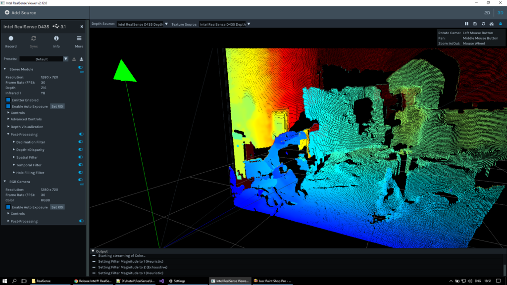
The first challenge we’ve faced was the SDK from Intel, the new SDK (V2) doesn’t have any scanning application unlike the old SDK. You can scan and get a .bag file.
First, the size of the file is huge, second, you can’t convert it to a point cloud, we’ve tried every trick using ROS, MATLAB, etc. and non was successful.
We had to rely on third-party software like Dot3D and RecFusion, there will be a separate post covering each of the software in details, for now, you’ve to understand that you can’t use the SDK to get an STL for 3D printing or a point cloud of the scan that you can use later in your BIM Software.
It’s also worth noting that you can capture a still STL using the SDK, it is like a photo but with some depth data, if that is what you seek.
Small Scans with Intel RealSense D415
We’ve tried using both software (Dot3D and Recfusion) to scan small mechanical spare parts and instrumentation, the results were very bad (nearly unusable) in any professional capacity, the scans were so bad that I can’t include in this post, it was nothing but a blob.
Large Scans with Intel RealSense D415
We had better results with larger scans, again none of them could be professionally submitted to a client, results from Dot3D (as seen below) were better but again not for professional use. The more complex the area we were trying to scan the more voids and the more cumbersome the scan becomes. we’ve even returned to photogrammetry as for many scans the results were better and the process was easier.
Dot3D Scan with D415If you want to use the Intel RealSense D415 in a professional capacity for complex site scans, it is better to seek an alternative, but if you want to scan a room or a simple space then it is a good option. In the coming posts, I’m going to compare between RecFusion and Dot3D.
Like this:
Like Loading...
[How-to] Easy way to scan the surrounding environment in 3D (RealSense)
This article summarizes an easy way to 415D scan your surroundings using the Intel RealSense Depth Cameras (D435, D435, D515i) and LiDAR Camera L3.
Some software is required for 3D scanning (converting an object into 3D digital data), but it can be achieved with relatively simple steps.It is a procedure to scan the surrounding environment in XNUMXD and create a room with Mozilla Hubs, so we hope you find it helpful.
* This article refers to the following WEB pages
How-To: A Simple Way to 3D Scan an Environment
https://www.intelrealsense.com/3d-scanning-an-environment
table of contents
- first
- About Hubs
- Step 1: Perform a scan
- Precautions when scanning
- * Reference video
- Step 2: Convert to OBJ file
- Acquisition of color information
- Step 3: Convert to GLB file
- Step 4: Import to Hubs
- Finally
first
You need to choose different file formats to suit your purpose and software, such as 3D scanning and 3D modeling. There are several data formats and file formats in this article as well.First of all, I will give you a brief explanation.
・ PLY file format
3D image file format for storing XNUMXD point cloud data
・ OBJ file format
A simple data format that represents a three-dimensional spatial object (geometry) in one of the 3D model formats.
・ GLB file format
Binary file format of 3D models stored in GL Transmission Format (GLTF) for transmitting 3D models
After 3D scanning the surrounding environment, we aim to finally publish it on the VR-friendly platform "Mozilla Hubs" while saving the data according to the software used.
About Hubs
Hubs is Mozilla's Mixed Reality (Mojira), known for its web browser.Mixed reality) A free VR friendly platform created by the team.Through this open source social VR space, various simulated experiences are possible.Not only can you bring third parties into your space, but you can also create new rooms and import models to share them.
Step 1: Perform a scan
There are many applications for 3D scanning using Intel's RealSense depth camera, but this time we will use the file export function of "Dot3D Pro", which has a reputation for ease of use.
This demonstration uses Microsoft Surface Pro 4 (6th generation). It works on any device (desktop, laptop, etc.) as long as it is compatible with "Dot3D Pro", but you may need a USB cable of sufficient length.Also, depending on the distance to the object to be scanned, it may be necessary to consider the hardware installation location and wiring.In that respect, tablet selection has less restrictions on the installation location and hardware side, and the process of scanning the surrounding environment becomes easier.
1-1. Start scanning
Be sure to use USB 3 cables and ports when using Dot3.0D Pro.
Connect the camera to your tablet and open the software.Select the connected camera in the software settings window.
Then choose to create a new scan and select the Scan icon to start the scan.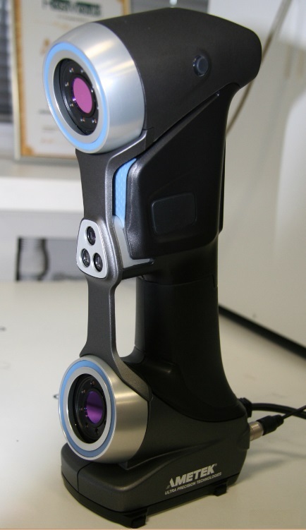
As you move the camera, the pixels in the camera feed turn white, yellow, or green.Green means that the area has been completely scanned.For a complete scan, take the time to move around the area with small movements to fill the gap.
You can also use the host device's camera while scanning to capture the area you are scanning as a high-resolution RGB still image.You can refer to and use this still image when working with your model in a 3D package like "Blender" or "Maya" for later work.
When you are satisfied with the scan data, tap the scan button again to finish the work.Optimize your model here.It may take several minutes depending on the size of the scanned file.After optimization, scan the PLY file (3D /Point cloud file format).
Precautions when scanning
1. Avoid extremely bright places
Avoid extremely bright areas such as direct sunlight when scanning outdoors, as it can cause problems in accurately scanning the space and the resulting model may appear inconsistent. Please give me. When using the L515, scan only in indoor spaces for better model results.
2. Avoid dark and glossy materials
Objects made of materials that are very dark and reflect light, such as glossy black tables,Because there is a possibility that parallax cannot be obtained and the distance cannot be calculated.Avoid as much as possible.
See this article for a comparison of scan data in different environments.
* Reference video
The entire process of capturing and processing scan data from the newly supported Intel RealSense Depth Camera D455 and LiDAR Camera L515.
Master Class in Dot 3D ™ 4.0: Intel® RealSense ™ Handheld 3D Scanning
Step 2: Convert to OBJ file
PLY file (3D /Point cloud file format) Stores the 3D data (3D model) acquired from the 3D scanner, and can be used as it is as a 3D model.For example, 3D viewer “SketchfabYou can upload a 3D model to “and easily share (publish or share) it as 3D, VR, AR content.
However, PLY files are very large, so it is recommended to convert them to mesh format if you want to increase file processing and flexibility. The method of converting point cloud data (PLY file) to OBJ file using "Meshlab" is as follows.
2-1. Import PLY fileOpen “Meshlab” and go to File> Import Mesh on the toolbar.Import the PLY file you exported in step 1.
"Meshlab" where the imported mesh is displayed2-2. Clean the mesh data
As it is imported, it is not yet complete data.Perform some further operations to clean the point cloud data (point cloud data) and convert it to mesh data.Depending on the appearance of the file, you may mess with the settings or remove unnecessary vertices.In that case, the following procedure is recommended.
2-2-1.
Use the Select Vertices tool at the top of the toolbar to select a group of vertices.Then use the Delete the current set of selected vertices tool to delete it.
2-2-2.
Filters> Sampling> [Poisson-Disk Sampling (Go to Poisson Disc Sampling)]
Make sure "Base Mesh Subsampling" is selected on the settings screen and change the number of samples to tens of thousands (35,000 was selected here).The higher the number here, the more sophisticated the final mesh will be.Note that the number of polygons (the number of triangles) affects the operation of the mesh in other programs and applications, so do not set it too high.
There is no image here, but the layer menu on the right shows the original point cloud and Poisson disc sampling.Delete the original mesh as it is no longer needed.
2-2-3.
Filters> Point set> Compute normal for point set (Calculate surface normals )]
Change the mesh neighbor number to 16 and execute.It is trying to automatically determine the normal vector of each point (which direction each face points to) in order to generate faces with the Marching Cubes method.
2-2-4.
Select Filters> Remeshing, Simplification and Reconstruction> Surface Reconstruction: Ball Pivoting
A single click on the up arrow in the World Unit Box next to "Pivoting Ball Radius" will auto-populate the appropriate value.When applied, a mesh will be created instead of the point cloud.Repeat the steps of going back and changing the parameters little by little until you are satisfied with the mesh you created.
Acquisition of color information
Here, we will also show you how to get the existing color information when exporting from "Meshlab".
Run Filters> Texture> Parametrization: Trivial Per triangle.If an error occurs, change the value of the border between the triangles to 1.
Execute [Filters]> [Texture]> [Transfer Vertex color to texture].At this time you will be asked to save the project.Save the texture file with the suggested name "project name".As for the save name, "_tex.png" is added to "Project name".
Export as an OBJ file to the same folder.Make sure all available checkboxes are selected.The texture file you just created is displayed in the box on the right.This file type can also be used with 3D packages such as "Unity" and "Unreal" and game engines.
The next step is to move from “Meshlab” to the open source 3D modeling tool “Blender”.
Step 3: Convert to GLB file
Open “Blender” and import the OBJ file.If you're having trouble importing a file, click View in the upper left corner of the viewport and select the Sidebar check box.
To the right of the viewport, there is a tab labeled "View".Clip start and end parameters0.01mと10000mChange to each.
Zoom in and out until you see the model.It may be upside down, so rotate it to shrink it a little.
Models in Blender: The highlighted "Rotate" tool is on the left and the "View Panel" is on the right.
Click the model displayed next.Select the "rotate" icon on the left side of the screen and use the directional ring to adjust until you can see that the floor is in the correct orientation.
At the same time, shrink the model at this stage.You can fine-tune the final size in the next step, but we recommend a size of around 10%.
You may also notice that the model has no texture.At the top right of the viewport window are several viewport shading icons. Select "Material preview" to see the color of the model.
You can also use the “Blender” editing tools to fill in the holes and remove the outer faces to make the mesh look better (there are many tutorials to help you clean the mesh, so I won't cover it here). ..
When you are satisfied with the created mesh, export it as "GLTF 2.0".The actual file extension required is the binary version of gltf, ".glb".
Step 4: Import to Hubs
Open Firefox andhubs.mozilla.com Go to and sign in to your account. Click Create a room, Choose Scene, and select Create a scene with Spoke.
Select Empty Project to create a new project.
The avatar and crater terrain that represent the spawn point are displayed. Click "My assets" in the lower left panel.Upload the .glb file you exported in step 3 here and drag and drop it into the hierarchy panel just above the crater terrain.
Use the spawn point icon and crater terrain as a guide to scale your scene.This time I scaled the mesh from its original size to 0.002.You can keep or hide the crater terrain and add objects such as lights.
Spoke window showing the final scene of the hierarchy and viewport, scaled to the spawn point model
When you're happy with the result, select Publish to hubs.Since the mesh is very precise data, it may not work well on mobile, such as when there are too many polygons (number of triangles).Ideally, the mesh should be reduced to less than 50,000 polygons during the “blender” stage to improve performance.Make sure all other performance parameters are okay and publish the scene by selecting view your scene> Create a room with this scene. To do.
In the room, you can share the link with others to show your 3D scan.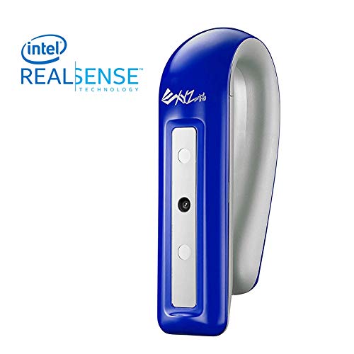 This flow should also work for point cloud objects scanned using “Dot3D Pro” or other Intel RealSense-enabled software.
This will create a social VR space where anyone can chat with the creator (you) via a browser and enjoy a virtual space using a VR headset.
The image below is the final scene I made this time.Of course, work is needed to further optimize and improve the mesh created from the original high quality scan, but we have demonstrated that this workflow can be used to create a 3D environment.
Social VR 3D scanning environment in Mozilla Hubs portal
Finally
We handle Intel's RealSense D series, LiDAR camera L515, etc. mentioned in this article.Service for R & D "Rental servicetegakariFeel free to try the actual machine.Please feel free to contact us regarding usage.
Сappasity 3D Scan - 3D scanning using Intel RealSense. Development experience / Habr
In 2014, we decided to launch a software startup where we could use our five years of experience in 3D technologies gained in game development.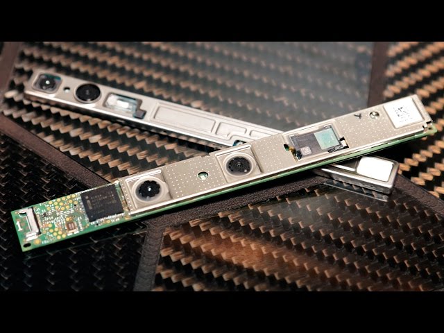 The topic of 3D reconstruction has been of interest to us for a long time, and throughout 2013 we conducted numerous experiments with solutions from other companies - this is how the desire to create our own gradually accumulated. As you probably already understood, our dream was successfully translated into reality; the chronicle of this incarnation is under the cut. There is also a history of our relationship with Intel RealSense. nine0003
We had previously done stereo reconstruction for our own needs, as we were looking for the best way to produce 3D models, and the use of 3D capture solutions seemed quite logical. 3D scanning using a handheld scanner seemed like the most affordable option for us. In advertising, everything looked simple, but it turned out that the process takes a lot of time: tracking is often lost and you have to start from the very beginning. But most of all upset the blurry texture. That is, such content for games was not suitable for us. nine0005
We looked at photogrammetry and realized that we didn't have an extra $100,000 dollars.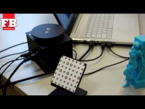 In addition, it required special skills in camera setup and then a long post-processing of high-poly data. It turned out that we definitely did not save anything, but, on the contrary, everything became much more expensive, given our content production volumes. It was at this moment that the idea arose to try to do something of my own.
Initially, we thought out the requirements for a system that would be convenient for content production:
- Stationary system - calibrated once and can be removed.
- Snapshot - clicked and done.
- Ability to connect SLR cameras for photorealistic texture quality.
- Independence of the system from the type of sensors - technologies do not stand still, and new sensors appear.
- Full implementation of client-server technology. Each client is a computer with a sensor.
- No restrictions on the number of devices - we may need to instantly capture objects of different sizes and, therefore, any restrictions will cause problems.
 nine0012
 - Ability to print the model for 3D printing.
- Availability of a browser plug-in and an SDK for integration into mobile applications.
This is the dream system. We did not find analogues, so we wrote everything ourselves. Almost a year has passed, and in the fall of 2014, we finally got the opportunity to tell potential investors about our achievements. And already at the beginning of 2015, we demonstrated a system assembled using Intel RealSense sensors at CES 2015.
But what happened before that?
Writing a network code with its own data transfer protocol paid off immediately. We have been working with PrimeSense sensors, however, if there are more than two sensors on one PC, they functioned extremely unstable. At that moment, we did not think that Intel, Google and other market leaders were already working on new sensors, but out of habit we designed an expandable architecture. Accordingly, our system easily supported any of this equipment.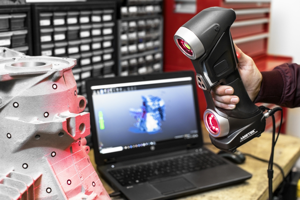 nine0005
Most of the time was spent writing the calibration. The well-known calibration toolkits were not ideal, since no one deeply analyzed the anatomy of PrimeSense sensors and far from all the parameters we needed were calibrated. We ditched the PrimeSense factory calibration and wrote our own based on IR data. Along the way, a lot of research was carried out on the functioning of sensors and algorithms for constructing and texturing a mesh. Much has been rewritten and redone. As a result, we forced all the sensors in our system to shoot the same way. And having forced, they immediately filed for a patent and at the moment we have U.S. Patent pending. nine0005
After PrimeSense was bought by Apple, it became clear that it was worth switching attention to other manufacturers. Thanks to the developments already available at that time, the software with Intel RealSense sensors started working in just two weeks after receiving the sensors from Intel. We now use Intel RealSense, and for long distance filming we use Microsoft Kinect 2.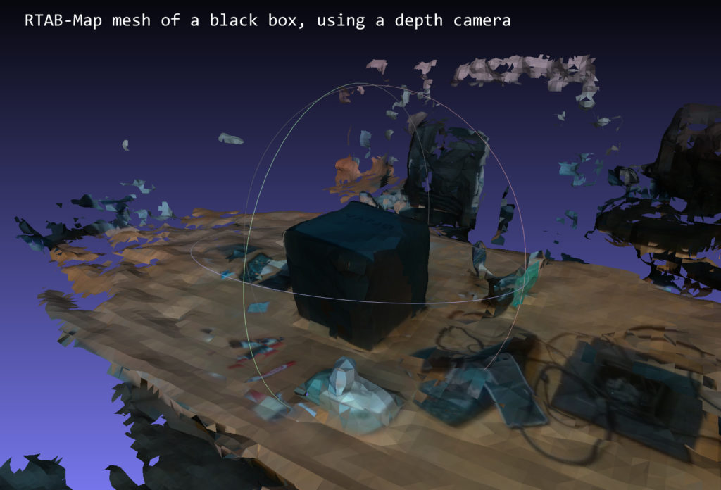 Recently watched Intel's CES keynote on the topic of sensors for robots. Perhaps they will replace the Kinect 2 for us if they become available to developers. nine0005
When switching to RealSense, a calibration problem reappeared. In order to color the points of the cloud in the appropriate colors or to texture the mesh obtained from the cloud, it is necessary to know the positions of the RGB and Depth of the camera relative to each other. RealSense was originally going to use the same proprietary manual scheme as PrimeSense, but we ran into a sensor limitation - data came in after filtering, and working with RAW requires a different approach. Fortunately, the Intel RealSense SDK has functionality to convert coordinates from one space to another, such as from Depth Space to Color Space, from Color to Depth Space, from Camera to Color, and so on. Therefore, in order not to waste time developing alternative calibration methods, it was decided to use this functionality, which, surprisingly, works very well. If we compare the colored point clouds with Primesense and with RealSense, then the clouds with RealSense are colored better. nine0005
What did we get? Sensors and cameras stand in a circle around the object being filmed. We calibrate them and find the positions of sensors, cameras and their tilt angles relative to each other. Optionally, we use Canon Rebel cameras for texturing as they are optimal in terms of price/quality. However, there are no restrictions here, since we ourselves calibrate all optical parameters, including distortion.
Textures are projected and blended directly onto the 3D model. Therefore, the result is very clear. nine0005
The 3D model is built from point clouds that we form from N sensors. The data capture speed is from 5 to 10 seconds (depending on the type and number of sensors). And we get the complete model of the object!
View 3D model
Preview 3D model:
This year we plan to release 4 products at once: Сappasity Human 3D Scan for scanning people, Сappasity Room 3D Scan for rooms, Сappasity Furniture 3D Scan for furniture and Cappasity Portable 3D Scan to scan using a single sensor.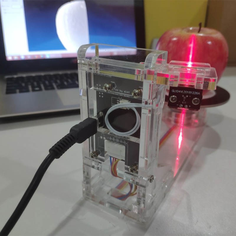 nine0005
Cappasity Portable 3D Scan will be released in just a couple of months for laptops with Intel RealSense. We will present it at the GDC 2015 conference held on March 4th in San Francisco. You can create high-quality 3D models using a turntable or manually rotating the model. Moreover, if you also have a camera, then we will give you the opportunity to create high-resolution textures.
Why did we choose Intel RealSense? We decided to focus on Intel technology for several reasons:
- About 15 notebook models support RealSense;
- plans to release tablets with RealSense;
- opens the way to B2C sales - a new direction for monetization of our products;
- has a quality SDK;
- sensors are characterized by high speed.
Good technical, marketing and business support from the company itself also plays an important role. We have been working closely together since 2007, and there has never been a situation where we could not get an answer to our questions from colleagues from Intel. nine0005
If we consider RealSense technology in terms of 3D scanning at a distance of up to one meter, we can safely call Intel a leader in this field.
Undoubtedly, modern technologies open up great opportunities for working with the depth of the world around us!
We regularly post updates on our progress on our Facebook and Twitter pages.
3D Scanning with Intel RealSense / Sudo Null IT News
The recently released SDK for the Intel RealSense F200 camera includes 3D scanning functionality. This is an amazing feature that will allow developers and graphic artists to scan real objects and apply them to their projects. One example of using this technology is scanning real objects for use in the Unity game engine. In this article, I will walk you through the details of this process. nine0003
What will you need?
- Intel RealSense Camera with 4th generation Intel Core processor or higher with SDK installed (SDK is free)
- Object scanned with Intel RealSense technology and converted to a PLY file (using the free MeshLab software)
- Blender (freeware)
Scanning with Intel RealSense SDK
Install the Intel RealSense SDK. Open the Windows Express Button Bar and search for RealSense. You will see RealSense SDK Sample Browser listed. Right-click it and select "Run as administrator". nine0005
In the Sample Browser you will see the Common Samples tab. These are examples that work with both the F200 and R200 cameras. Find an example called 3D Scan (C++).
3D Scanning Things to Know
- This example is designed to trace a rigid 3D object in space as the object rotates in front of the camera, allowing the object to be scanned from various angles.
- If one part of the object rotates while the other does not, it will make tracing difficult and result in a poor quality scan. For example, if you are scanning a head, do not rotate it relative to the neck, otherwise this will degrade the scan quality. Instead, it is better to rotate the entire torso so that the camera perceives it as a single object. nine0012
- You can lean forward and backward, turn your torso to the right and left, and do a full circle.
 Over time, you can learn to scan objects by rotating them 360 degrees.
 - Scan objects in even light. Avoid shadows as shadows or light reflections will also be brought into the 3D texture.
Scanning steps.
Select Run in the Sample Browser.
- Place an object in front of the camera and you will see it displayed in the scanner. Wait for the second window to appear. nine0012
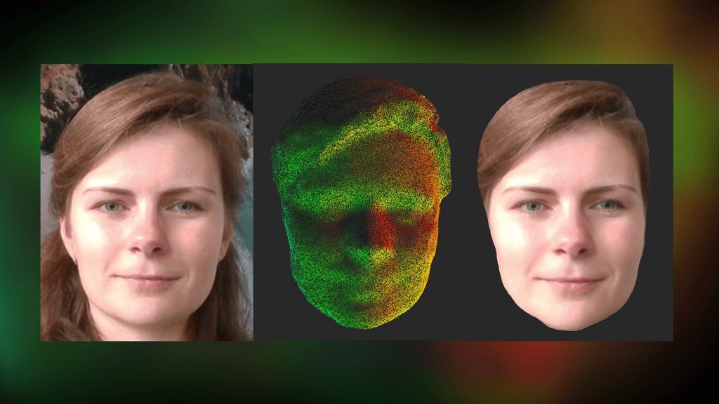
- As soon as the second window appears, start rotating the object in one direction, then in the other, and then 360 degrees. After that, tilt the object back, then forward, then hold it in its original position. If you are scanning a face, you should look straight ahead over the camera for the last few seconds so that your eyes are fixed in the same position.
- When the scan is completed, a web browser window will open where you can move and rotate the resulting image. The image is saved in your Documents folder as 3Dscan.
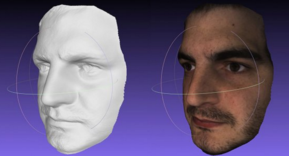 obj. nine0012
 - You can use this example an unlimited number of times to create high-quality scans that you can modify and use in your applications or games.
PLY file conversion
When scanning, files are saved in the OBJ format by default. You can convert the file to PLY format with the free tool MeshLab.
Download and install MeshLab (free).
From the File menu, select Import. Select the 3Dscan.obj file located in the root of the Documents folder. nine0005
The imported object may be rotated on its side. You can left click on the bottom of an object and drag to rotate the object and view it. You will see a grid with a colored texture. The color information is stored in the Vertex Colors format, i.e. each vertex is colored with pixels in the RGB colors received by the camera during scanning.
From the File menu, choose Export Mesh As.
In the dialog box, select Stanford Polygon File Format (*. ply). nine0005
Specify the path when saving, which you can then find.
Now we can get to work in Blender, where you can clean up the mesh and convert the Vertex Colors to UV map format.
Blender Vertex Colors and UV Map
The point is to import the 3D model file and make a copy of it. Then we need to clean up the copy and use the vertex colors as the UV map in the new version of the model.
Create a new project in Blender, select Import PLY and select the PLY file exported from MeshLab. nine0005
After import, you will see that the textures are missing.
If you switch to Texture view, you will see that the RGB colors from the scanned model are now mapped to Texture mode.
Switch to the Materials view to display the colors correctly. In the panel on the right, select the Materials icon. Create a new material. In the panel editor, set the Shading to Shadeless, and in the Options section, check the Vertex Color Paint checkbox. This will assign the vertex colors to the material of the object. nine0005
As you can see, it is impossible to work with such a model. It is full of holes, and the number of polygons is much higher than necessary. We need to create a version of this model that can be cleaned up and represent the texture with vertex colors as a UV map. This is the version we are importing into Unity.
Duplicate the model
Go to the Object menu. Select Duplicate Mesh and press Enter. Do not move the mouse pointer.
Go to the Object menu, select Move To Layer and select the square on the right.
Go to Resource Explorer and rename the models. For example, let's call the first model "original model" and the second one "second model". This will help keep order.
Select the second model, select the level to view and switch the mode to Solid rendering.
Then click on the Tool Wrench icon to add a modifier. We will change the number of polygons in the second model and thus make it cleaner. nine0003 Select Remesh from the Tools menu. In the Remesh toolbox, enter a value between 7 and 8 for the Oct Tree parameter. Select the Smooth mode, check the Smooth Shading checkbox. This will remove the mapping to materials.
Click Apply. We now have a cleaner model that we can apply the vertex and UVMap to.
Switch to edit mode for this second model. From the Select menu, choose Select All.
Create a new window and set its UV Map mode to display the UVMap. nine0005
In the 3D window, go to the Mesh menu and select UV.
In the UV Map window, select NEW to create the texture. Uncheck Alpha. Give the texture the name of the model to be exported.
Switch to Object mode. You will see a black model and a black UV map. This is fine.
Now turn both layers on with the Shift key.
In the resource browser, select the original model.
Click the camera icon. nine0003 In the Bake area, check the Select to Active box. Make sure the Bake to Vertex checkbox is unchecked.
In the Scene section, set Color Management to None.
In the Asset menu, first select the original model. Then, while holding down the SHIFT key, select the second model. (In that order.) Both layers should be visible with the eye and camera icons enabled.
Click the camera icon. In the Bake section, click Bake. nine0005
The texture should now be mapped to the map. To verify this, turn off the first layer so that only the second model layer remains. Switch to the Texture view and you will see the model with a UV map applied as a texture.
Note some image instability in missing areas of the model.
You can switch to Texture Paint mode and fix these issues. You can also now switch to Sculpt mode and fill in missing places, clean up the model, or add new elements to it. Now the model is ready, it can be exported. And the last thing to remember. nine0003
- Make sure the UVMap has the same name and is in the same folder as the model.
- Go to the UVMap window, select Save As from the Image menu and select the folder where you want to save the model.
- Then go to the File menu and export the file in .FBX format with the same name as for the UV map.
You are now ready to import this 3D model into Unity.
Importing files into Unity
After completing the steps of the previous part, you should have a .FBX model with a UV texture map.
Open Unity (Unity 5 is available as a free download).
Create a new project and scene.
From the Assets menu, select Import new asset. Select the .FBX model you exported from Blender.
When importing an object, it is quite possible that its texture is not imported. nine0003 In this case, you will see a light gray version of the grid. This is fine. Now we will add a texture map.
Select the Materials folder, right-click and select Import Asset. Select the PNG file you saved in Blender and import it.
You will now see the texture map next to the gray material. Right-click on the gray ball-shaped material that has the same name as your mesh and delete the material. nine0005
Go back to the Assets folder and right click on the mesh you imported. Select Reimport.
After re-import, the material is created correctly and the mesh is displayed with the desired texture.
If the model is shown in pink in the viewport, simply select another object, such as a camera, and then select your mesh again. Now it should display correctly.
The object is now ready for use. Drag the object to the stage. You can zoom in and adjust the camera to get the view you want.
By moving the camera, you should see your object render correctly in Unity.
Finally, if you want to edit the texture, for example make it more or less shiny, go into the Materials folder and select the ball version of your texture.