Hurdy gurdy 3d print
▷ hurdy gurdy 3d models 【 STLFinder 】
Hurdy Gurdy
sketchfab
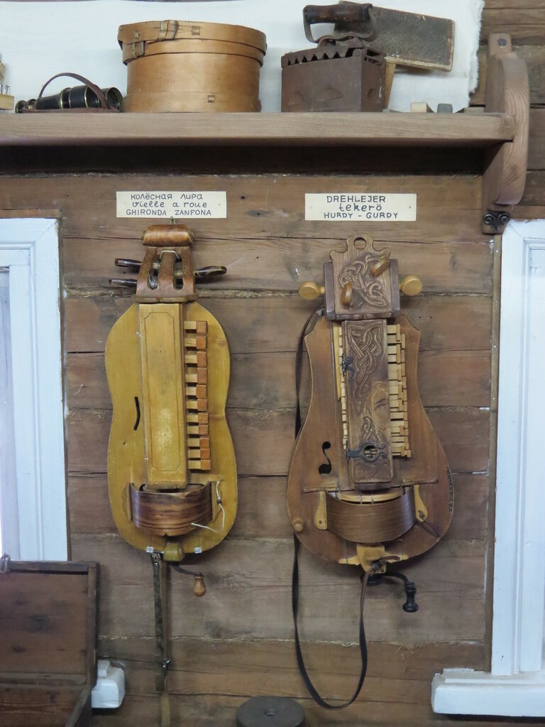
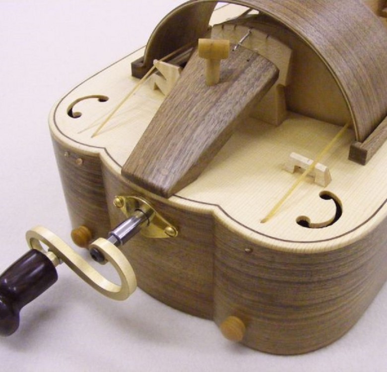
If you’re unfamiliar with what this is, it’s basically a stringed instrument, similar to a violin. However, instead of a bow, the musician turns a crank that bows the strings, and then uses the keys on the side to play the melody. The song you hear...
hurdy gurdy
grabcad
The hurdy gurdy or hurdy-gurdy is a stringed musical instrument that produces sound by a crank-turned rosined wheel rubbing against the strings. The wheel functions much like a violin bow, and single notes played on the instrument sound similar to a...
Hurdy gurdy 3D model
cgtrader
Blender 2. 79
Nerdy / Hurdy Gurdy Knob
thingiverse
Traditional sized knob for Nerdy Gurdy, to use with M8 threaded rod, this does not need any bearings, the stud is locked onto the crank with two nuts, this knob it then fixed using a washer and nyloc nut to allow free movement. ...The bush will allow...
Dragon Hurdy-Gurdy
sketchfab
A cartoon hurdy-gurdy with a little touch of dragon
Hurdy gurdy key ring
grabcad
traditional musical instrument French for 3d printed key ring
Hurdy Gurdy tuning wrench
thingiverse
This is a tuning wrench for the "Fähnchen" within my hurdy gurdy.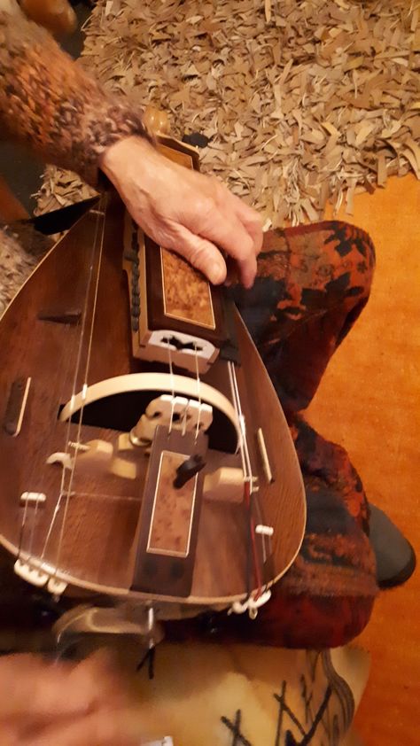 ... Makes tuning the single tones much easier for me.
Hurdy-Gurdy Fähnchen
thingiverse
Those are the "Fähnchen" in 3 sizes for my Hurdy-Gurdy (Gothische Kastenleier). They might not fit in yours but they are easy to design and also easy to print. If someone knows how the "Fähnchen" are called in English, please let me know. ... ...
hurdy gurdy toy
thingiverse
Salut, une petite vielle au format STL.
hurdy gurdy keyring
thingiverse
Hi, hurdy gurdy in 3D printing . ...Enjoy
Hurdy Gurdy (Sea of Thieves)
thingiverse
Sea of Thieves hurdy gurdy, takes a cheap 20 note music box (just the cheap ones you see on ebay etc) UPDATE** Uploaded hurdyBODY1 & 2 for people with smaller printbeds. Video of it playing: https://www.youtube.com/watch?v=mM8mb9U5M1w Feel...
DigiGurdy: electronic hurdy-gurdy keybox
thingiverse
Updates:
Some .stl files and Build / User instructions updated on 10/03/2019
Extra notes added on which OLED screens to buy. They are not all the same! 31/05/19
Extra notes on the various pin labels used by different OLED displays. 31/05/19
...
31/05/19
...
FUNCTIONAL 3D Printable Hurdy Gurdy
thingiverse
This is a fully 3D printable and Functional Hurdy Gurdy that i have designed. The majority of this project uses tight tolerances, so i recommend printing the HG Tolerance Test i made specifically for this before printing the Hurdy Gurdy. I made a...
ugears hurdy gurdy repair part
thingiverse
Dear all,
it is a side part for the ugear Hurdy gurdy mechanical toy.
My son broke two of the many parts that are holding the front and backside together... by letting it falling down.
as the part is a non exact copy of the original, I just. ..
..
ugears hurdy gurdy repair part
prusaprinters
<p>Dear all,</p> <p>it is a side part for the ugear Hurdy gurdy mechanical toy.<br/> My son broke two of the many parts that are holding the front and backside together... by letting it falling down.<br/> as the part is a non exact copy of the...
Musical instrument Hurdy Gurdy 3D model
cgtrader
Model musical instrument Hurdy Gurdy. The model is located in zero coordinates, high-resolution textures are used. I hope you will enjoy! Pleasant to use! Hurdy-Gurdy - string frictional musical instrument. It is found among many peoples, including...
Alto Hurdy Gurdy “Jiri” by Graeme McCormack
grabcad
This is a full 1:1 modelling of a hurdy gurdy I designed and made back in 2008. ...Other details on the actual Hurdy Gurdy can be seen at AntiQuated Strings https://sites.google.com/site/mccormackgraeme/antiquatedstrings
$5.00The Mini Giddy Hurdy Gurdy
myminifactory
The Mini Giddy! The World's first fully 3D printed hurdy gurdy, and the World's smallest functional Hurdy Gurdy. The hurdy gurdy is a classic instrument used in Medieval times, with it's unique design and sound. The Mini Giddy uses the same concepts...
Hurdy Gurdy Hieronymus Bosch Low-poly 3D model
cgtrader
Hurdy Gurdy, built after the Hurdy Gurdy in Hieronymus Bosch's Paintings Medieval stringed instruments of bards and minstrels comes with diffuse and AO maps
Hurdy Gurdy Hieronymus Bosch Low-poly 3D model
cgtrader
Hurdy Gurdy, built after the Hurdy Gurdy in Hieronymus Bosch's Paintings Medieval stringed instruments of bards and minstrels
Nerdy Gurdy - V6
thingiverse
The Open Source Gurdy Project
A few years ago I took up the idea of building my own Hurdy Gurdy.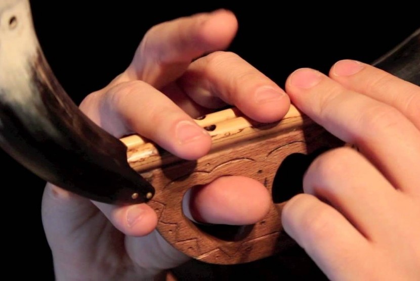 Now I’m not much of a craftsman, so that might be a disadvantage. I am, however, a highly experienced mechanical engineer. My normal field is...
Nerdy Gurdy String Support
thingiverse
This piece replaces the wire terminals in the Nerdy Gurdy build. This is NOT my design, but I cannot find it on this site, and other users are interested in using it, so I uploaded. ...I cannot remember who made it, so I cannot give them credit.
Nerdy Gurdy String Holder
thingiverse
This is an improved string holder I designed for the Nerdy Gurdy 6.2. I wanted something that looked nicer than the prescribed ring terminals, and a one piece design like this better distributes the forces from the strings. Its designed to use #6...
Nerdy Gurdy v6.3
thingiverse
v6.3 of the Nerdy Gurdy Assembler (NGA). ... Changes in v6.1 • Dual strap pins added • Bridge updated to increase volume • Old version of drone bridge removed • Redundant plate removed from lid assembly • Tangents changed to...
Nerdy Gurdy wheel cover
thingiverse
Just some over-engineered plastic tabs to hold a piece of 1.5mm veneer in place.
Nerdy Gurdy - V5
thingiverse
<b>note: V6 released at: https://www. thingiverse.com/thing:3575109</b>
The Open Source Gurdy Project
A few years ago I took up the idea of building my own Hurdy Gurdy. Now I’m not much of a craftsman, so that might be a disadvantage. I am,...
thingiverse.com/thing:3575109</b>
The Open Source Gurdy Project
A few years ago I took up the idea of building my own Hurdy Gurdy. Now I’m not much of a craftsman, so that might be a disadvantage. I am,...
Nerdy Gurdy Bits
thingiverse
Wheels for Nerdy Gurdy 6.1 - mix of hub socket and threaded - also shims for the keybox 1 thru 5mm.
Nerdy Gurdy crank
thingiverse
New crank/ knob design for the Nerdy Gurdy, as introduced with the Nerdy Gurdy BASIC https://www.nerygurdy.nl/
Nerdy Gurdy v6. 1
1
thingiverse
The Open Source Gurdy Project A few years ago I took up the idea of building my own Hurdy Gurdy. Now I’m not much of a craftsman, so that might be a disadvantage. I am, however, a highly experienced mechanical engineer. My normal field is...
Nerdy Gurdy Side Plate
thingiverse
I couldn't find anyone that made this model. So here it is. ...Haven't printed it yet but it should be exact to the curve of the model according to Fusion 360.
▷ hurdy gurdy 3d models 【 STLFinder 】
FUNCTIONAL 3D Printable Hurdy Gurdy
thingiverse
This is a fully 3D printable and Functional Hurdy Gurdy that i have designed. The majority of this project uses tight tolerances, so i recommend printing the HG Tolerance Test i made specifically for this before printing the Hurdy Gurdy. I made a...
Musical instrument Hurdy Gurdy 3D model
cgtrader
The model musical instrument Hurdy Gurdy was created in 3Ds Max and textured in 3D coat. A standard material without textures has been added to the musical instrument Hurdy Gurdy, all textures are in the zip archive. Previews of the model musical...
Hurdy gurdy 3D model
cgtrader
Blender 2.79
hurdy gurdy keyring
thingiverse
Hi, hurdy gurdy in 3D printing .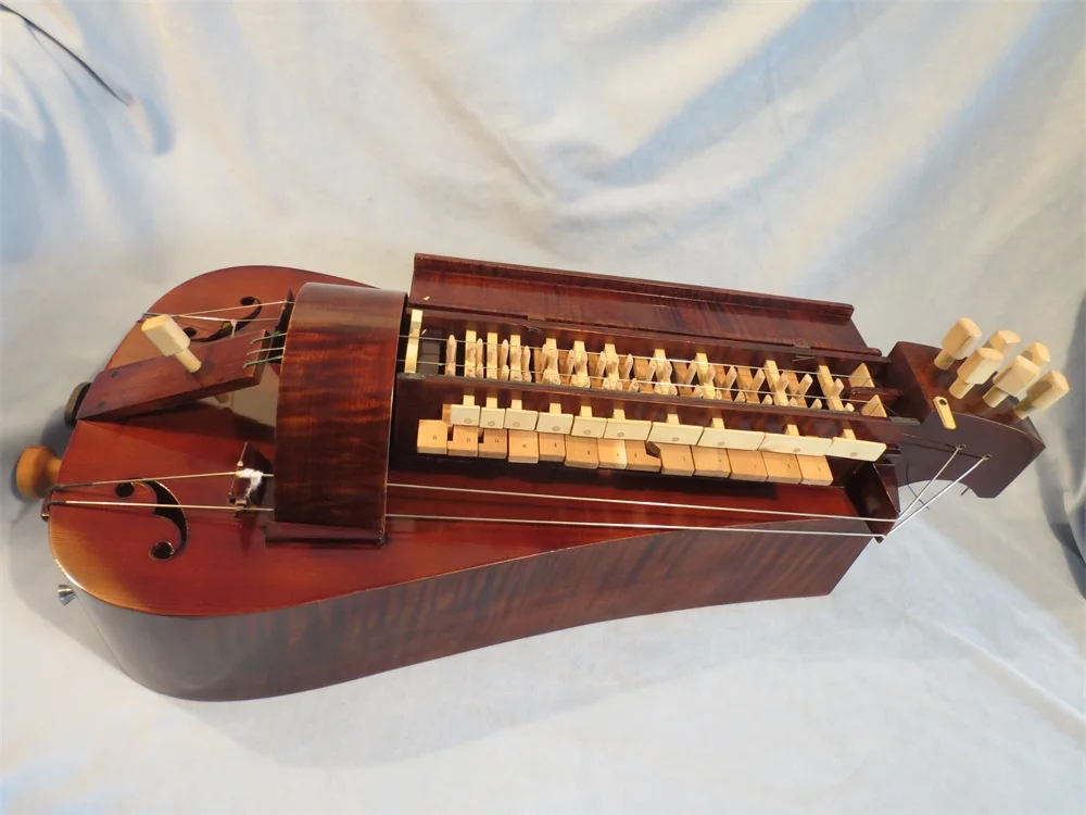 ...Enjoy
Hurdy gurdy key ring
grabcad
traditional musical instrument French for 3d printed key ring
Hurdy Gurdy Hieronymus Bosch Low-poly 3D model
cgtrader
Hurdy Gurdy, built after the Hurdy Gurdy in Hieronymus Bosch's Paintings Medieval stringed instruments of bards and minstrels
Hurdy Gurdy Hieronymus Bosch Low-poly 3D model
cgtrader
Hurdy Gurdy, built after the Hurdy Gurdy in Hieronymus Bosch's Paintings Medieval stringed instruments of bards and minstrels comes with diffuse and AO maps
ugears hurdy gurdy repair part
prusaprinters
The model made by Ugears is counting many many other parts. Copying it in such a way that you will be able to reconstruct a 3d Printed version (with a high fidelity) will be an infringement so don t do that. One point more: I had a lot of fun...
ugears hurdy gurdy repair part
thingiverse
Copying it in such a way that you will be able to reconstruct a 3d Printed version (with a high fidelity) will be an infringement so don t do that. One point more: I had a lot of fun mounting the Ugear toy- I also modified it to add a buzzing...
DigiGurdy: electronic hurdy-gurdy keybox
thingiverse
The entire structure is 3D printed. Although there are a lot of parts these have been broken down into manageable modular sections. The keys press on microswitches and the brain of the device is an Arduino Teensy 3.6 microcontroller. An OLED display...
$5.00The Mini Giddy Hurdy Gurdy
myminifactory
The World's first fully 3D printed hurdy gurdy, and the World's smallest functional Hurdy Gurdy. The hurdy gurdy is a classic instrument used in Medieval times, with it's unique design and sound. The Mini Giddy uses the same concepts of larger full...
hurdy gurdy
grabcad
The hurdy gurdy or hurdy-gurdy is a stringed musical instrument that produces sound by a crank-turned rosined wheel rubbing against the strings. The wheel functions much like a violin bow, and single notes played on the instrument sound similar to a...
Hurdy Gurdy
sketchfab
If you’re unfamiliar with what this is, it’s basically a stringed instrument, similar to a violin. However, instead of a bow, the musician turns a crank that bows the strings, and then uses the keys on the side to play the melody. The song you hear...
Nerdy / Hurdy Gurdy Knob
thingiverse
Traditional sized knob for Nerdy Gurdy, to use with M8 threaded rod, this does not need any bearings, the stud is locked onto the crank with two nuts, this knob it then fixed using a washer and nyloc nut to allow free movement.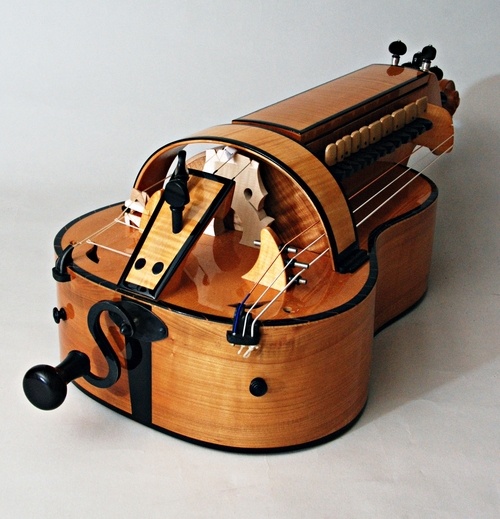 ...The bush will allow...
Dragon Hurdy-Gurdy
sketchfab
A cartoon hurdy-gurdy with a little touch of dragon
hurdy gurdy toy
thingiverse
Salut, une petite vielle au format STL.
Hurdy-Gurdy Fähnchen
thingiverse
Those are the "Fähnchen" in 3 sizes for my Hurdy-Gurdy (Gothische Kastenleier).
They might not fit in yours but they are easy to design and also easy to print.
If someone knows how the "Fähnchen" are called in English, please let me know. ...
...
...
...
Hurdy Gurdy tuning wrench
thingiverse
This is a tuning wrench for the "Fähnchen" within my hurdy gurdy. ... Makes tuning the single tones much easier for me.
Hurdy Gurdy (Sea of Thieves)
thingiverse
Sea of Thieves hurdy gurdy, takes a cheap 20 note music box (just the cheap ones you see on ebay etc) UPDATE** Uploaded hurdyBODY1 & 2 for people with smaller printbeds. Video of it playing: https://www.youtube.com/watch?v=mM8mb9U5M1w Feel...
Nerdy Gurdy V6 3D Printable
thingiverse
These are the laser cut profiles converted to STL. This has not been tested fully. I am not going to add ungrouped or edited versions. I will be uploading a separate remix with my custom redesign.
...
More info on the Nerdy Gurdy:...
This has not been tested fully. I am not going to add ungrouped or edited versions. I will be uploading a separate remix with my custom redesign.
...
More info on the Nerdy Gurdy:...
Alto Hurdy Gurdy “Jiri” by Graeme McCormack
grabcad
This is a full 1:1 modelling of a hurdy gurdy I designed and made back in 2008. ...Other details on the actual Hurdy Gurdy can be seen at AntiQuated Strings https://sites.google.com/site/mccormackgraeme/antiquatedstrings
3D Models
grabcad
3D
3D MODELS
grabcad
3D WORK
3D models
grabcad
3D models
3d models
grabcad
designed in 3d
3D MODELS
grabcad
MADE VARIOUS 3D MODELS OF COMPONENTS USING CREO
3d models 3D model
cgtrader
3d model
3d models 3D model
cgtrader
3D table model
3d models 3D model
cgtrader
hello,.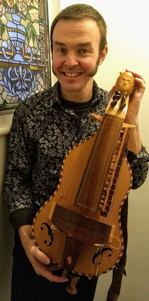 ...my name is sourabh chopra . i am a 3d artist. i have 3 years experience in 3d modelling. ...
3d models 3D model
cgtrader
There is file of some 3d models of Railway Station View, Bike and Street view with texturing and camera animation. ...
Arduino barrel organ / Sudo Null IT News
This publication is a translation of my instructions posted on instructables.com. The project won first place in the DIY Arduino contest 2020 by Instructables
Hello! This is an article about how I made a hurdy-gurdy on Arduino.
Demo
A bit of history
The idea of automatic musical instruments is not new. People have always tried to automate various musical instruments, including the piano.
From the middle of the 18th century until the invention of the gramophone, various automatic instruments existed. These were mainly pianolas and manual street hurdy-gurdies. These tools were automated by mechanics and pneumatics.
The mechanical design used a cam driven roller. Rotating, the cams touched the hammers, which corresponded to the keys of the piano.
At the end of the 19th and beginning of the 20th centuries, more advanced tools appeared, controlled by means of perforated paper tapes. Such instruments used a pneumatic circuit with bellows and pipes, and the holes in the tape played the role of miniature pneumatic valves.
Reading notes
First you need to determine whether the piano key is pressed or not.
Ancient musical instruments use rather complex mechanisms. I can use Arduino and electronic sensors to determine if a key is pressed or not. For example, using an IR sensor or a line sensor. These sensors are widely used in the Arduino world for line racing. They allow you to determine whether the surface under them is white or black.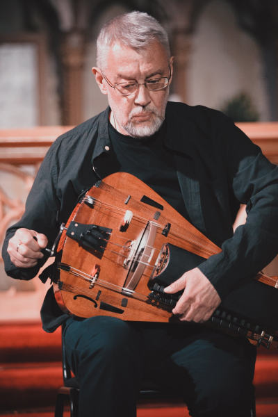
The idea is the following. Let one IR sensor represent one note and a piano key. There are several sensors. A sheet of paper divided into parallel tracks is placed under the sensor. Tracks consist of black and white areas. The sheet starts moving relative to the sensors. If there is a black area on the track under the sensor, then the key is pressed. If the area is white, the key is released. At the moment when the key passes from the released state to the pressed one, the note starts to sound. The sound is held as long as the area under the sensor remains black.
Using several line sensors at the same time, you can create a kind of electronic piano keyboard, where each sensor corresponds to its own key and note. By arranging black and white areas on a sheet in a certain way and moving the sheet at the right speed, a sequence of notes in a piece of music can be obtained.
I made a keyboard with 40 keys. For this I used five Octoliner modules. The Octoliner module is an eight-channel line sensor. Each module has eight TCRT5000 optocouplers and can be used for 8 different piano keys. The module is controlled by the I2C bus, and it is easy to communicate with the Arduino.
I placed five modules in series to create a single large linear array of 40 (5x8) sensors. You can make a keyboard with fewer keys, or you can make a full size piano keyboard with 88 keys. I chose 40 because that's about half of the keys on a real instrument.
Arduino as midi device
I use Arduino to read signals from all linear sensors. However, the sensors are only capable of informing the Arduino whether a key is pressed or released. In order to get sound at the end, you need to turn Arudino into a MIDI device.
MIDI is a universal digital recording standard for exchanging data between various musical instruments. MIDI devices exchange messages. These messages contain information about the keys pressed, their volume and tone.
The Arduino is capable of translating keystrokes into MIDI messages. I chose an Arduino board that is capable of emulating a USB HID device. By transmitting MIDI messages via the USB port, Arduino turns into a real electronic piano keyboard. With a USB MIDI device, I will be able to extract sound using a synthesizer by simply plugging the Arduino into the computer's USB port.
The choice fell on the Arduino MKR ZERO board. It is capable of emulating USB HID out of the box. The board is very productive, and its large amount of flash is ideal for storing heaps of music presets. I also used a regular tact switch to switch presets and a 16x2 I2C LCD character-generating display to show the current preset.
Construction of the barrel organ
I will not describe the entire construction in detail. The hurdy-gurdy was made the first time and at random. Just for the sake of experiment. There are quite a lot of details here, it's easier to look at the 3D model and specification. I used plexiglass, laser cutting, 3D printing, and materials and mechanics that I had at home to make the parts.
- Barrel piano BOM;
- CAD 3D model.
I conditionally divided the design into two main parts and called them "rectifier" and "puller". Both parts are attached to the base plate. The straightener is fixed to the base with 65mm M3 studs, and the puller is fixed with printed corners. Fasteners are not shown on the assemblies, but are in the specification.
Rectifier assembly
Rectifier aligns paper music sheet with sheet music before reading and has line sensors installed. The sheet for forty sensors came out wide. Such a sheet can bend and tear during movement. Each note track on the sheet must be directly below the corresponding optocoupler. Therefore, the music sheet must be aligned before reading.
The rectifier is assembled from several plates. The paper sheet is sandwiched between the base and the lid. A small gap of 1-2 mm is made between the lid and the sheet so that the sheet does not bite when moving. Two guide plates are installed on the sides. Five line sensor modules are mounted on a plate at a certain height above the sheet and are attached to the base with four 6mm posts.
Stripper Assembly
This part is for feeding the sheet. She pulls a sheet from the straightener.
Four wheels with rubber rings are mounted on the shafts. They tightly clamp the music sheet. Rotating, these wheels pull the read sheet out of the straightener. The puller is fixed on the base plate with corners. The puller consists of three Plexiglas plates and three 6mm shafts between them. Shafts are fixed in plates with F626ZZ flanged bearings. The bearings are fixed with printed caps.
The shafts are rotated by a flywheel through a belt drive. I used a 2GT belt with no tension. Closed-loop belt 6mm wide with 250 teeth. Such belts and pulleys for them are common in hobby CNC machines and 3D printers, so they are easy to find and buy. Small pulley - purchased GT2 20 6 B6.
Larger pulley homemade, laser cut from Plexiglas. It consists of 4 plates with a thickness of 2 and 4 mm and an aluminum flange for a 6 mm shaft.
Flywheel consists of Plexiglas plate, F625ZZ bearing, 6mm shaft flange and printed handle. The bearing is pressed onto the handle and fixed in the plate with a printed cap.
The wheels pulling the sheet are also prefabricated. Each wheel consists of 4 plates, 3 and 2 mm thick, and a flange for a 6 mm shaft. A rubber o-ring is stretched over the plates. I used a regular o-ring GOST 9833 050-060-58.
Shielding of optocouplers
There are many optocouplers in the barrel organ and they are located very close to each other. With the simultaneous operation of many sensors, their signals can be repeatedly reflected and intersect with each other, which will lead to significant errors in the received data.
I decided to get rid of interference as much as possible, and shielded each optocoupler with a cap. The caps that fit the TCRT5000 optocouplers are very small, I printed them on photopolymer.
Music sheet translation
Preparing a music sheet is perhaps the most tedious task, especially if you are not familiar with musical notation.
So, one line sensor has 8 channels responsible for reading 8 notes. The length of the sensor is 80mm. By placing 5 modules side by side, I get a total length of 400mm. I will add another 5mm of free space around the edges. Thus, the total width of the music sheet is 410 mm.
The width of one note track is equal to the width of one optocoupler and is 5.8mm. The distance between the optocouplers on the sensor is 4.2 mm. The same distance between the note tracks on the sheet.
Notes are divided by duration, where duration is a fraction of a bar. A note can be a whole, half, fourth, eighth, sixteenth, etc. As a basis, I take the duration of the sixteenth note, and assign it a height of 10mm on the sheet. Now the entire sheet can be lined with horizontal lines at 10mm intervals, as this is the minimum step. A 10x5.8mm black rectangle on a track will produce a sixteenth-note sound. A rectangle with a height of 20mm is the eighth, 40mm is the fourth, 80mm is half, 160mm is the whole.
In MIDI format, each note on the piano keyboard has a unique number. These numbers will be assigned to the line sensor channels. When transcribing for myself, I formed a few steps so as not to get confused. I will show on the example of a simple melody "rain rain go away" (c) www.teaching-children-music.com.
- Look at all the notes that are used in a piece of music and write down their MIDI numbers in ascending order. This tune uses only three notes of the first octave: E, G and A. Note E of the first octave is MIDI number 64, G is number 67, and A is number 69.
- Assign MIDI numbers to line sensor channels. For example, I assign the first channel number 64, the second channel number 67 and the third number 69.
- Look at the size of the work. This tune is in 2/4 time. This means that the length from one bar to the next is two notes with a fourth duration. Thus, the height of one measure on the sheet is 40 mm (2 * 80 mm). A complete melody has 4 bars and I can fit all the bar lines.
- We translate the work. We paint over rectangular black areas on the sheet in accordance with the duration of the notes.
- Correcting the music sheet and removing blots. For example, this melody has two identical eighth notes that sound sequentially in the second, third and fourth measures. On the translated fragment, these two eighth notes have merged into a single fourth note. They must be separated by slightly shortening the duration of the first note. To do this, we reduce the height of the first rectangle, providing an empty white gap.
Translated music
The entire score is too long to physically fit on one sheet of paper. To fit all the notes, I printed them out in parts on several sheets of A1. Then I cut the edges of the sheets to the desired width and glued them sequentially into one large roll. In total, I tried to translate three pieces of music.
- "Hedwig's Theme" from Harry Potter, arranged by Patrick Piesman.
MIDI notes used:
41, 42, 43, 45, 48, 49, 50, 52
54, 55, 56, 58, 59, 60, 61, 62
63, 64, 65, 66, 67, 68, 69, 70
71, 72, 73, 74, 75, 76, 77, 78
79, 80, 81, 82, 83, 84, 85, 86 - "The Black Pearl" from Pirates of the Caribbean arranged by Klaus Badelt.
MIDI notes used:
31, 33, 34, 36, 38, 40, 41, 43
45, 46, 48, 50, 52, 53, 55, 57
58, 59, 60, 61, 62, 63, 64, 65
66, 67, 68, 69, 70, 71, 72, 73
74, 76, 77, 79, 81, 82, 85, 86 - The original first part of "The Entertainer" by Joplin.
MIDI notes used:
43, 44, 45, 47, 48, 50, 51, 52
53, 54, 55, 56, 57, 58, 59, 60
62, 63, 64, 65, 67, 69, 71, 72
74, 76, 77, 78, 79, 81, 83, 84
86, 87, 88
I am enclosing links to the original piano sheet music, to my translated sheet music for the barrel organ, and a blank lined A1 CAD sheet that may be useful for your translations.
- Translation for hurdy-gurdy "Hedwig's Theme"
- Translation for barrel organ "The Black Pearl"
- Translation for barrel organ "The Entertainer"
- Source "Hedwig's Theme"
- Original "The Black Pearl"
- Source "The Entertainer"
- Ruled sheet CAD
XOD and libraries
I use the XOD visual programming environment to flash the Arduino. I use XOD a lot in my projects and this one is no exception. Moreover, all the libraries necessary for the project have already been created by users.
amperka/octoliner is a library from the manufacturer for working with an eight-channel line sensor. It contains all the necessary nodes to quickly get started with the sensor, as well as some nodes for advanced functionality, such as adjusting the brightness / sensitivity of optocouplers or changing the I2C address.
-
e/midi -
e/usb midi -
e/serial midi
These are cool custom XOD libraries that allow you to work with the MIDI format. Library
 e/midi is used to create MIDI messages. Using the e/serial-midi/ and e/usb-midi/ libraries, you can exchange MIDI messages via the serial interface or the Arduino USB port.
The main project patch is in the library gabbapeople/barrel-organ/
Project patch
The hurdy-gurdy patch starts with the initialization of the sensors. Quickstart nodes 9 are used to initialize sensor devices0206 octoliner from library amperka/octoliner . Each device has its own I2C address. The line sensor address can be changed using the example in the library amperka/octoliner . For each sensor node set-brightness sets the brightness of the IR emitters to 1 . Then node set-sensitivity sets the sensitivity of the IR receivers to 0.9 . Separate busbars for five devices DEV1 , DEV2 , DEV3 , DEV4 , DEV5 .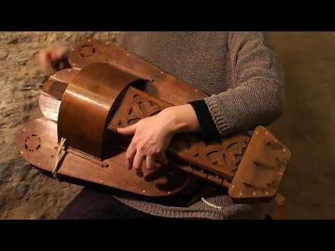 The
The usb-midi-device node creates and stores an instance of the MIDI custom type used to generate and send MIDI messages. There is a delay of 1 second when power is applied. After the parameters of all sensors are initialized, node gate starts to pass continuous pulses through itself.
The program has a preset counter. Each preset corresponds to a specific set of MIDI notes assigned to line sensor channels. Presets are switched with button and node track-charger . The display text-lcd-i2c-16x2 shows which preset is currently active.
Next comes node keyboard . This node accepts the busses of all sensors, bus MIDI , as well as the current value of the preset counter.
Keyboard node
Node keyboard is composite and very large, it is the heart of the device. The structure of a node starts with the sensor buses and the value of the current preset.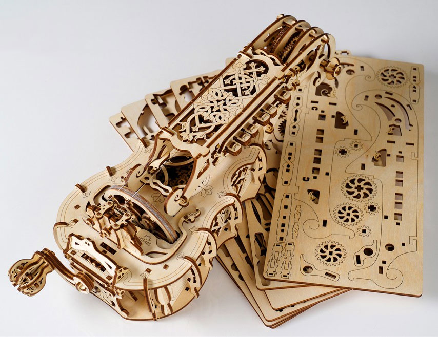
Five nodes follow octoliner-read-channels . One such node reads eight analog signals from eight optocouplers on the sensor. The signals are read sequentially and digitized using a simple formula. If signal >=0.7 , then the key is pressed; if not, then she is released. In total, the nodes octoliner-read-channels have 40 output pins numbered from CH0 to CH7 and output 40 boolean values in them.
Next comes the MIDI note number selection based on the preset. One channel can correspond to different notes. The choice of note for a particular channel depends on the current preset. Noda note-switcher selects the desired MIDI number depending on the preset number. Each note is assigned a bus with a unique name, for example - 48_1 , where the first value is the MIDI number, and the second value is the preset number. Logic nodes xor cut off unused buses.
Sorted MIDI number buses go to nodes octave . In total, I made six "octave" nodes from 1 to 6. These nodes correspond to the six octaves of a real piano. Each node
 octave consists of twelve boolean input pins for twelve MIDI note numbers. For example, for the fourth octave, the input pins will be MIDI numbers 60, 61, 62, 63, 64, 65, 66, 67, 68, 69, 70, 71. MIDI message via USB port.
Sound output
The barrel organ can be connected to any synthesizer with USB. For example, you can connect it to a Windows computer and use Synthesia. Or connect it to raspberry and use QjackCtl & Qsynth.
Arduino hurdy-gurdy
This publication is a translation of my instructions posted on instructables.com. The project won first place in the DIY Arduino contest 2020 by Instructables
Hello! This is an article about how I made a hurdy-gurdy on Arduino.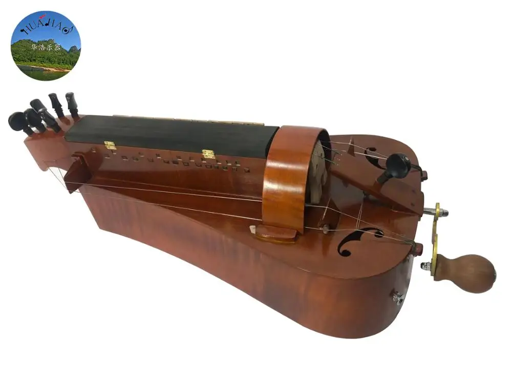
Demo
A bit of history
The idea of automatic musical instruments is not new. People have always tried to automate various musical instruments, including the piano.
From the middle of the 18th century until the invention of the gramophone, various automatic instruments existed. These were mainly pianolas and manual street hurdy-gurdies. These tools were automated by mechanics and pneumatics.
The mechanical design used a cam driven roller. Rotating, the cams touched the hammers, which corresponded to the keys of the piano.
At the end of the 19th and beginning of the 20th centuries, more advanced tools appeared, controlled by means of perforated paper tapes. Such instruments used a pneumatic circuit with bellows and pipes, and the holes in the tape played the role of miniature pneumatic valves.
Reading notes
First you need to determine whether the piano key is pressed or not.
Ancient musical instruments use rather complex mechanisms. I can use Arduino and electronic sensors to determine if a key is pressed or not. For example, using an IR sensor or a line sensor. These sensors are widely used in the Arduino world for line racing. They allow you to determine whether the surface under them is white or black.
The idea is the following. Let one IR sensor represent one note and a piano key. There are several sensors. A sheet of paper divided into parallel tracks is placed under the sensor. Tracks consist of black and white areas. The sheet starts moving relative to the sensors. If there is a black area on the track under the sensor, then the key is pressed. If the area is white, the key is released. At the moment when the key passes from the released state to the pressed one, the note starts to sound. The sound is held as long as the area under the sensor remains black.
Using several line sensors at the same time, you can create a kind of electronic piano keyboard, where each sensor corresponds to its own key and note. By arranging black and white areas on a sheet in a certain way and moving the sheet at the right speed, a sequence of notes in a piece of music can be obtained.
I made a keyboard with 40 keys. For this I used five Octoliner modules. The Octoliner module is an eight-channel line sensor. Each module has eight TCRT5000 optocouplers and can be used for 8 different piano keys. The module is controlled by the I2C bus, and it is easy to communicate with the Arduino.
I placed five modules in series to create a single large linear array of 40 (5x8) sensors. You can make a keyboard with fewer keys, or you can make a full size piano keyboard with 88 keys. I chose 40 because that's about half of the keys on a real instrument.
Arduino as midi device
I use Arduino to read signals from all linear sensors.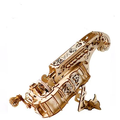 However, the sensors are only capable of informing the Arduino whether a key is pressed or released. In order to get sound at the end, you need to turn Arudino into a MIDI device.
MIDI is a universal digital recording standard for exchanging data between various musical instruments. MIDI devices exchange messages. These messages contain information about the keys pressed, their volume and tone.
The Arduino is capable of translating keystrokes into MIDI messages. I chose an Arduino board that is capable of emulating a USB HID device. By transmitting MIDI messages via the USB port, Arduino turns into a real electronic piano keyboard. With a USB MIDI device, I will be able to extract sound using a synthesizer by simply plugging the Arduino into the computer's USB port.
The choice fell on the Arduino MKR ZERO board. It is capable of emulating USB HID out of the box. The board is very productive, and its large amount of flash is ideal for storing heaps of music presets.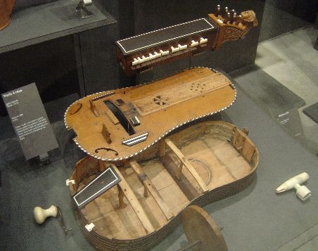 I also used a regular tact switch to switch presets and a 16x2 I2C LCD character-generating display to show the current preset.
Construction of the barrel organ
I will not describe the entire construction in detail. The hurdy-gurdy was made the first time and at random. Just for the sake of experiment. There are quite a lot of details here, it's easier to look at the 3D model and specification. I used plexiglass, laser cutting, 3D printing, and materials and mechanics that I had at home to make the parts.
- Barrel piano BOM;
- CAD 3D model.
I conditionally divided the design into two main parts and called them "rectifier" and "puller". Both parts are attached to the base plate. The straightener is fixed to the base with 65mm M3 studs, and the puller is fixed with printed corners. Fasteners are not shown on the assemblies, but are in the specification.
Rectifier assembly
Rectifier aligns paper music sheet with sheet music before reading and has line sensors installed. The sheet for forty sensors came out wide. Such a sheet can bend and tear during movement. Each note track on the sheet must be directly below the corresponding optocoupler. Therefore, the music sheet must be aligned before reading.
The rectifier is assembled from several plates. The paper sheet is sandwiched between the base and the lid. A small gap of 1-2 mm is made between the lid and the sheet so that the sheet does not bite when moving. Two guide plates are installed on the sides. Five line sensor modules are mounted on a plate at a certain height above the sheet and are attached to the base with four 6mm posts.
Stripper Assembly
This part is for feeding the sheet. She pulls a sheet from the straightener.
Four wheels with rubber rings are mounted on the shafts. They tightly clamp the music sheet. Rotating, these wheels pull the read sheet out of the straightener. The puller is fixed on the base plate with corners. The puller consists of three Plexiglas plates and three 6mm shafts between them. Shafts are fixed in plates with F626ZZ flanged bearings. The bearings are fixed with printed caps.
The shafts are rotated by a flywheel through a belt drive. I used a 2GT belt with no tension. Closed-loop belt 6mm wide with 250 teeth. Such belts and pulleys for them are common in hobby CNC machines and 3D printers, so they are easy to find and buy. Small pulley - purchased GT2 20 6 B6.
Larger pulley homemade, laser cut from Plexiglas. It consists of 4 plates with a thickness of 2 and 4 mm and an aluminum flange for a 6 mm shaft.
Flywheel consists of Plexiglas plate, F625ZZ bearing, 6mm shaft flange and printed handle. The bearing is pressed onto the handle and fixed in the plate with a printed cap.
The wheels pulling the sheet are also prefabricated. Each wheel consists of 4 plates, 3 and 2 mm thick, and a flange for a 6 mm shaft. A rubber o-ring is stretched over the plates. I used a regular o-ring GOST 9833 050-060-58.
Shielding of optocouplers
There are many optocouplers in the barrel organ and they are located very close to each other. With the simultaneous operation of many sensors, their signals can be repeatedly reflected and intersect with each other, which will lead to significant errors in the received data.
I decided to get rid of interference as much as possible, and shielded each optocoupler with a cap. The caps that fit the TCRT5000 optocouplers are very small, I printed them on photopolymer.
Music sheet translation
Preparing a music sheet is perhaps the most tedious task, especially if you are not familiar with musical notation.
So, one line sensor has 8 channels responsible for reading 8 notes. The length of the sensor is 80mm. By placing 5 modules side by side, I get a total length of 400mm. I will add another 5mm of free space around the edges. Thus, the total width of the music sheet is 410 mm.
The width of one note track is equal to the width of one optocoupler and is 5.8mm. The distance between the optocouplers on the sensor is 4.2 mm. The same distance between the note tracks on the sheet.
Notes are divided by duration, where duration is a fraction of a bar. A note can be a whole, half, fourth, eighth, sixteenth, etc. As a basis, I take the duration of the sixteenth note, and assign it a height of 10mm on the sheet. Now the entire sheet can be lined with horizontal lines at 10mm intervals, as this is the minimum step. A 10x5.8mm black rectangle on a track will produce a sixteenth-note sound. A rectangle with a height of 20mm is the eighth, 40mm is the fourth, 80mm is half, 160mm is the whole.
In MIDI format, each note on the piano keyboard has a unique number. These numbers will be assigned to the line sensor channels. When transcribing for myself, I formed a few steps so as not to get confused. I will show on the example of a simple melody "rain rain go away" (c) www.teaching-children-music.com.
- Look at all the notes that are used in a piece of music and write down their MIDI numbers in ascending order. This tune uses only three notes of the first octave: E, G and A.
 Note E of the first octave is MIDI number 64, G is number 67, and A is number 69.
 - Assign MIDI numbers to line sensor channels. For example, I assign the first channel number 64, the second channel number 67 and the third number 69.
- Look at the size of the work. This tune is in 2/4 time. This means that the length from one bar to the next is two notes with a fourth duration. Thus, the height of one measure on the sheet is 40 mm (2 * 80 mm). A complete melody has 4 bars and I can fit all the bar lines.
- We translate the work. We paint over rectangular black areas on the sheet in accordance with the duration of the notes.
- Correcting the music sheet and removing blots. For example, this melody has two identical eighth notes that sound sequentially in the second, third and fourth measures. On the translated fragment, these two eighth notes have merged into a single fourth note. They must be separated by slightly shortening the duration of the first note.
 To do this, we reduce the height of the first rectangle, providing an empty white gap.
Translated music
The entire score is too long to physically fit on one sheet of paper. To fit all the notes, I printed them out in parts on several sheets of A1. Then I cut the edges of the sheets to the desired width and glued them sequentially into one large roll. In total, I tried to translate three pieces of music.
- "Hedwig's Theme" from Harry Potter, arranged by Patrick Piesman.
MIDI notes used:
41, 42, 43, 45, 48, 49, 50, 52
54, 55, 56, 58, 59, 60, 61, 62
63, 64, 65, 66, 67, 68, 69, 70
71, 72, 73, 74, 75, 76, 77, 78
79, 80, 81, 82, 83, 84, 85, 86 - "The Black Pearl" from Pirates of the Caribbean arranged by Klaus Badelt.
MIDI notes used:
31, 33, 34, 36, 38, 40, 41, 43
45, 46, 48, 50, 52, 53, 55, 57
58, 59, 60, 61, 62, 63, 64, 65
66, 67, 68, 69, 70, 71, 72, 73
74, 76, 77, 79, 81, 82, 85, 86 - The original first part of "The Entertainer" by Joplin.

MIDI notes used:
43, 44, 45, 47, 48, 50, 51, 52
53, 54, 55, 56, 57, 58, 59, 60
62, 63, 64, 65, 67, 69, 71, 72
74, 76, 77, 78, 79, 81, 83, 84
86, 87, 88
I am enclosing links to the original piano sheet music, to my translated sheet music for the barrel organ, and a blank lined A1 CAD sheet that may be useful for your translations.
- Translation for hurdy-gurdy "Hedwig's Theme"
- Translation for barrel organ "The Black Pearl"
- Translation for barrel organ "The Entertainer"
- Source "Hedwig's Theme"
- Original "The Black Pearl"
- Source "The Entertainer"
- Ruled sheet CAD
XOD and libraries
I use the XOD visual programming environment to flash the Arduino. I use XOD a lot in my projects and this one is no exception. Moreover, all the libraries necessary for the project have already been created by users.
amperka/octoliner is a library from the manufacturer for working with an eight-channel line sensor. It contains all the necessary nodes to quickly get started with the sensor, as well as some nodes for advanced functionality, such as adjusting the brightness / sensitivity of optocouplers or changing the I2C address.
-
e/midi -
e/usb midi -
e/serial midi
These are cool custom XOD libraries that allow you to work with the MIDI format. Library e/midi is used to create MIDI messages. Using the e/serial-midi/ and e/usb-midi/ libraries, you can exchange MIDI messages via the serial interface or the Arduino USB port.
The main project patch is in the library gabbapeople/barrel-organ/
Project patch
The hurdy-gurdy patch starts with the initialization of the sensors. Quickstart nodes 9 are used to initialize sensor devices0206 octoliner from library amperka/octoliner . Each device has its own I2C address. The line sensor address can be changed using the example in the library
 amperka/octoliner . For each sensor node set-brightness sets the brightness of the IR emitters to 1 . Then node set-sensitivity sets the sensitivity of the IR receivers to 0.9 . Separate busbars for five devices DEV1 , DEV2 , DEV3 , DEV4 , DEV5 . The usb-midi-device node creates and stores an instance of the MIDI custom type used to generate and send MIDI messages. There is a delay of 1 second when power is applied. After the parameters of all sensors are initialized, node gate starts to pass continuous pulses through itself.
The program has a preset counter. Each preset corresponds to a specific set of MIDI notes assigned to line sensor channels. Presets are switched with button and node track-charger . The display
 text-lcd-i2c-16x2 shows which preset is currently active.
Next comes node keyboard . This node accepts the busses of all sensors, bus MIDI , as well as the current value of the preset counter.
Keyboard node
Node keyboard is composite and very large, it is the heart of the device. The structure of a node starts with the sensor buses and the value of the current preset.
Five nodes follow octoliner-read-channels . One such node reads eight analog signals from eight optocouplers on the sensor. The signals are read sequentially and digitized using a simple formula. If signal >=0.7 , then the key is pressed; if not, then she is released. In total, the nodes octoliner-read-channels have 40 output pins numbered from CH0 to CH7 and output 40 boolean values in them.
Next comes the MIDI note number selection based on the preset. One channel can correspond to different notes. The choice of note for a particular channel depends on the current preset. Noda
 note-switcher selects the desired MIDI number depending on the preset number. Each note is assigned a bus with a unique name, for example - 48_1 , where the first value is the MIDI number, and the second value is the preset number. Logic nodes xor cut off unused buses.
Sorted MIDI number buses go to nodes octave . In total, I made six "octave" nodes from 1 to 6. These nodes correspond to the six octaves of a real piano. Each node octave consists of twelve boolean input pins for twelve MIDI note numbers. For example, for the fourth octave, the input pins will be MIDI numbers 60, 61, 62, 63, 64, 65, 66, 67, 68, 69, 70, 71. MIDI message via USB port.
Sound output
The barrel organ can be connected to any synthesizer with USB. For example, you can connect it to a Windows computer and use Synthesia.