How to use cad for 3d printing
What software to use for 3D printing: The complete guide
David Roberson13 May 2021
Guide
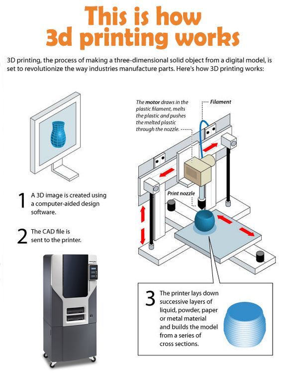
Before starting to 3D print, you will need to make sure you have gathered all the necessary software “ingredients” that will guide you through the printing process, from preparing your 3D model to managing printers themselves.
These include:
CAD software to create a 3D model (you can also use an existing 3D model, if you do not wish or need to design one)
Slicing software
Software to operate your printer remotely (this is optional, but can be convenient)
This article will go through each of these ingredients, and will also touch on how the Ultimaker platform creates a seamless end-to-end flow between hardware, software, and materials, empowering you to unlock the magic of 3D printing and make innovation happen.
What is a “slicer”?
A 3D printing slicer – also known as slicing or print preparation software – is a program that converts a 3D model into a language your 3D printer understands.
Slicing software, such as Ultimaker Cura, digitally cuts a model into flat layers, which your printer can then print one by one. With the Ultimaker platform, however, slicing software is not always needed, thanks to integrations that allow you to print directly from CAD or the Ultimaker Digital Library.
Preparing a 3D print using Ultimaker Cura software
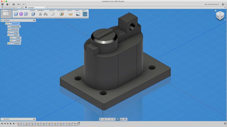
What is the best CAD software to design 3D prints?CAD, or computer-aided design, software enables you to design a 3D model from the ground, up. There are many types of CAD software, each with its own benefits. AutoCAD, created by Autodesk, is perhaps the best-known among them since it was one of the first CAD software programs available for personal computers when released in 1982. Other CAD platforms include:
Fusion360 – great for designing and creating efficient mechanical parts
3ds Max – used in all types of 3D model creation, including video game design, architecture, and 3D printing
TinkerCAD – A free, browser-based CAD tool that allows users to build 3D models out of various shapes.
 Popular with CAD novices and for STEAM education
Blender – free, open-source 3D model creation software
Siemens NX – for designing and creating advanced 3D models
Solidworks – for designing and creating professional parts for industrial use
Catia – Advanced design software used for creating surfaces and engineering systems
Before you begin 3D printing, be sure to do your research and pick the CAD software that’s right for your use case. This way, you’ll get the most out of the model you choose to design and print.
Also check which file types your slicing software is compatible with, so you can make your 3D designs into 3D prints.
A design in CAD software (left screen), slicing software (right), and the finished print
How to design parts for 3D printing?
When designing for 3D printing, there are best practices to help you get the best results from your 3D printer and the parts it creates. Design parts optimized for 3D printing will improve print success rates, reduce costs through lower wastage, and boost the speed of your product development cycle.
Consider build volume. Your 3D prints can only be as large as your printer’s build volume. Be sure to know its dimensions, then create a part that can either be printed within those dimensions in one go, or plan to use modularity (printing then combining separate parts).
Decide orientation early. Because FFF prints layer by layer, determining the print orientation early in the process helps drive design choices, text alignment, and snap features.
Evaluate overhang support requirements. FFF printed parts are self-supporting up to 45 degrees. Overhangs below 45 degrees must be supported from below with support material.
Follow bridging support guidelines. For most basic filaments, FFF printing does not need support when bridging materials within a 10 mm gap.
Pay attention to nozzle size. When designing small features, you should consider height, wall thickness, and nozzle size. Larger nozzles will print faster than smaller nozzles, but at a cost of increased minimum thickness and height for your models.
Design with hole diameters in mind. Generally, 3D printed hole features should not be smaller than 2 mm. If accurate holes are required, it is recommended to design the holes smaller than intended and post-process with a drilling operation.
Avoid sharp corners. Sharp corners can be modelled in CAD, but the print may warp. Increasing the area of the surface in contact with the bed will decrease the likelihood of the warpage.
For a deep dive into these factors and more, check out our blog on design for 3D printing.
What software do I need to start a 3D print?
This depends on how much of the 3D printing workflow you need to perform.
As long as you already have access to a 3D model, you will typically need software that can slice that model, so your printer can get to work. Once you have started to print, you can also use software to manager your 3D printer (or printers) remotely.
But as we saw earlier, the slicing step can be avoided if you have a 3D printer integration installed in your CAD tool. If you already have access to a 3D printable file (such as a G-code on a USB stick) you can also go ahead and print without the need for any slicing software, as your digital file is already ready to print.
Controlling 3D printers remotely with Ultimaker Digital Factory software
Managing 3D printers remotely
Ultimaker S-line printers, the Ultimaker 2+ Connect, and the Ultimaker 3 can make use of a network connection to access cloud-based services on Ultimaker Digital Factory. By linking a printer to your Ultimaker account, your printer can then be controlled remotely, from outside of its local area network.
Want to learn more about 3D printing software?
Download our free white paper, “Important 3D printing software features,” which will help you determine the best 3D printing software for your business needs, as well as examine settings, print profiles, and other features that can help you get the most out of your printing experience.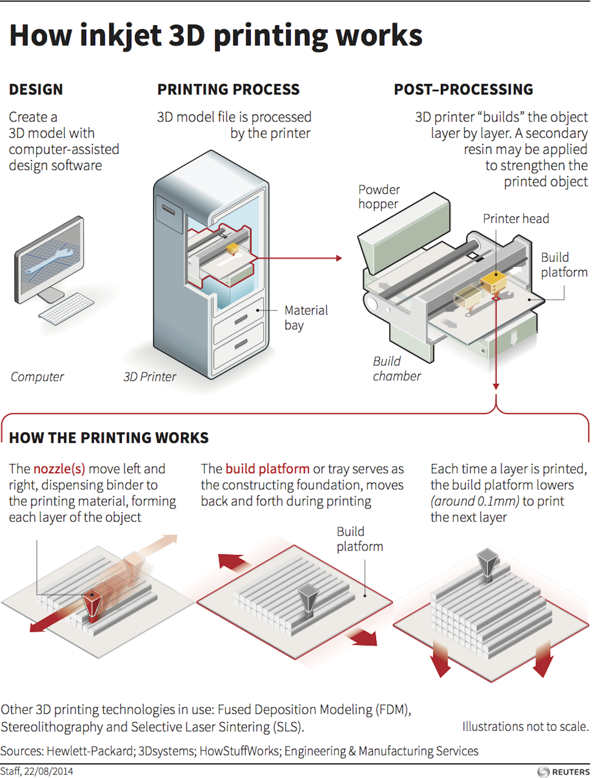
Get the white paper
What is 3D CAD or Computer Aided Design
CAD, or Computer-aided Design, is the use of computer software to assist in the creation, manipulation, analysis, or optimization of a design.
Introduction to 3D CAD
Computer-aided design, or more commonly referred to as CAD, is used to generate virtual 2D or 3D models. 2D CAD designs are generally for technical engineering/architecture, while 3D models are typically either used for digital applications such as animation or for manufacturing and prototyping processes like 3D printing.
What are 3D CAD Software Applications?
CAD 3D modeling is used in an enormous variety of industries. While mainly used for detailed engineering of 3D models or 2D drawings, there are also CAD programs designed specifically for the development of models used in animation and photorealistic rendering! The correct CAD software for you depends upon your application. Check out the links below for examples of available 3D CAD software packages and helpful tutorials on how to use them!
From architecture or sciences to mechanical engineering, fashion or the medical industry, all industries are now seeing the full potential of 3D modeling and making the most of it.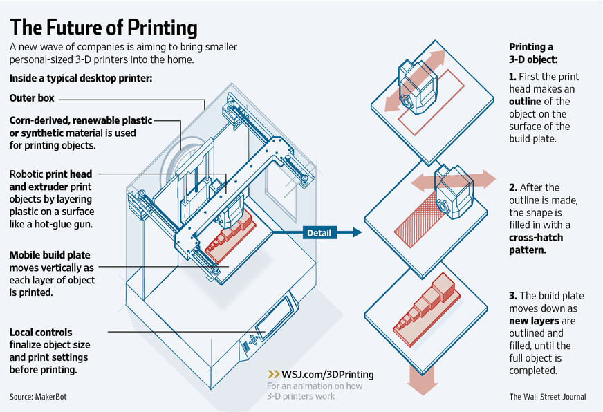 3D modeling can actually be helpful in a lot of different ways: either for rendering, simulation or manufacturing.
Actually, 3D CAD is everywhere. Every modern day product we see or interact with was created using 3D modeling. It means all features and details of your car, your kitchen appliances or living room furniture, your sport equipment, and even your children’s toys, all were first created in a virtual 3D CAD program.
What is the best 3D CAD Software?
Here is a selection of the best 3D CAD software to help you make your choice.
If you’re looking for software that is best for developing models for 3D printing, we suggest trying the CAD modeling software aimed at mechanical or industrial design!
3D CAD Modeling Methods
Each of the above 3D CAD programs utilizes a different method for modeling. Learn more about the types of 3D CAD modeling below!
- Solid Modeling
1. Parametric Modeling: a type of solid modeling that uses 2D sketches to create features and objects that are modifiable with a feature history tree. Features are located and manipulated using geometric and functional relationships with other sketches, features and objects.
2. Direct Modeling: like parametric modeling, direct modeling uses sketches to create 3D features based on relationships with existing geometry. However, there is no history tree, and the original sketch is absorbed into the feature and future edits are made on the resulting geometry.
- Surface Modeling
Another type of modeling that relies on surfaces to generate geometry. Surface modeling can be both parametric (based on geometric and functional relationships) or freeform. Freeform surface modeling is used to manipulate the surface of the model similar to how someone would model with clay. Check out our entries on Sculptris and MeshMixer to learn more about freeform surface modeling!
- Code-driven modeling
This is a growing area of modeling where geometry is generated autonomously based on conditions set in place by the designer.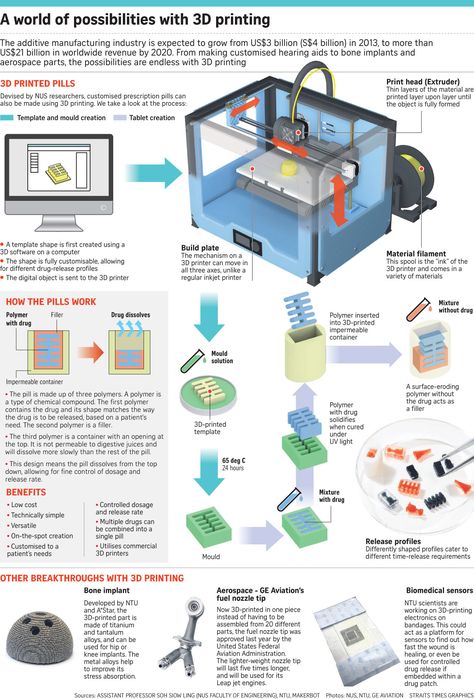 To read more about how this works, check out our entry on Autodesk’s Deamcatcher . This type of modeling is excellent for 3D printing as it can be used to generate 3D structures that can’t be manufactured through any other means.
Prepare for 3D printing!
Related pages
short tips for the transition from a CAD model to a printed object / Sudo Null IT News
was withdrawn from publication due to a technical error. Please be understanding. Thank you!
Whether it's just a hobby or a source of income, 3D printing is always based on product design. Those accustomed to traditional technologies will have to rethink the entire approach to product design and manufacture.
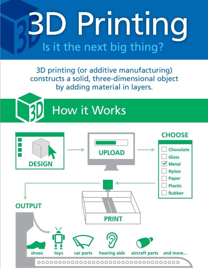
When the project is ready, a number of additional operations are performed: setting the orientation of the model and other parameters that ensure the proper printing process. In addition, it is necessary to take into account the fact that most 3D printers allow you to choose the degree of filling the model with cellular structures.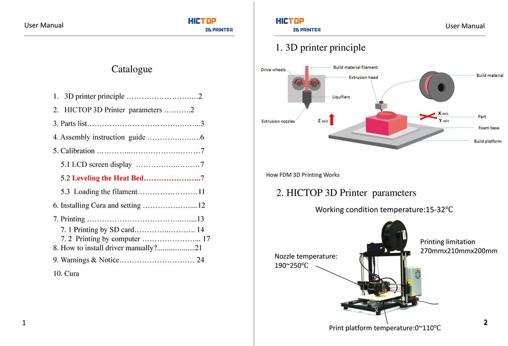 The correct choice of this parameter provides protection of the object from deformation and destruction during the printing process, as well as significant savings in material and reduction in production time.
Finally, the last factor influencing the success or failure of the 3D printing process is the strength of the connection between the model and the table. If the workpiece is separated from the table during printing, then all the work will go down the drain.
Here, we'll walk you through the 3D printing process and give you some simple tips on how to use additive manufacturing in the design phase. In addition, we will dwell on the methods of preparing a finished project for printing, and also consider ways to securely fasten the workpiece to the table.
These guidelines apply primarily to Fused Deposition Printers (FDM) printers, but may apply to other types of printers as well. The process of obtaining a finished part by 3D printing is basically the same regardless of the method used.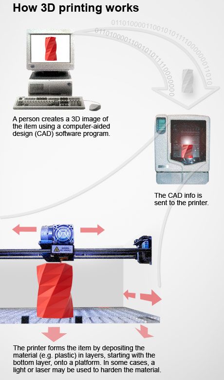
Designing an object
Any 3D printing starts with construction. If you are developing a product yourself, then you need to build a 3D model of it in a computer-aided design (CAD) system to turn the designer's idea into reality. In this case, the object can be both very simple and very complex. However, too thin and too small models should be avoided.
3D-CAD from Siemens from this article for 49900r (90% discount), the promotion is valid until March 20, 2020. Read more>>
Saving the file in a special format for printing
To print an object, its model must be saved in a special file format - for example, STL, which has become the de facto standard in the world of 3D printing. In this format, model surfaces are represented as a grid of triangles. Simple surfaces are broken down into a small number of triangles. The more complex the surface, the more triangles you will need. Today, other formats are used in 3D printing, in particular, the 3MF format developed by Microsoft. But the most common is still STL.
CAD systems make it very easy to save the model in the desired format: just click the Save As command. To improve print quality, it is desirable to set a number of settings for saving to the STL format - for example, the tolerance during transformation and the angle of the plane. The lower the conversion factor and the better the angle, the smoother the printed part will be.
Opening the file in the slicer program
Most, if not all, 3D printers come with their own slicer software. The slicer loads the STL file created in the CAD system and cuts it into layers, and then creates a control program for the printer.
Place the model correctly in the print space
After entering the print settings, the model (or several models) needs to be placed on the printer table. You can print many objects on one table at once. At the same time, compared to printing a single object, the time slightly increases, but in general it still turns out to be less. Here are some tips for choosing the right model orientation.
Set parameters
In the slicer program, the user sets parameters such as print speed, material consumption, nozzle and desktop temperatures. Most slicers have simple settings for beginners. In this case, most often there are also advanced settings so that experienced professionals can achieve optimal results. Advanced settings include percentage infill, amount of backing material, and type of backing or raft (this is a small, thin base that keeps the printed part stable. The backing is removed when it's finished). The number of options is truly endless. Specific settings vary depending on the brand of printer. It's easy enough to set them up.
Sending the control program to the printer
After setting the print settings, the placement of future objects on the table, their orientation and quality, it's time to finally start the printer.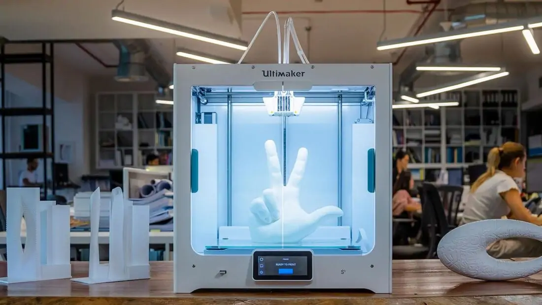 It is enough to press the Print button and find something to do while the production is in progress. Depending on the complexity of the design, the process takes from several minutes to several hours.
Finishing
Finishing includes removing the printed part from the table, as well as removing the support material by melting, mechanical separation or dissolution (depending on the design of the printer). The part may require some light sanding or polishing, but overall a properly printed object looks good from the start. Other types of finishing are placing plastic parts in a container with acetone to smooth out surface roughness, gluing (if the dimensions of the structure exceed the dimensions of the 3D printer or individual elements of the object must have different orientations), drilling holes and painting.
3D printing process
3D printer design considerations
Eliminate sharp corners
If the direction of the surfaces changes abruptly (for example, a vertical wall intersects with a horizontal overlap), then such a model is difficult to print.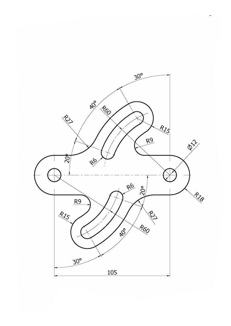 The printer will build excessive inner surfaces, wasting too much material. There are two easy ways to prevent this: add chamfers to smooth out where the surfaces meet, or round the corners so the printer gradually builds a vertical surface. In addition, rounding will increase strength, since destruction most often occurs at sharp corners.
Elimination of thin walls and small geometries
Layer by layer fusing technology consists in supplying hot plastic through a nozzle with the formation of a printed object layer by layer. The thickness of the extruded plastic layer cannot be made smaller than a certain limit, depending on the diameter of the nozzle and the speed of the print head. Excessively thin-walled details are difficult to print - often the result is a chaotic weave of fibers. If the part can be printed, it is very fragile and breaks easily.
Too thick walls - also bad
On the other hand, if the walls are too thick, they become brittle and crack easily.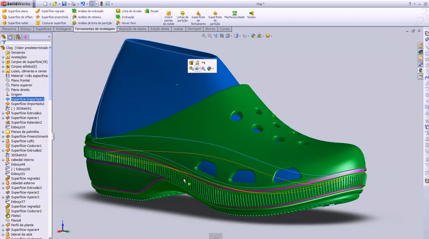 This is especially important when printing from materials other than resins, as excess thickness during the manufacturing process leads to internal stresses in the part. Even when printing from plastics, material is wasted on walls that are too thick and time is wasted.
Removing large overhangs
3D printers allow you to create amazing shapes and surfaces, but they are not capable of printing directly in the air. If there is a void in the part with material above it, additional support material must be used. Most slicers add material automatically, but require you to specify the orientation and volume of the support structure. Printers with a single nozzle create an array of thin columns, which then have to be broken off. The result is an uneven surface. Therefore, it is recommended to avoid large overhanging elements whenever possible in order to reduce the need for support material.
If such an element is unavoidable, you can try to flip the object. Most printers are capable of printing overhanging elements with an angle of about 45 degrees. At a certain height, the edge of such an element may sag somewhat. The actual capabilities of a particular printer are determined by trial and error.
Holes shrink
Remember that the part is made of heated plastic. As it cools, it inevitably shrinks. Therefore, holes and other critical structural elements have to be made larger so that after shrinkage their size is as close as possible to the required one.
However, if you need to make a tight tolerance hole, it is better to print it with a smaller diameter and then ream it with a suitable tool. This is especially true for holes whose axis is parallel to the printer table.
Increasing the footprint
If the area of contact between the object and the base is small, the part may separate from the table during printing. To prevent this from happening, wide bases are added to the model legs, which are installed on the printer table. In general, the closer to the table, the more material must be added to the support. There are other ways to securely fasten the part to the table, which we will discuss a little later.
Special moves
The right approach to design makes printing easier. In addition, there are special post-processing techniques that are important to be aware of.
Place round surfaces vertically
The model should be oriented so that the minimum amount of support material is used. Ideally, it should rest on the table with a large flat edge. In addition, circular geometry must be placed so that the circular faces are vertical. If we look at the printer table from above, we should see a round silhouette of the object. In this case, the part comes out as symmetrical as possible with the formation of a solid round structure.
Place voids and holes vertically
If there are voids in the model (for example, it is a rectangular pipe), it is desirable to place such voids vertically in order to reduce the volume of the support material. If you print the pipe in a horizontal position, you will have to provide support for the entire interior. If you put the pipe on the end, then no support is required at all.
The same is true for holes: to get a hole with a straight axis, it is best to print it vertically - in the form of a stack of rings, which avoids warping or deforming a round hole into an oval one.
Set print quality settings
Proper selection of print parameters, such as STL conversion tolerance and slicer software settings, allows parts to be produced with a surface quality that matches that of cutting. However, this entails an increase in print time. When choosing quality parameters, one should proceed from the purpose of the object: is it a finished product or a prototype? Will the part be visible or hidden?
The quality parameters also affect the shape of the holes in the part. In CAD files, holes are represented as a set of straight lines at an angle to each other. The higher the quality of the model in the saved STL file, the less the circle looks like a polygon.
Reducing the layer thickness
To obtain the best quality, especially when using layer-by-layer deposition technology, it is necessary to reduce the thickness of the layers. It does increase the print time, but the end result is worth it!
Optimizing the filling with honeycomb structures
In terms of strength, objects do not have to be solid. Similar to a honeycomb, printers can create a honeycomb infill that balances strength and saves expensive polymer material. However, if the printed part serves as a prototype for strength testing, and the serial product will be manufactured by traditional methods, and also if the part is subjected to certain types of mechanical stresses and pressures, a solid design will be preferable.
Choosing a material
The success of printing largely depends on the correct choice of material. Materials have different properties. For example, the melting point of thermoplastic polyurethane (TPU) and polylactic acid (PLA) is lower than that of acrylonitrile butadiene styrene (ABS). In addition, the material is taken into account when choosing the type of support structures. For an object made of polylactic acid, supporting elements can be made from the same polylactic acid, since it will be quite easy to separate them from the finished part. If the part is printed from ABS plastic, then the support elements must be made from a different material, and it is better not to use such elements at all in thermoplastic polyurethane parts.
Cellular filling
A solid body is not always the best choice for 3D printing. Printing solid parts has its advantages, but the internal honeycomb structure saves both expensive material and time.
Creating objects with a specified degree of filling with honeycomb structures is a unique opportunity for 3D printing. Moreover, it is not required to design such a structure: this is done by the slicer program. As a rule, it is enough to set only the percentage of filling (the closer it is to 100, the more solid the object will turn out) and select the type of cells, if the printer has such an opportunity.
In addition to saving time and material, the internal honeycomb structure has many other advantages.
Cellular filling prevents warpage
Printing large objects as a single piece introduces a danger of warpage. By reducing the infill percentage, the air during printing passes through the part, providing more uniform cooling and eliminating warping.
Cellular filling does not lead to loss of strength
Printing cells instead of solid material does not reduce the strength of the part. In many cases, a honeycomb part is strong enough for the chosen application, but lighter and less material intensive.
The function determines the choice of cell geometry
Most slicers support a wide variety of cell geometries. The optimal option is determined by the functional purpose of the object. Standard box padding simplifies printing, while hexagonal and triangular boxes add strength. Wave fill allows the object to bend or twist.
How to choose the right filling percentage?
In general, the strength of an object increases as the percentage of infill increases. Most printers have a default infill percentage of 20, which is optimal in some cases but too high or too low in others. Consider mechanical stresses in the printed object and increase the percentage of infill in areas where greater strength is required. If high strength is not required, choose the lowest possible filling. This saves material and speeds up printing. Most often, the selection of the optimal percentage of filling is done by trial and error.
Ways of fastening the workpiece to the table
“Rafts”, “brims”, “skirts” – these terms sound funny, but they just refer to the three main ways of attaching a 3D printed part to a printer table. Let's take a look at each of these methods and their areas of application.
Skirt
The skirt involves creating a few rings around the object at the beginning of the print to make sure the plastic is extruded normally. The skirt is not in contact with the object at all. It surrounds the printable area and helps start the fusing process. When creating a skirt, a large volume of hot thermoplastic polymer passes through the nozzle. This prepares the printer for printing the part itself. This guarantees good adhesion to the table and obtaining smooth surfaces of the object.
Brim
The brim is a wide, flat area connected to the main object as a support base (think of a brim of a hat). It is very similar to a skirt, but connected to the model. In addition to all the advantages of a skirt, the brim keeps the edges of the object being made on the table.
When printing, the outside of an object often cools faster than the middle, causing the edges to curl. Brim prevents this phenomenon by holding the edges.
Raft
A raft is a detachable base, made in the form of a thin mesh platform, located under the entire object (which lies on the raft). To create a raft, the printer first prints a flat plate in two or three layers, and then begins to manufacture the object.
The rafts provide excellent adhesion to the table surface and also provide a strong print base. This is especially useful when making small and oddly shaped parts that do not fit well on the table, as well as thin-walled objects.
After printing is completed, in most cases the raft will separate easily from the part.
If the printer does not have a heated desktop function
Rafts are used if the printer does not have desktop heating.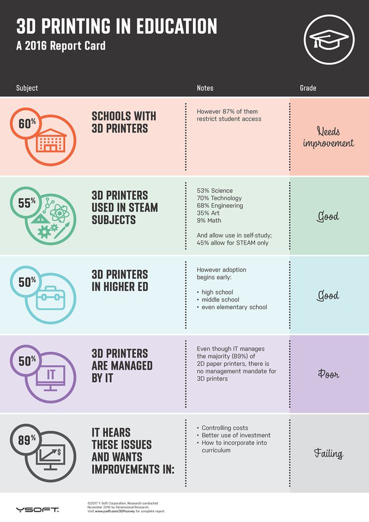 In this case, excessive adhesion becomes a problem.
An alternative method is to apply adhesive paper tape to the printer bed, with the edges down if possible (this also protects the bed). You can also use packing tape, but it is usually more expensive.
If buckling does occur or the object separates from the table, apply a dissolvable glue stick to the adhesive tape. This will enhance adhesion.
Find out the features of a specific 3D printer and take them into account when preparing a model
3D printing is not only a science, but also an art. Effective design for subsequent 3D printing requires an understanding of the technological process, taking into account its features and the purpose of the future object. This will greatly improve print performance.
Using Solid Edge in 3D printing
Not all CAD systems are suitable for 3D printing
The capabilities of the applied system should not limit the designers. Our Solid Edge system is designed with the latest 3D printing technologies in mind. Various 3D printers and 3D printing services are supported.
Take it to the next level with specific techniques for designing 3D printed parts
Generative modeling in Solid Edge opens up new possibilities: the designer selects a specific material, sets the design space, allowable loads, restrictions and target mass of the part, and the system automatically calculates the desired geometry. As a result, 3D printing methods can produce the most complex shapes.
In addition, when building models, the use of the results of three-dimensional scanning is provided. Solid Edge successfully combines the traditional boundary representation of solid models (B-Rep) and the representation of surfaces in the form of a grid of triangles, which avoids time-consuming transformations that are fraught with errors.
If you've already downloaded an STL file for printing, our unique synchronous technology makes it quick and easy to edit your imported models in Solid Edge in preparation for the process.
Printing with your own printer or submitting an order to a 3D printing service provider
Printing in Solid Edge on a local 3D printer is done using the 3D print command. Models can be saved in STL and 3MF formats, or sent directly to Microsoft 3D Builder. If you don't have your own 3D printer or need to try out different materials and surface finishes, Solid Edge allows you to directly submit your models to cloud-based 3D printing services (such as 3YOURMIND). You immediately receive quotes for the production of parts from various materials with its subsequent delivery directly to your door.
3D-CAD from Siemens from this article for 49900r (90% discount), the promotion is valid until March 20, 2020. Read More>>
Using 3D Printing Mockup to Create a Smile Design in One Visit
Summary: 3D printing technologies are constantly evolving and finding more and more applications in various fields of dentistry. 3D printing is increasingly being used as an effective complement to CAD/CAM (computer-assisted design/computer-assisted manufacturing) technologies. This article discusses 3D printing and smile design treatments and presents a case report that describes the process of improving the overall appearance of the upper dentition in a 67-year-old patient. This article also describes the benefits that 3D printing offers clinicians when it is used in the treatment planning process.
3D printing technologies in dentistry help simplify complex processes in traditional treatment. By reducing energy and production costs, 3D printing is often used in dentistry to complement CAD/CAM technologies, increasing efficiency and predictability.
Traditional dental impressions are made with alginate and silicone materials. Further, various orthodontic and orthopedic structures are made on plaster models, such as mouth guards, retainers, crowns, bridges, etc. However, the development of digital technologies has made it possible to use 3D printing for the manufacture of dental structures directly using computer 3D modeling.
The development of digital dentistry has led to the modernization of dental practice, paving the way for automated manufacturing technologies. The integration of 3D printing into dental practice has made it possible to create digital 3D models based on a digital impression obtained from an intraoral scanner (IOS), which are easy to use for diagnosis, treatment planning and computer simulation. Digital models are convenient in that they eliminate the need for storage space, and are also convenient in systematization and communication.
The ability to store digital information has made it possible to create “tooth libraries” that can also be integrated into popular and free software such as the International Digital Dental Academy (www.idda.org), Meshmixer (Autodesk, meshmixer.com).
Clinical case
A 67-year-old man came to the clinic with a desire to replace his old, chipped, stained composite restorations in the upper jaw, as well as whiten his teeth. (Figure 1 and Figure 2). The patient had no history of chronic diseases.
Figure 1. View before treatment
Figure 2. Intraoral view before treatment
On examination, class I occlusion was identified with signs of tooth wear. During sleep, the patient used a mouthguard. After continued motivation and regular professional cleaning, the patient had a good level of oral hygiene with a low risk of developing caries, and the prognosis for any treatment was quite favorable.
Treatment options
The patient wanted to replace all old restorations on the anterior teeth, whether or not they had failed, and also expressed a desire to have veneers on the upper incisors to look younger. The patient also wanted to whiten his teeth in the lower jaw. Thus, the treatment options discussed with the patient were to create new restorations for maxillary incisors, canines and premolars with or without bleaching of the mandibular teeth. Another option was a complete smile makeover, including whitening of all teeth, replacement of anterior fillings in the upper jaw, and veneers on the incisors, canines and premolars of the upper jaw.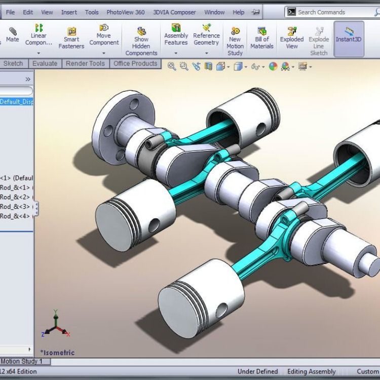 The patient chose the second option.
Treatment plan, methods, process and outcome
Authors whose smile design preferences are as minimally invasive as possible follow a smile design path known as a guided smile concept (GSC). Traditional digital smile design (DSD) invariably involves a single step in the planning process. However, just as guided implantology involves prosthetic planning of implant placement surgery, i.e. planning the final position prior to placement, GSC aims to make the entire smile design process manageable with a 3D end result planned before tooth preparation. The disadvantage of traditional smile modeling is the risk of losing information and, as a result, the impossibility of achieving the planned result with two-dimensional (2D) or even three-dimensional planning. With GSC, the patient's new smile is planned using tooth libraries. Thanks to the use of CAD / CAM technologies in treatment planning, it is possible to maintain the coordinated shape of the teeth and their position as accurately as possible until the stage of final restorations.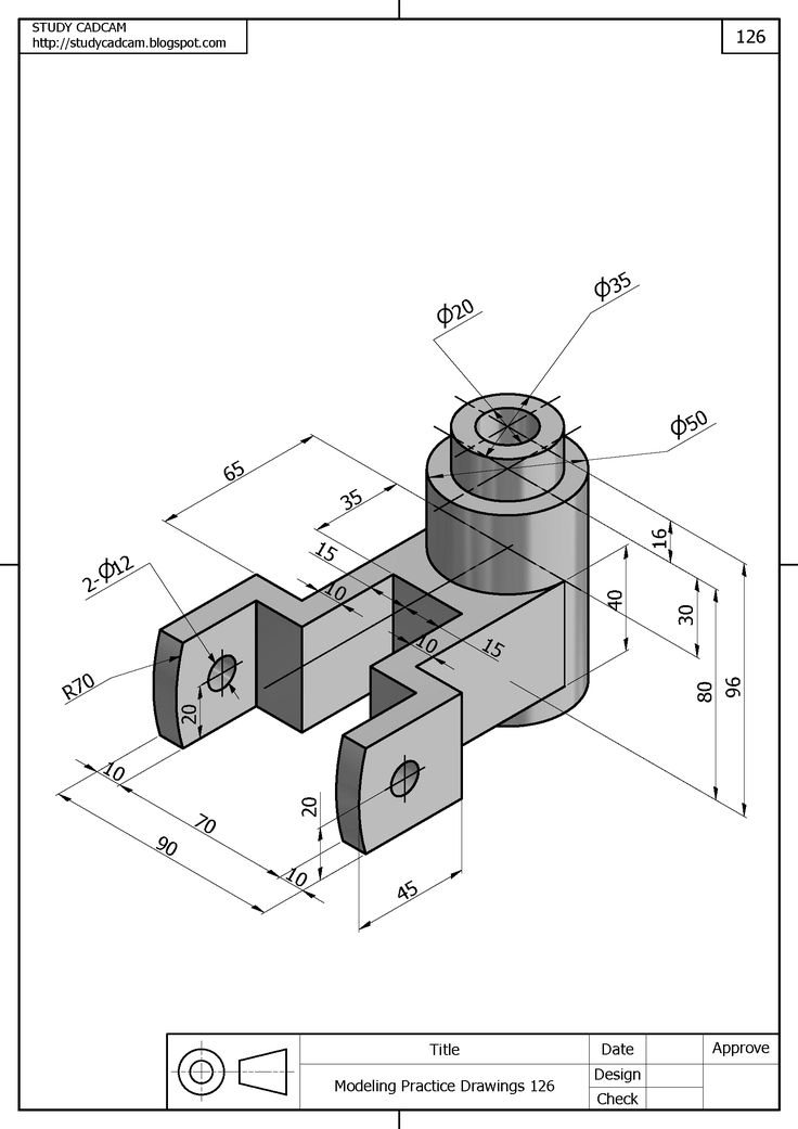
Clinicians should always respect the wishes of the patient, while being mindful of the physical limitations of the restorative material and the clinical situation. For example, a large amount of dental hard tissue may need to be reduced if a bulky anterior tooth is not appropriate for the patient.
Previously, DSD or other 2D smile designs did not require a third party to create a mockup. Digital smile design can be done quickly and quite easily with the right image layering software (Keynote, Powerpoint). These two-dimensional mock-ups, however, are only a guide to help the patient see the potential end result and allow the clinician and technician to visualize important landmarks such as the midline of the face and the interpupillary line as a guide to the tilt of the occlusal plane (Figure 3 to Figure 5). Such mock-ups do not provide the clinician with a detailed view of the three-dimensional morphology of the teeth, which is critical for designing a minimally invasive restoration.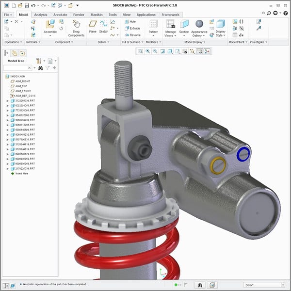 Today in software (DSDApp®, DSD-DigitalSmileDesign, digitalsmiledesign.com; IvosmileApp, IvoclarDigital, ivoclardigital.com) it is possible to visualize a future smile or create a mockup and integrate them into the workflow.
Figure 3. Smile design planning: facial landmarks
Figure 4. Smile design planning: tooth contours
Figure 5. Smile design planning: 2D comparison
3D model of the patient's dentition in Meshmixer or other programs (TRIOS Design Studio, 3Shape, 3shape.com; inLab, Dentsply Sirona, dentsplysirona.com; exocadChairsideCAD, exocad, exocad.com). This manipulation can be performed in several ways. One simple method involves using free software such as Meshmixer and Overlay2 (ColinThomasPhotographyLtd, colinthomas.com). By overlaying a 2D photograph as a "ghost" image, such as a translucent mockup created with a smile design program (SmileDesignerPro, smiledesignerpro.com), the occlusal plane of the 2D image is aligned with the "x" axis in 3D before the 3D patient models are moved and aligned to the correct position with respect to the 2D photo.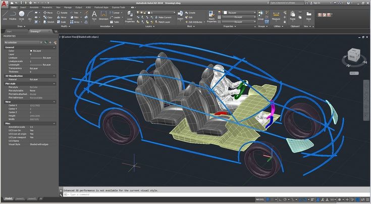 Then this photo can be replaced with a mock-up, and then the 3D teeth from the libraries can be moved to the desired position, and the necessary adjustments can be made.
An alternative and simpler method is available to exoCAD® (exocad) users. The software offers the possibility of simultaneously manipulating a 2D mockup and a 3D mockup with an immediate display of the result.
The 3D mockup is based on a 2D image with the same tooth library, which increases the predictability of the final result.
This approach has the advantage of minimal preparation. As Dr. Pascal Magne said: "It should not be about aesthetics, but about dentistry that saves teeth." The preparation of the tooth must be combined with the aesthetic result. CAD/CAM digital dentistry gives clinicians the ability to see what the end result might be before tooth preparation or any other invasive procedure. Unlike a traditional wax-up, the digital model can be reduced to a given thickness to visualize the amount of preparation of the hard tissues of the tooth.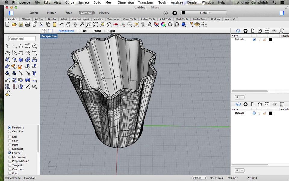 Thus, there is a difference between minimal preparation and no preparation at all, i.e. “minimal preparation” does not mean “no preparation at all”.
Perhaps the biggest benefit of 3D printing is the ability to demonstrate a minimally invasive mockup that both clinician and patient can see, an almost exact replica of what the final esthetic result will look like before any teeth are prepared. Moreover, if necessary, you can make adjustments.
In this case, the dentists used a 2D mockup from smile design software (SmileDesignerPro) and 3D modeled it using Overlay2 in Meshmixer. As discussed above, the 2D image makes it possible to correctly orient the 3D models relative to the occlusal plane in the "XYZ axes". Using Meshmixer, the teeth from the library were placed on top of the scanned STL file (Figure 6 and Figure 7). The palatal surfaces of the added teeth were actually removed to visualize the palatal surfaces of the natural teeth.
Figure 6. 3D Meshmixer mockup; layout overlay on a calibrated occlusal level and a 2D layout.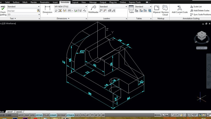
Figure 7. 3D Meshmixer mockup; Using the Meshmixer, the teeth from the library were placed over the natural dentition
Then, using a 3D printer (AsigaMaxUV, Asiga, asiga.com), the model was printed with DentaModel resin (Asiga) with a height of each layer of 50 µm. A polyvinylsiloxane (PVS) print was taken from a 3D printed mockup. The resulting impression was used several times to evaluate the appearance of the future smile, to select the correct marking bur, to determine the final location of the restoration, and the shape from which the final design will be copied after all the adjustments made (Figure 8).
Figure 8. 3D printed mockup and its polyvinylsiloxane impression
The authors chose to make a PVA impression rather than using a 3D printed flexible matrix because no suitable flexible biocompatible materials were available at the time of this procedure. for use in practice. However, some materials are currently available, such as "Indirectbondingtray" pliable resins from various manufacturers, or pliable clear resins such as KeySplintSoft® (KeystoneIndustries, keyprint.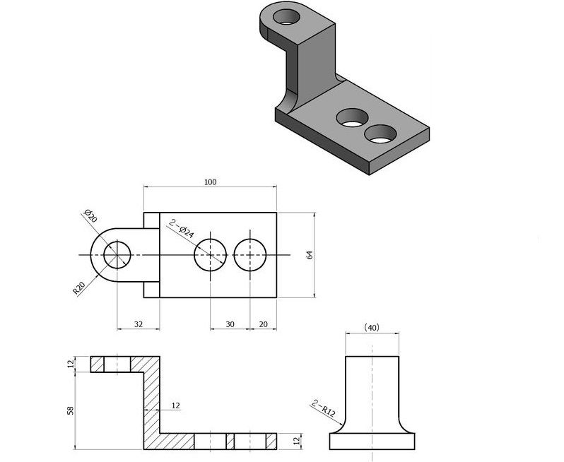 keystoneindustries.com). The option with direct matrix printing can be viewed from two sides. This process saves time because the matrix will be printed instead of the model, so it does not need to be created with PVS. In addition, the matrix will be transparent, which will make it possible to use more durable materials. For example, this method can then be used to fabricate permanent composite restorations that will be cured through a 3D printed matrix.
Due to the advent of the 3D printed matrix, this step can be adapted for gingivectomy, fixing orthodontic treatment or night guards and further use after the fabrication of the final restorations, as they will be copies of the 3D STL mockup.
During the preparation phase, final restorations need to be planned. In this case, CEREC 5.1 software (DentsplySirona) was used for modeling based on intraoral scanning (Primescan, DentsplySirona) of prepared teeth, antagonist teeth and registration of occlusion, as well as a hybrid scan of the oral cavity and a model mockup printed on a 3D printer.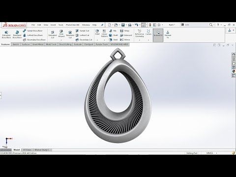 Compared to manual registration, hybrid scanning allows the software to easily align models, providing more landmarks to choose from (Figure 9). The scan results were then used to copy the shape of the adjusted layout directly into the CAD software (Figure 10 and Figure 11).
Figure 9. An intraoral 3D scan was performed along with a hybrid scan of the mockup to be used in the CAD process
Figure 10. The mockup outlines used for copying into the CAD process
9109 Full Figure design
Material selection
Minimally invasive dentistry requires a slight reduction in tooth structure. It is important to be mindful of the patient's wishes regarding the treatment plan to which they have agreed. During the design phase, the minimum thickness of the materials used in CAM technology must be taken into account in order for the materials to be successfully milled and remain strong enough to withstand occlusal loading. For example, IPS e. max® CAD (IvoclarVivadent, ivoclarvivadent.com) offers the possibility to mill material from 200 µm to 300 µm depending on the milling machine and milling strategy (Figure 12). In addition, milling machines have a minimum material thickness (depending on the type of material) that can be milled without risk of breakage. This is due to the physical limitations of the material and depends on the type of cutter. To date, the choice of material is quite extensive. The authors prefer lithium disilicate, which is a proven material, easy to process and highly aesthetic. Figures 13 to 17 show the final results of this clinical case.
Figure 12. Computer automated production
Figure 13. Manded, manually processed, painted and glazed crowns and veneis from lithium diuliquate
Figure 14. The final type
9000Figure 15. The final intra -rode view with Contrast
Figure 16 Close-up final left view
Figure 17 Close-up final right view
Conclusion
Making crowns and veneers for front teeth is a responsible and difficult job. Aesthetic expectations of the patient are usually high, and the final result largely depends on the skills of the dental technician. With the advent of digital dentistry, creating complex shapes and improving occlusion has become easier as the software component of the design process assists the dentist in this. Thus, in-house digital restoration design can now provide high quality, high strength and superior aesthetics. Not surprisingly, all-ceramic lithium disilicate anterior crowns are becoming increasingly popular.
In the case presented, the authors used the concept of a predictable digital smile design following aesthetic principles to select the patient's smile format and then created a mockup based on this digital smile design. In addition to designing veneers with the appropriate surface morphology, the use of stains, glazes, the correct technique and tools used in 3D printing and CAD/CAM dentistry give clinicians the ability to quickly achieve aesthetic results and improve patient satisfaction.