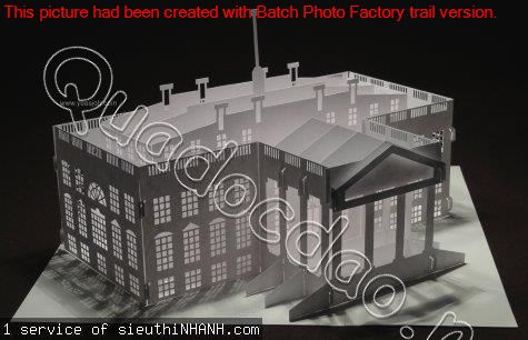
Ho scale 3d printed buildings
Free STL file HO Scale School Building・3D printable model to download・Cults
HO Scale Lasalle House
Free
HO Scale Concrete Factory
Free
HO Scale 68' Yard Light Tower
Free
HO Scale Bungalow
Free
HO Scale Small Barn and Accessories
Free
HO Scale Water Tower
Free
HO Scale Cottage
Free
HO Scale126 ft Steel Arched Truss Bridge
Free
Best 3D printer files of the Architecture category
Our Dream House in Hong Kong.. a place that every hongkonger spend a lifetime to reach
Free
pantheon
Free
Haverthwaite Station, Cumbria, N gauge
€6. 50
H0/other scales bridge tower building model
€1.50
Krusty Krab
€6.12
1/64 Generic Petrol Station
€0.50
Popocatepetl
Free
Gifu Castle
Free
Best sellers of the category Architecture
Colosseum in Rome
€1.99
Leaning Tower of Pisa
€2.50
1-100th scale furniture Architecture
€0.74
Birdhouse -3 pieces
€3.80
Elven High-Castle
€3.98
Medieval door - light
€9.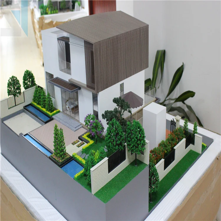 80
80
Machu Picchu Model
€4.80
Toretto house v2
€4.97
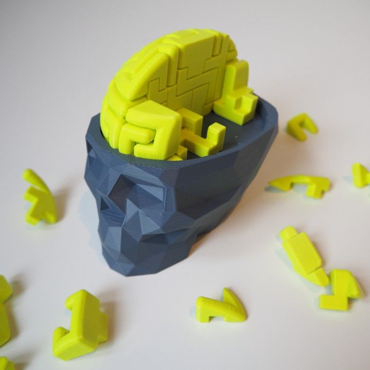
SKULL OBELISK
€2.38
TMNT Sewer Lair Teenage Mutant Ninja Turtles
€11.87
battle sanctum
€8.75
The Space Launch System (SLS): NASA’s Artemis I Moon Rocket with platform. File STL-OBJ for 3D Printer
€2.90
Airbus A330-200 1:500
€0.50
Eiffel Tower - Paris City
€0.99
Ancient Raven Castle
€4.98
Cinderella Castle
€5
Would you like to support Cults?
You like Cults and you want to help us continue the adventure independently? Please note that we are a small team of 3 people, therefore it is very simple to support us to maintain the activity and create future developments.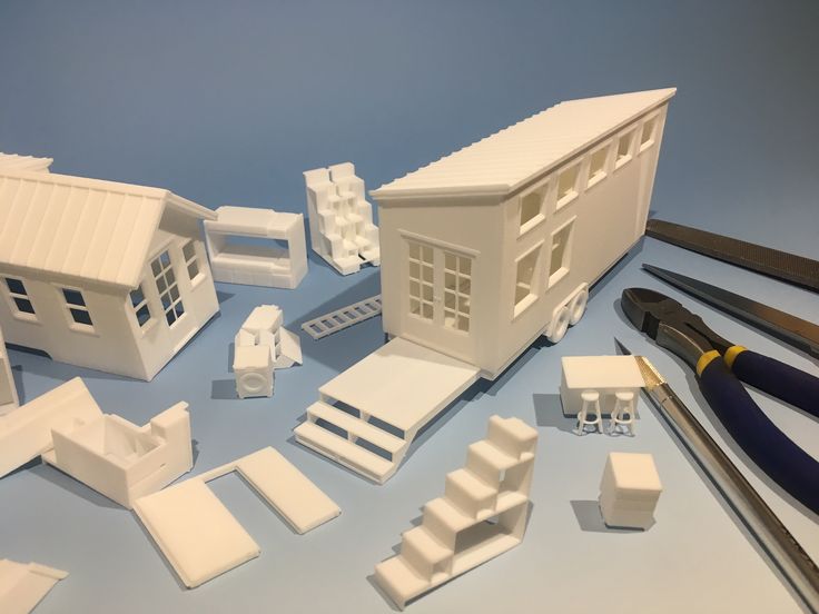 Here are 4 solutions accessible to all:
ADVERTISING: Disable your AdBlock banner blocker and click on our banner ads.
AFFILIATION: Make your purchases online by clicking on our affiliate links here Amazon.
DONATE: If you want, you can make a donation via PayPal.
WORD OF MOUTH: Invite your friends to come, discover the platform and the magnificent 3D files shared by the community!
Model Railway 3D printed scenic details - HO scale – ABR Model Works
-
205-litre/44-gallon metal drums - drum, open drum with lid 40 pack - HO Scale
205-litre/44-gallon metal drums - drum, open drum with lid 40 pack - HO Scale
SKU: 3DPK.002
- Regular price
- $14.49
- Sale price
- $14.49
- Regular price
-
- Unit price
- /per
Sale Sold out
-
205-litre/44-gallon metal drums - HO Scale
205-litre/44-gallon metal drums - HO Scale
SKU: 3DPK.
 035.20
- Regular price
- from $8.49
- Sale price
- from $8.49
- Regular price
-
- Unit price
- /per
Sale Sold out
-
Air conditioner duct 1 section 12L 12w 8h – 10 pack – HO Scale
Air conditioner duct 1 section 12L 12w 8h – 10 pack – HO Scale
SKU: 3DPK.017
- Regular price
- $7.49
- Sale price
- $7.49
- Regular price
-
- Unit price
- /per
Sale Sold out
-
Air conditioner duct 1 section 12L 8w 6h – 16 pack – HO Scale
Air conditioner duct 1 section 12L 8w 6h – 16 pack – HO Scale
SKU: 3DPK.
 025
025- Regular price
- $7.49
- Sale price
- $7.49
- Regular price
-
- Unit price
- /per
Sale Sold out
-
Air conditioner duct 12w legs – 60 pack – HO Scale
Air conditioner duct 12w legs – 60 pack – HO Scale
SKU: 3DPK.031
- Regular price
- $8.49
- Sale price
- $8.49
- Regular price
-
- Unit price
- /per
Sale Sold out
-
Air conditioner duct 2 section 24L 12w 8h – 6 pack – HO Scale
Air conditioner duct 2 section 24L 12w 8h – 6 pack – HO Scale
SKU: 3DPK.
 018
018- Regular price
- $7.49
- Sale price
- $7.49
- Regular price
-
- Unit price
- /per
Sale Sold out
-
Air conditioner duct 2 section 24L 8w 6h – 11 pack – HO Scale
Air conditioner duct 2 section 24L 8w 6h – 11 pack – HO Scale
SKU: 3DPK.026
- Regular price
- $7.49
- Sale price
- $7.49
- Regular price
-
- Unit price
- /per
Sale Sold out
-
Air conditioner duct 3 section 36L 12w 8h – 6 pack – HO Scale
Air conditioner duct 3 section 36L 12w 8h – 6 pack – HO Scale
SKU: 3DPK.
 019
019- Regular price
- $10.49
- Sale price
- $10.49
- Regular price
-
- Unit price
- /per
Sale Sold out
-
Air conditioner duct 3 section 36L 8w 6h – 7 pack – HO Scale
Air conditioner duct 3 section 36L 8w 6h – 7 pack – HO Scale
SKU: 3DPK.027
- Regular price
- $7.49
- Sale price
- $7.49
- Regular price
-
- Unit price
- /per
Sale Sold out
-
Air conditioner duct 4 section 48L 12w 8h – 5 pack – HO Scale
Air conditioner duct 4 section 48L 12w 8h – 5 pack – HO Scale
SKU: 3DPK.
 020
020- Regular price
- $10.49
- Sale price
- $10.49
- Regular price
-
- Unit price
- /per
Sale Sold out
-
Air conditioner duct 4 section 48L 8w 6h – 5 pack – HO Scale
Air conditioner duct 4 section 48L 8w 6h – 5 pack – HO Scale
SKU: 3DPK.028
- Regular price
- $7.49
- Sale price
- $7.49
- Regular price
-
- Unit price
- /per
Sale Sold out
-
Air conditioner duct 5 section 60L 12w 8h – 4 pack – HO Scale
Air conditioner duct 5 section 60L 12w 8h – 4 pack – HO Scale
SKU: 3DPK.
 021
021- Regular price
- $10.49
- Sale price
- $10.49
- Regular price
-
- Unit price
- /per
Sale Sold out
Architectural 3D Printing Modeling Strategy and Software Usage Guide
At a Glance
3D printing provides tremendous benefits to the conventional architectural workflow. You can print complex designs without the need for skilled craftsmen, and quickly modify these designs without too much difficulty. Stereolithographic (SLA) 3D printing delivers incredibly high surface quality and detail, making it suitable for architectural applications. This paper explores modeling strategies and software workflows that enable architects and designers to easily integrate 3D printing into existing design methodology, create best practices based on internal testing by Formlabs and architecture firms, successfully using Form 2 to create 9 models0005
WHAT YOU WILL LEARN:
Strategies for designing 3D printed architectural models
Tips for improving your workflow Pre-print processing software
- Building information model (Revit, ArchiCAD)
- Surface modeling (Rhino, SketchUp)
Good post-processing techniques
- Compound
- Finishing
Introduction
The 3D printing market today offers affordable options in both price and scale. While professional-grade technology used to be costly, desktop stereolithography 3D printers allow architects, designers, and model makers to offer high-quality, in-house fabricated parts.
Most models cost less than $10 per part.
3D printing opens up opportunities to create complex designs with less effort and fewer materials, but the successful transition from a CAD model to a printable file is based on a basic understanding of design for 3D printing. This document will help you understand how standard modeling constraints relate to preparing a file for 3D printing, as well as approaches and decision making for intelligent modeling - from scale selection to design and assembly for post-processing.
To integrate these strategies into existing workflows, this booklet explores ways to approach modeling strategies tactically by examining three of the most common software ecosystems: allows you to include small details even on the smallest models. This example of a small city model has a scale of 1/32″ = 1’ and is completely printed on a Form 2 3D printer. Many small details and parts of this design will take significantly longer if cut and assembled by hand. Model from LaneyLA Inc.
This auditorium section was 3D printed as one piece on a black resin Form 2. Model from DLR Group.
Modeling strategy
Architectural models are usually assembled using various materials and components. 3D printers help combine these components into as few separate parts as possible, but assembly manipulation is still necessary for two reasons:
- Build Volume Limitations : High build volume printers are either expensive or compromise on surface quality. Form 2 build volume is 57 x 57 x 69 inches (145 x 145 x 175 mm)
- Need to show interior details or materiality : Some models require components to be separated to show more design information.
DESIGN FOR ASSEMBLY
All 3D models require preparation before they can be sent to the 3D printer. In the case of architectural models for the Form 2, this often involves splitting the model into smaller parts to fit the scope of the Form 2 build. The parts can then be easily joined together by chemical adhesive or mechanical assembly; high precision printing ensures that the parts fit together.
Dimensioning for parts to be separated must take into account the final orientation of the model. Most architectural prints need to be oriented at a 45 degree angle due to floor slabs being considered large horizontal projections. Dividing the model into long, thin parts helps maximize the diagonal length of the build volume while achieving perfect orientation
Strategy overview
There are several strategies for assembling 3D printed models. Your strategy will depend on what you hope to represent with the design, as well as the scale and geometry of the model. Consider the following parameters:
- Need to show internal or external parts
- Easy Split (You want to split the model by the least complex part of the model)
It is necessary to show a certain part of the program: typology, structure, floor layout
| Seam separation | Separation by component |
| Section model | Separation by program |
| Straight cut | Separation by structure |
| Aligners |
Splitting at the seam
STRAIGHT CUT
The easiest way to split the model is with a straight cut. This is a simple command to execute in most CAD software. The bridge model is divided lengthwise using straight cuts into four parts, one of which is shown above. Each support post is inserted into
mating hole that does not require glue. Regardless of which method you choose, if you have a large number of parts (more than 10), it can be helpful to add a unique identifier for each part to help solve the puzzle during assembly.
Pros:
- Least heavy use of CAD
- Greater tolerance for prints that warp or have a higher degree of dimensional change
Cons:
- Assembly requires manually leveling each piece and fixing it in place until the adhesive is fully bonded
Try to print all components in the same orientation so that the layer lines and subsequent dimensional inaccuracies follow the same pattern.
ALIGNMENT TOOLS
Another approach is to add features to the design that will allow the prints to align. When adding mate fixtures, try to subdivide the model in areas with the least complex geometry. Use the CAD tool of your choice to split your model and add basic alignment fixtures such as slots, pins, grooves, recesses and flanges, or more complex fixtures such as dovetails and cuts that follow existing model curves. In addition, it is important to create a design with ~0.25 mm tolerance between mating parts to prevent additional sanding at the post-printing stage.
Pros:
- Easy alignment Parts that are not accurate
- Easy to assemble (mating parts help create a large surface area for adhesion)
- High precision SLA allows tight fit with high tolerance and can be used without adhesive
Cons:
- Parts that are not true to size will not fit well. High fine details are often less accurate.
SECTION MODEL
The separation of the model with a seam has the additional task of showing the section model for structures with irresistible interior details. Initially, the model can be presented as a whole to the client, and then disassembled to reveal interior details as desired. These LaneyLA examples show how the same model conveys different types of information based on open and closed configurations
This model from LaneyLA was printed on a White Resin Form 2.
Using devices for combining: Methods component
SOFTWARE DIVISION
By splitting a building with software, you can represent the building as a set of parts, providing a clear understanding of all design components without a plan and section drawings. You can print each floor slab separately and then assemble using mates, or just print one component of the entire building separately from the rest. A good example is the model from Stanley Sitetowitz | Natoma Architects Inc (SSNAI), who used the Form 2 to model the residential complex.
Model by Stanley Sitetowitz | Natoma Architects Inc.
Since each body block followed the same pattern, it makes sense to simply print one detachable block that will allow the customer to understand the typology of the typical device. to print as a single block or separate along the seam.
This method usually works for models that are not linear, such as typical building blocks, but complex structures, such as detailed building sections, bridges, pavilions, or airports.
First, break these models down into components that can be 3D printed with minimal supports. This saves post-processing time (removing supports for delicate models can be tedious) and reduces material costs and print times.
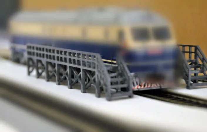
This bridge example demonstrates multiple partitioning methods. First, the model is divided into several parts (Figure a). Although they fit the
Form 2 build platform, they require painstaking removal of supports around more delicate areas such as cables and railings.
To solve this problem, each part is broken down into three sub-components: base plate and railing, vertical tensile cables and solar panels on top (figure b).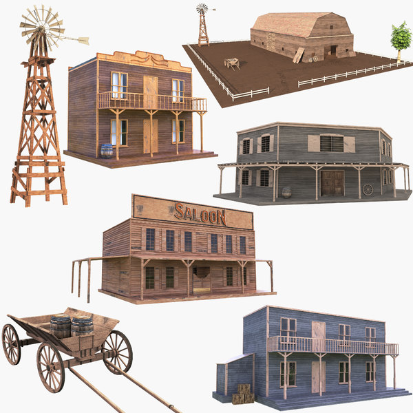 They can be printed with significantly fewer supports, making it easier to finish,
Once completed, the components simply need to be assembled using the alignment functions that were included in the design phase. Smaller parts are also easier to place on a single build platform, with the entire bridge being printed from five 100ml parts.
Model from T.Y. Lin Architects
This site model was created using laser-cut fiberboard. The primary building was 3D printed from clear and white resin. Model by Schwarz Silver Architects
Materials
Materials play an important role in conveying the basic design concept. It is not always necessary to model the exact color and texture of a material, but it can help separate different materials. Dividing a model into its components allows for the display of materiality, as parts can be printed in different materials or individually dyed in different colors.
The transparent façade is illuminated from within, simulating the visual conditions of this site at night.
Formlabs Matte Resins
Black, White and Gray out of the printer have a smooth, opaque finish and provide an excellent neutral palette for architectural models. Gray and white resins are also easy to process and can be finished with just a few coats of paint, as discussed further in the finishing section of this document.
Formlabs Clear Resin is excellent for printing features that mimic translucent materials. If your model requires more transparency, you can simply dip the printed part in clear resin and let it dry evenly, as described in this article on making clear resin parts. You can also spray any clear coats on the model to increase the transparency and glossiness of the surface.
3D PRINTING AND TRADITIONAL MATERIALS
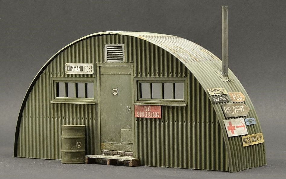
This model uses the Form 2 to print very fine details such as the cornice, clock and railing. Model by Miles Burke Architectural Models Inc.
Instead of 3D printing an entire building, sometimes it's better to print just the complex components. Complex facades, slings and cornice details are excellent candidates for SLA 3D printing. Flat walls, floor slabs and topography can be laser cut or even hand-drawn
This complex façade is parametrically designed from solar trajectory analysis and would be incredibly difficult to fabricate in any other way at this scale.
Software workflow
Good printing comes from a well-designed 3D model. This section will cover modeling best practices and workflows for printing in some of the most common CAD environments:
Revit, SketchUp and Rhino
CAD software is typically the bottleneck in the transition from drawing to 3D printed model
General workflows
IMZ workflow
IMZ workflow
Model → Revit3Diagnostics → Sketch3Diagnostics 900 PreForm
Although BIM (Building Information Model) software is popular with architecture firms, it is not always used for direct 3D printing models.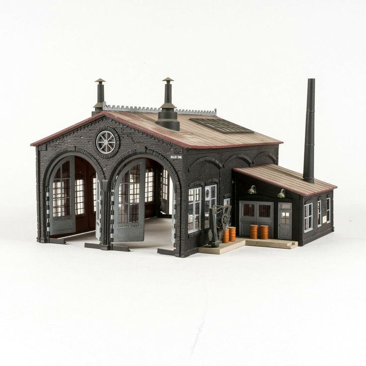 There are some high level steps that you can take
take to create a 3D printed model from these programs. This workflow is widely applied to Autodesk Revit or Graphisoft ArchiCAD software, both of which are IMZ parametric modeling programs.
PREPARE THE FILE
STEP 1: Prepare a stand-alone file
STEP 2: Component Management: remove ducts, double glazing, HVAC units and internal parts that will not be visible in model
STEP 3: Select all components to be sealed (eg doors, windows, walls, slabs). The parametric nature of the model allows you to simultaneously compact the dimensions of several objects.
EXPORT FILE
Select the scale at which you want to export the file. Select export options depending on the needs of your model:
EXPORT AS STL
Exporting the file as a mesh is very difficult to manipulate, so this is only useful if you don't want to edit any geometry after this step.![]() You can then use your software to correct the mesh of your choice, as well as subdivide the mesh along the main Cartesian planes.
You can then use your software to correct the mesh of your choice, as well as subdivide the mesh along the main Cartesian planes.
EXPORT AS 3D DWG
Export as surfaces allows you to easily manage and edit geometry in Rhino or SketchUp. This step is recommended for those who want to split the model programmatically or by component, or split by a seam that is not on the normal Cartesian plane. You can then export the STL file from Rhino or from SketchUp using the plug-in
EXPORT USING ARCHICAD
Perform a geometry transformation to Morphs and a "consistency check" before exporting the model as STL. When printing in parts, use tool
"Divide" to cut the model for multiple print platforms, if needed. This operation basically creates printable files, but a quick check in mesh repair/analysis software never hurts.
USING STL REVIT EXPORTER
This method automatically removes smaller details such as doorknobs and railings.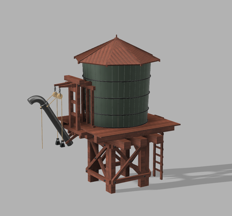 However, it is not reliable and still often requires some post-processing in other CAD environments before being sent to print.
Surface Modeling Workflow
AutoCAD → Rhino/SketchUp → Model Diagnostics → PreForm
This workflow is often an easier approach and starts with 2D drawings solely for the purpose of 3D printing
FILE PREPARATION
STEP 1: Hide unwanted layersSTEP 2: Identify and remove unnecessary elements such as furniture, trees, etc.
EXPORT FILE
STEP 1: Export the simplified drawing from Rhino as DWG
STEP 2: Import into Rhino
STEP 4: Start extruding and trimming until you get the outer shell.
STEP 5: Export as STL STEP 6: Mesh Analysis/Correction STEP 7: Import to PreForm
Note: If the model will be printed in several parts, split it before exporting as STL
THICKNESS WITH RHINO
Instead of parametrically controlling the thickness of components directly in the BIM file, you can also use the BoxEdit component in Rhino.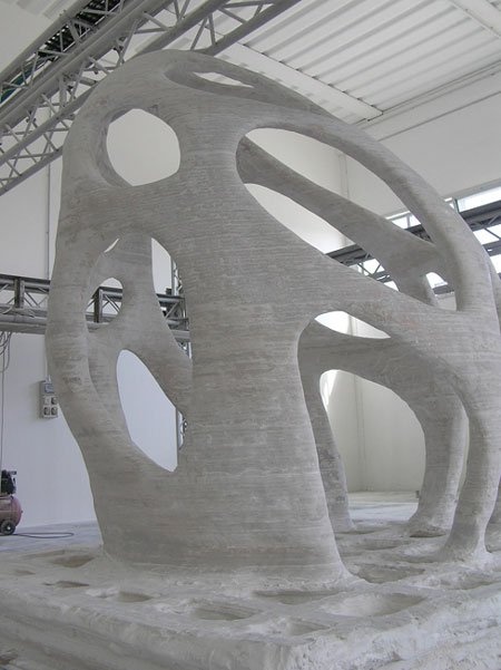
This allows you to simultaneously scale a number of elements with respect to their center lines. BoxEdit is ideal for models that need to be scaled parallel to three Cartesian axes. Non-uniform scaling is a little trickier.
For non-rectilinear geometries, we suggest converting the part to a mesh and then using the Weaverbird thicken command, which simply offsets any non-standard mesh geometry outward by a given distance. Alternatively, it is possible to "split" complex parts into surfaces and then offset them instead of importing volumes from Revit.
SELECTING SMALL GEOMETRIES WITH RHINO
Another valuable Rhino feature is the SelSmall command, which allows you to select all elements in the Stage that are smaller than a custom bounding box. You can then select those objects and use
BoxEdit for individual scaling or just remove them. This is useful when you are dealing with a file that does not have a well organized layer system.
Although performing a logical connection on all geometries is ideal, often the problem can be solved with simple overlapping geometries. PreForm will interpret them as one closed geometry in most cases, but be sure to check printability with the "slicer" tool in the right pane in PreForm
. CONTINUOUS / LOGICAL JOINT GEOMETRY
Note : PreForm is Formlabs free software that prepares your 3D model for printing in Form 2. Once the part is set up, you can save it as a FORM file for future use in preform.
COMPUTATION WORKFLOW
Although it is a less common workflow, computational design is slowly being introduced into mainstream architectural workflows. Software such as Grasshopper and Dynamo are used to create parametrically generated geometries that are often so complex that they can only be created with 3D printing.
Since geometries are already easy to manipulate, it's usually best to create a separate component that allows you to easily control the basic dimensions of all thin objects.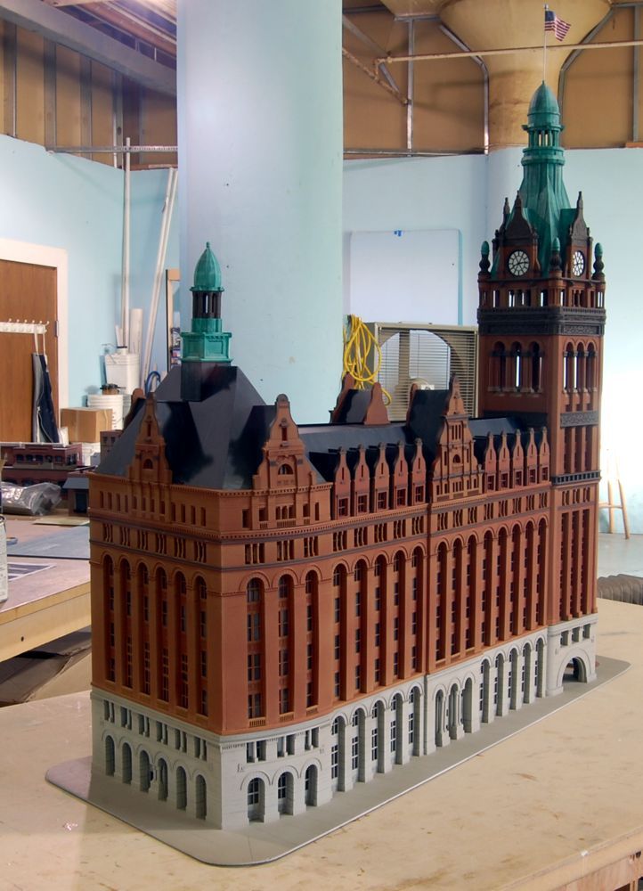 In this case, it's a simple matter of trial and error; running the exported geometries with a print test (PreForm,
MeshMixer) and resizing until you arrive at a printable file.
Model Diagnosis
All workflows described below share a potential "generic diagnosis". This is an optional (but often necessary) step to ensure that the model is fully printable. Free programs such as Autodesk's MeshMixer and Netfabb are tools that allow you to repair, smooth, cavity, and split 3D print files.
MESH FIX
Formlabs PreForm software uses Netfabb's built-in mesh fix, so NetFabb and MeshMixer must be used for custom fixes or to preview problem spots in print. Materialize Magics is a great proprietary tool that covers the entire preprint workflow for a wide variety of printer types. The mesh patching software part is most important to the Form 2 print workflow and can save you a decent amount of preparation time. Netfabb has a beautiful built-in model cutter that allows you to effectively split and restore large files along any Cartesian plane.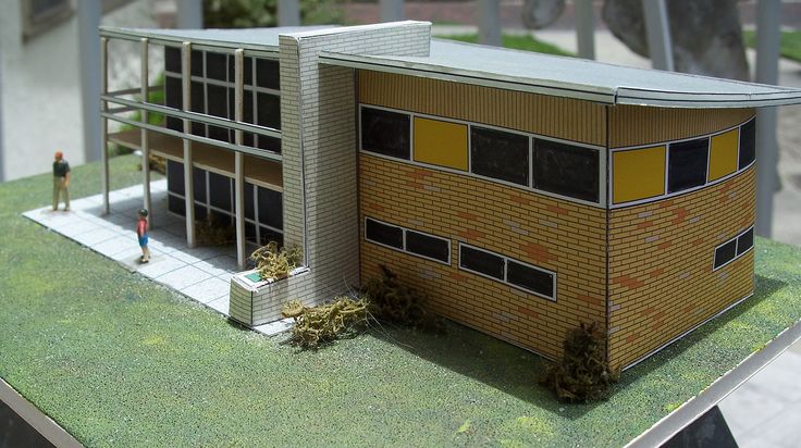
SPLITTING THE MODEL
It is also possible to split the model in NetFabb, which splits and fixes the split parts into printable volumes. In Rhino, you will need to close open volumes. Be sure to leave a tolerance of ~0.25mm between adjacent pieces, this will allow them to be inserted without friction.
For more information on tolerances, see our white paper.
PREFORM SLICER
Architectural models are highly detailed and it is often difficult to isolate each print issue. A combination of the above practices and mesh repair software is usually used for almost all problems, but it's always wise to use the PreForm Slicer tool to make sure there are no thin unsupported areas and enclosed volumes (such as rooms with no doors, elevator shafts, and parking spaces) .
“Building and architecture structures are not meant to be 3D printed, they are meant to be built. This creates problems of scale and complex geometry.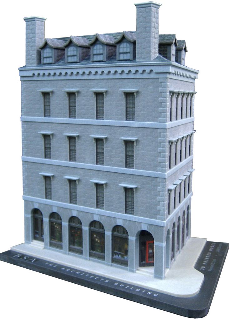 By combining Netfabb's powerful mesh repair tools with the precision of the Form 2, you can prototype and visualize designs faster and in more detail, benefiting more for your business and speeding up your project's design review process.”
Matt Lemay. Lead Enterprise Solutions Provider, Autodesk Customer Service
Post-Processing
Joining
The modeling strategy section of this booklet covers some ways of splitting and aligning parts together, but glue is always needed to securely join. Architectural parts are bonded in two main ways:
CYANOACRYLATE
Cyanoacrylate (CA or Super Glue) creates a fast, strong enough bond, ideal for small to medium sized parts. CA does not bond dirty surfaces well, so be sure to thoroughly clean the part before applying adhesive to the surface of the model.
POLYMER
For smaller prints, you can use liquid resin as a binder. Dispense a small amount of resin into the tray from a bottle or cartridge, use a dropper or syringe to lift it up, and place it on the surface of the part to be bonded.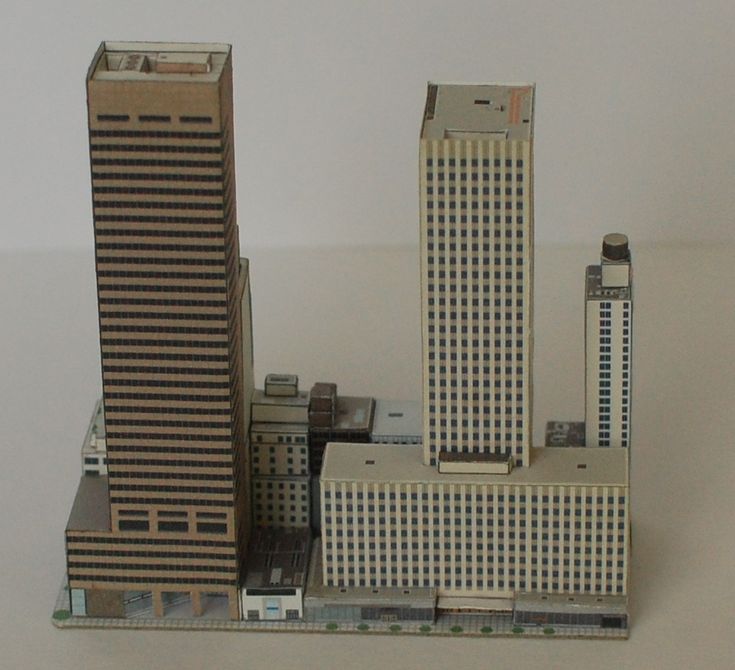
Join parts and wipe off any excess resin that may be spilling around the edges. To cure the resin and bond the parts, use a 5 mW laser pen at 405 nm and point it at the bonding area around the parts.
This method creates a chemical bond, just as if the part had been printed on your SLA 3D printer, but only applies to small bonding surfaces because a low power laser pen cannot penetrate the model deep enough to create a strong bond .
FINISHING
Parts printed on Form 2, especially matte standard resins, have a smooth surface as soon as they exit the printer. However, visible areas with supports almost always require sanding. In addition, you can prime and paint parts in any desired color.
GRINDING
Sanding will help you remove the support marks and any remaining inaccuracies from your model. Start by carefully dry sanding the surface of the part using ~150 grit sandpaper to remove large support marks and smooth out the edges of the joint. Once the surface of the part is smooth, wet sand with 320mm sandpaper to remove any remaining layer lines. Move the sandpaper randomly to avoid grain formation.
In most cases these two steps will create a fairly even finish, but you can continue to increase the grit size of the sanding paper by a factor of 2 and wet sand the entire piece until the surface is smooth enough.
Once you have finished sanding your model, wash the model in soapy water to remove any dust or debris and dry thoroughly before proceeding to the last step.
The architectural models are very detailed and it is quite difficult to access certain areas with only sandpaper. You can use different sizes of nail files to get to problem areas of the model.
PRIMER AND PAINTING
Priming is required before parts are painted to ensure the paint adheres to the surface. Priming can also make it easier to find areas that require additional finishing. A quick spray of primer over the model makes the support marks very visible, so you can instantly identify areas that need additional sanding.
General plastic primer gray matt shows details very well. Apply it to surfaces in several thin layers for best results. Continue sanding in critical areas, reapply a light coat of primer and repeat this process until the entire part is smooth. Most spray paints work best in warm, slightly damp conditions with no airflow, but always check the specific paint or data sheet for manufacturer's recommendations.
“Models are becoming rarer in a field where photorealistic renderings and virtual reality technology are advancing, but physical models allow architects to test spatial qualities in ways that digital models cannot. If we weren't using a 3D printer, we would be forced to spend more time visualizing designs through renderings and drawings. Being able to get a physical model of a complex design straight from a 3D CAD model gives us several impressive looks in less time.”
Paul Choi
Read an article about the first 3D printed houses?
3D printing has been used in construction for several years now. In this article, you will learn about the first real houses printed on 3D printers.
3D printing of houses is still quite new to the layman. While construction 3D printing technologies have been developed for many years, only a few "real" projects have already seen the light of day. We are still far from technology taking over conventional construction methods. But with each new project, she is getting closer to becoming mainstream.
There are many benefits to 3D printing. For example, the cost of a 3D printed house can be much lower. And it will take much less time to build.
In order to draw a line under what has already been achieved in this area and show some interesting projects, we have devoted an article to the "first" and the best. These projects will always remain milestones in the construction 3D printing industry as they set the stage for future advances in the field.
First 3D printed house in Germany
Germany is a country often associated with cutting-edge engineering, so let's start our list with Germany's first ever 3D printed house.
The house itself is located in Beckum, a city that is partly located in North Rhine-Westphalia, next to Holland and Belgium. This is the first 3D printed house to be fully certified to official building codes. This project will give way to many other 3D printed construction projects in Germany as well as the rest of Europe.
The project is the result of a collaboration between German construction company Peri and Danish construction 3D printing firm COBOD. Peri is a large corporation that operates not only in Germany, but throughout the EU. Its portfolio includes many products, including scaffolding and formwork solutions that every construction site needs.
Peri followed the construction 3D printing segment for years before acquiring a stake in COBOD in 2018. Now they are pushing the technology together and further. The construction of the house in Beckum began two years after the acquisition of the share.
For 3D printing at home, a BOD2 modular 3D printer from COBOD was used.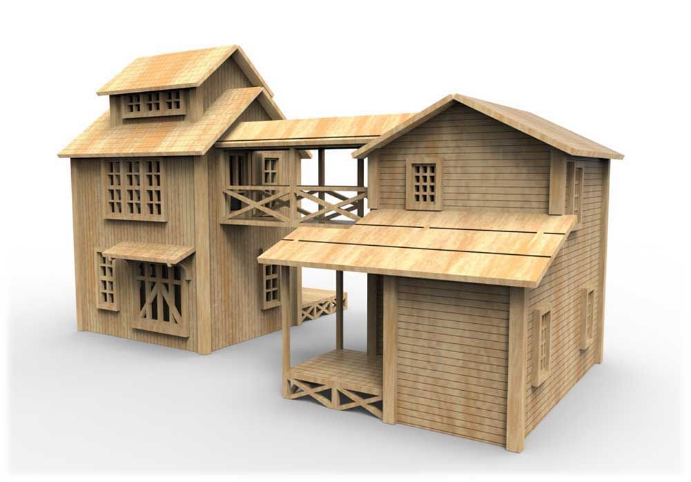 The printing itself took just over 100 hours.
• Built: (started) September 17, 2020
• Commissioned: summer 2021
• Where: Beckum, North Rhine-Westphalia, Germany
• By: Peri, COBOD
First occupied 3D printed home in the US
Several homes have been printed in the US, but this home is the first officially occupied home, according to CNN. Its creators: the construction company Alquist and the humanitarian organization Habitat for Humanity Peninsula.
From a distance, you might think that this is an ordinary house. However, when approaching it, the layered structure of the concrete walls becomes noticeable. After all, 3D printing creates an object in layers.
Surprisingly, the 111.5 square meter concrete structure of the house (was printed in about 12 hours, significantly faster than traditional construction methods would allow.
The house was reportedly purchased by April Springfield, who lives there with her son and dog She bought the house through Habitat for Humanity's housing program, and given that the nonprofit's goal is to help solve the global housing crisis, it makes sense to use 3D printing to create affordable homes that will make many people's dreams of home ownership come true.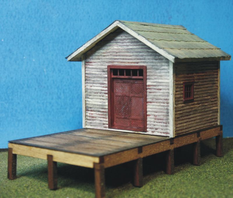 0005
0005
• Built: 2021
• Commissioned: December 22, 2021
• Where: Williamsburg, Virginia, USA
• By: Alquist 3D, Habitat for Humanity Peninsula, Greater Williamsburg
The first five-story 3D printed house
This project, made by the Chinese company WinSun, is a real record holder. It is a 3D printed five-story residential building with a height of 10 meters - the tallest 3D printed building so far.
The house is located in Suzhou Industrial Park in Jiangsu province in eastern China. It stands next to a mansion that was also built by WinSun using a concrete 3D printer.
Looking at the WinSun designs, you can't help but notice that they don't look like they've been 3D printed. Usually 3D printed structures are gray in color, the layer lines are clearly visible. But WinSun adds color and makes walls smoother. Nowhere is it stated how the company achieves the smoothness of the walls, but we assume that the workers smooth them by hand.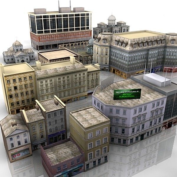 WinSun projects are not like the ones we're used to.
• Built: Winter 2014
• Commissioned: Not specified
• Where: Suzhou, Jiangsu, China
• By: WinSun
First 3D printed biodegradable house
Can you guess that there is rice in the walls of this house?
Most 3D printed buildings are made from concrete mix. But this project is different from the rest. With the aim of creating housing solutions with little to no environmental impact, Italian company WASP 3D printed Gay's house using soil and agricultural waste.
WASP developed the sustainable blend in collaboration with Ricehouse, a company that specializes in using natural and agricultural materials such as clay and rice in construction.
The house is named Gaia in honor of the ancient Greek goddess of the earth. In fact, 25% of the mixture contains local soil, 10% hydraulic lime, 25% rice husks and 40% crushed rice straw (a by-product of rice production at harvest).
An innovative solution not only in terms of material, but also in the design of the walls themselves. The specific corrugated structure was used to provide ventilation on warm days as well as insulation on cold periods, virtually eliminating the need for air conditioning.
Gay's house is small - about 20 square meters. The wall printing took only 10 days, while the estimated materials cost is just under $1,000.
• Built: not specified
• Commissioned: October 7, 2018
• Where: Massa Lombarda, Ravenna, Italy
• By: WASP, Ricehouse
AirBnB's first 3D printed home
The perfect weekend getaway.
There are many different types of accommodations on AirBnB, but what about a 3D printed home?
The so-called Fibonacci house is the first 3D printed house to be offered for booking through AirBnB. Considering that it is located in rural British Columbia, it will be a wonderful place to stay.
Although the Fibonacci house looks small, it has a lot to offer vacationers. About 35 square meters is enough to accommodate up to four people.
The concrete walls of the house were designed and printed by Dutch 3D printing firm Twente. 20 concrete parts were produced offsite in just 11 days. The material was produced by Laticrete. The parts were later transported and assembled at their current location.
• Built: 2020
• Commissioned: Not specified
• Where: Kootenays, British Columbia, Canada
• By: Twente Additive Manufacturing
First 3D printed houseboat
Prvok is not only the first 3D printed house in the Czech Republic, but the world's first floating 3D printed house on a pontoon.
The project was carried out by the start-up company Scoolpt. The concrete structure of the houseboat took only 22 hours to print.
About 43 square meters of living space divided into bathroom, bedroom and living room with kitchen. Weight isn't usually discussed in the context of houses, but given that this one is on water, it's interesting to note that Prvok weighs 43 tons.
The house is equipped with a built-in recirculating shower and tanks for drinking and municipal water and has a service life of at least 100 years.
• Built: June 2020
• Commissioned: August 18, 2020
• Where: Prague, Czech Republic
• By: Scoolpt
Europe's first 3D printed residential house
Not every 3D printed house has visible line layers.
More often than not, 3D printed houses are demos made to show what the technology can do. For most of them there is no information about the actual residents. But in 2017, the couple did move to live in a 3D printed house located in Nantes, France. Thus, the house of "Yanov" became the first of its kind, which was inhabited in Europe.
The house is a project of the University and the Laboratory of Digital Sciences of Nantes. An interesting aspect of the project is the special technique used in its construction by BatiPrint3D. Instead of 3D printing a concrete structure, the robotic arm created wall shells using polyurethane, a material used for insulation. Later, these membranes were filled with concrete.
It took a total of 54 hours to print. It took a little over 4 months to complete the construction. Mainly due to the fact that the rest of the components were created using conventional means. House area - 95 square meters.
• Built: 2017
• Commissioned: March 2018
• Where: Nantes, France
• By: University of Nantes, Nantes Digital Science Lab
India's first 3D printed house
This building was built in a couple of days.
India's first ever 3D printed house was completed back in 2020. The project was carried out by construction startup Tvasta, founded by graduates from the Indian Institute of Technology Madras. In fact, the institute's Chennai campus was chosen as the location of the building.
The significance of this project lies in its possible impact on the solution of the housing crisis worldwide and in India in particular. The ability to build such a house within a few days and at a low cost cannot be underestimated.
House 55.7 sq.m. with a spacious layout, one bedroom, combined kitchen and living room.
The concrete structure of the house was 3D printed off site and the parts were later transported and assembled on campus. The foundation, meanwhile, was built using the conventional method of pouring concrete into the ground.
• Built: 2020
• Commissioned: Not specified
• Where: Chennai, India
• By: Tvasta Construction
Africa's first 3D printed house
Back in 2019, in the Moroccan city of Ben Guerir, Spanish firm Be More 3D created Africa's first 3D printed house. The project originated during the team's participation in the Solar Decathlon in Africa. This is an international competition during which teams design and build solar-powered houses.
Be More 3D printed house 32 sq.m. in about 12 hours, took first place and received the title of the most innovative startup.
Be More 3D didn't stop building in Africa and later created the first 3D printed house in Spain and developed its own concrete 3D printer in partnership with several corporations from the automation and materials industry.
• Built: 2019
• Commissioned: Not specified
• Where: Ben Guerir, Morocco
• By: Be More 3D
First 3D printed home for sale in the US
Last on our list is the first 3D printed home for sale in the US.
This house was printed on the same site by SQ4D, a company specializing in the development of robotic building systems. The building was printed with SQ4D's Arcs concrete extrusion system and has a 50-year warranty on the printed structure.
Living area of 130.7 sq.m. with three bedrooms and two bathrooms. There is also a garage for 2 cars.
The house was listed for sale in January 2021 for $299,999. Considering the size of the house and the fact that it is priced 50% below the cost of comparable newly built houses in the same area, the deal is pretty good.
• Built: 2020
• Commissioned: 2021
• Where: Riverhead, New York, USA
• By whom: SQ4D
Translation source: https://m.