Grbl 3d printer
Bengler: GRBL
Claim to Fame
Tight implementation of an advanced motion planner
License
MIT
Language
C
Documentation
Wiki
Source
Github
Current lead developer
Sonny Jeon
Pronounciation
Gerbil (jûrbl)
Released
2009
4 updates Latest: GRBL with permissive license (MIT) …
Grbl is software for controlling the motion of machines that make things. If the maker movement was an industry, Grbl would be the industry standard.
Most MakerBots and open source 3D printers have Grbl in their hearts. It has been adapted for use in hundreds of projects including laser cutters, automatic hand writers, hole drillers, graffiti painters and oddball drawing machines. Due to its performance, simplicity and frugal hardware requirements Grbl has grown into a little open source phenomenon.
When we ordered our first computer controlled mill in 2007 we were stumped as to how we would control it. Common practice at the time was to rescue an ancient beige box PC with a parallell printer port and use that to pulse the stepper motors. That just felt wrong. We wanted a simple embedded system that would talk USB with our laptops.
Choosing a controller
We decided on the Arduino for several reasons. Most importantly it was, and still is, the most popular embedded system in the DIY community. It is a touchingly simple computer. A beautifully simple processor that was actually designed here in Norway.
Yet it is a terrifyingly puny machine in the face of this task. Its 2kb of memory laughable even by early 80s standards. Here you go, a picture of the Arduino with enough bits of 80s phenomenon Billy Idol to completely fill its working memory:
What Grbl has to do in 2kb:
- Parse G-Code, a cryptic computer language hailing from the 50s used to describe the idealised actions of milling machines.
- Build a model of those actions and translate them into a physically possible sequence of motions for the given machine.
- Execute these motions by sending a unwavering stream of concerted high frequency pulses to the stepper motors that are actually moving the tool.
Making it all fit
Getting the Arduino to do this in a robust and timely manner felt exactly like threading your run of the mill camel through the eye of a needle. The planner was especially interesting to design. It is the part that looks at a section of the intended movements and calculates sensible cornering speeds and smooth accelleration profiles to ensure accurate operation within the realm of the physically possible. It took us almost a year of tinkering and toying around in C and Mathematica to get it right. Our implementation is not theoretically optimal, but it is really good, simple and computationally spartan.
Uptake
Apart from the home milling enthusiasts using Grbl to control their machines, the code has been adopted and adapted by a myriad of projects. .
.
Some projects using Grbl
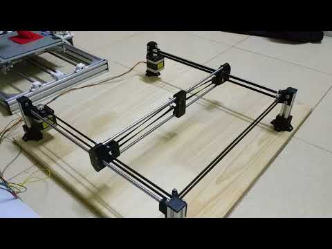
MIT Center for Bits and Atoms designed a beautiful snap fit CNC machine controlled by Grbl.
Nortd Labs runs their open source laser cutters with a Grbl-based firmware
Synthetos designed and sells the grblShield – an Arduino shield with powerful stepper drivers.
Franklin W. Olin College of Engineering built this awesome hand-writer Herald.
Edward Ford designed and sells the powerful and simple CNC mill Shapeoko. It seems to be the most consistent provider of bona fide Grbl users these days.
University of Queensland designed this compact PCB mill for its students to have a cheap and fast method of prototyping printed circuit boards for team projects and other research based projects.
Building from our planner, Emmanuel Gilloz got his 3D printer to move at unprecedented speeds. So much so that his YouTube viewership accused him of speeding the video up.
The 3D-printer firmware Sailfish incorporates our planner and was the official firmware for Makerbots until they lost their way and went closed source. (Our licence precludes integration into closed source projects.)
The very popular and malleable 3D-printer firmware Marlin uses Grbl for motion control.
Also: Zapmaker Grbl Controller, jViewer, GCode sender, R2C2 moving at 650mm/s, Grbl Tidy Case, Smoothie, node-grbl
Other projects
-
Principal Components
Machine learning in search of the uncanny
-
PANDA
Supercolluder for the gig economy
-
OMA Website
Simple surface, intricate clockwork
-
Terrafab
Own a small slice of Norway
-
Underskog
Friendly community for the Norwegian cultural fringe.
-
Chorderoy
Efficient text input for mobile and wearable devices
-
Intersections
Laser sintered topological maps for cars and social scientists
-
Mapfest!
Helping liberate Norwegian geodata
Updates
Grbl best STL files for 3D printing・Cults
DREndLaser
Free
GRBL board holder
Free
80mm Fan standoff
Free
3D Printed DIY CNC - Dremel CNC Remix
Free
bCNC USB Pendant-with button
Free
Folding laser engraver/cutter
Free
The Big Plotter
Free
The selfdrawing painting
Free
Lasercutter
Free
Láser CNC
Free
Engraver Laser Engraver 1500mW 150 x 250 mm
€9.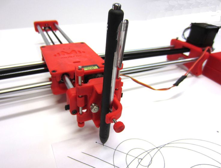 33
33
GRBL CNC pendant with Bluetooth link
Free
sleeve for acme cnc printer t8 nut
Free
Optical Limit Switches Endstop Mount X Y Z axes for cnc 3018 3024 3040 2410 max alu series
€4.75
cnc milling machine grbl arduino maker upgraded version
Free
cnc milling machine version 3.1.1 more resistant and robust
€4.21
CNC Shield 40mm Fan Clip
Free
3-Axis GRBL CNC stepper controller with Arduino Mega328
Free
CNC contoller for bCNC
Free
Case for Arduino UNO, CNC Shield and 60x60 or 40x40 fan (grbl).
Free
CNC Machine Parts
Free
Photon Printer - Micro Laser Engraver
Free
DIY CNC under $50
Free
A MACHINE THAT DESTROYS WHAT IT CREATES - Kinetic Sand Art Table
Free
Laser Carriage (Nikodem Dremel CNC)
Free
ARDUINO GRBL CABINET ARDUINO UNO CASE
Free
Sakul CNC v1.0
Free
My Plotter CNC Machine
€0.53
DIY Dremel CNC design and parts
Free
Cheap, Simple Pen Plotter and laser engraver
Free
EEZYxyDRAW
Free
BASICEXTRUD
Free
Lamp base for acrylic 3 mm
€1. 15
15
CNC GRBL NEMA 23
Free
GRBL CNC interface console
Free
Chip Suction for CNC 3018
Free
Controller Case for CNC 3018
Free
Easy 3D Printable CNC Drawing Machine - Draw on Cakes, Phones, Paper, Shirts | Arduino GRBL Plotter
Free
Dual Axis Motion System!
Free
CNC Alignment Collar for Dial Indicator (3020 3040 3060)!
Free
control panel for cnc grbl
Free
CNC machine Revision 3
€5
CNC Machine V3
Free
CNC Machine
Free
EEZYxyDRAW
Free
GRBL + SD Card + LCD Screen + Keyboard
Free
DIY 3D Printed Dremel CNC
Free
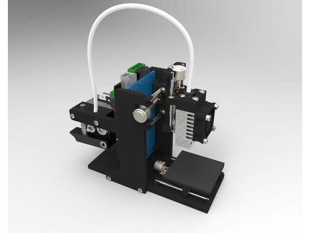
Cheap Arduino 3D Printer||Arduino-diy.
 com
com This article describes the construction of a 3D printer that costs around $60-70 (probably the cheapest concept in the world).
This 3D printer works with the cheapest motors on the market - 28Byj-48, Electronics - Ramps 1.4 controlled by Arduino.
The author of the project is a 16-year-old guy from Germany.
3D printer specifications:
Working space: 10x10x10 cm;
Speed: 20 mm/s;
Resolution (accuracy): 0.2 mm.
P.S. Under each section, in accordance with the table of contents of the article, photos are posted as a visual instruction
Mechanical part
MDF boards:
-1x 30x34 cm (Base).
-2x 6x4 cm.
-1x 34x6 cm.
-1x 15x4 cm.
- 2 GT2 pulleys + 1 m GT2 timing belt.
-10 bearings 624.
-1 pulley Mk8 for drive.
-1 PTFE tube.
Smooth rods for guides with a diameter of 8 mm:
- 2, 22 cm long.
- 4 x 17.5 cm long.
Local hardware store:
- 1 shaft with M5 thread, which you will cut into 2 pieces.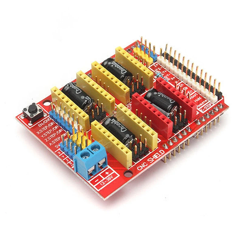
-2 M5 hex nuts.
- 8 screws M3x16 mm.
-6 screws M3x 25 mm.
-4 screws x M4x45 mm.
-2 screws M4x60 mm.
-4 screws M4x20 mm.
-20 M4 hex nuts.
-10 M3 hex nuts.
-12 small screws.
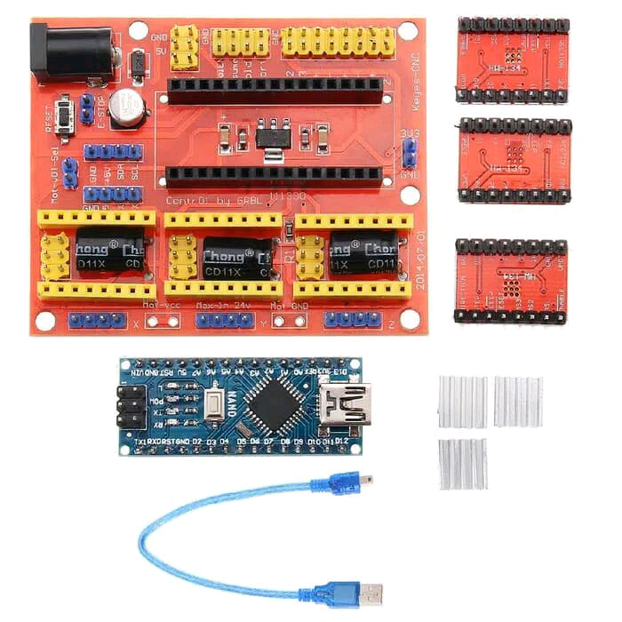
Electronics
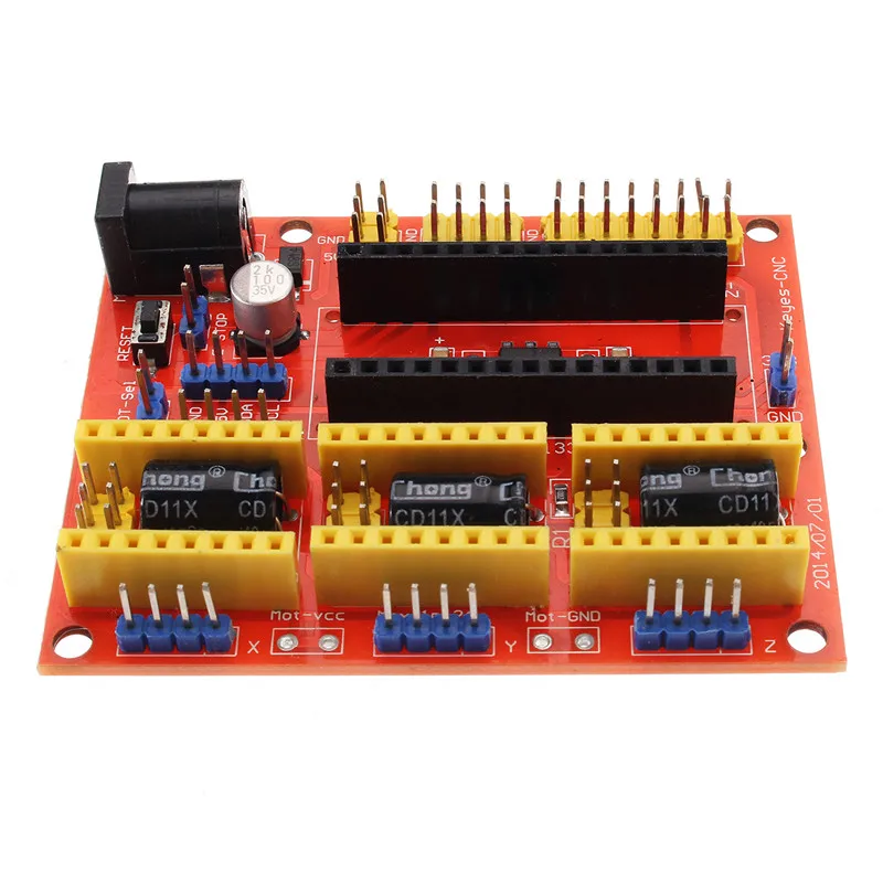
-1 Arduino Mega 2560 board + Ramps 1.4 + 4 A4988 stepper motor drivers.
-4 stepper motors 28byj-48.
-3 optical limit switches.
-1 Nema 17 stepper motor (we also order from Ali or Ebay. Such drives cost about 10 dollars).
Extruder tip:
-1 E3D-V5 Aliexpress extruder
or more expensive but with cooling
-1 E3D-V6 Aliexpress extruder.
Knots to be printed on a 3D printer
Download the latest versions of 3D models of units to be printed from the link: Thingiverse
.
2 "Z-Motor" parts
2 "Y-End" parts
2 "X-End" parts
1 "X-Carriage" part
1 "Motor" part
1 "Hotend" part
1 piece "Hotend Clamp"
Download mechanism for extruder here: Thingiverse.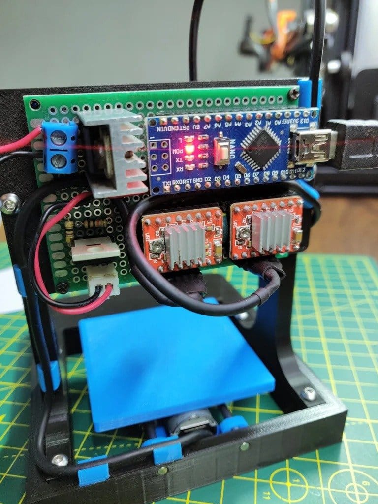
28BYJ-48 Stepper Motor Modification
In order to convert the 28BYJ-48 stepper motor from unipolar to bipolar, you need to open the plastic cover.
Then remove the red cable and open the contact track from it as shown in the figure.
Now at the other end is the output that you will connect to the Ramps, arrange the pins as follows:
blue--yellow--orange--pink
With this little modification, you can connect these motors directly to the pins provided on the Arduino Ramps 1.4 shield
Y Axis
First you need to glue two wooden boards together.
Then place the printed parts "Motor", "Z-Motor" on the wooden boards.
Then fix the printed parts with the screws.
Next step: fit the motors into the slots and then the LM8UU bearings.
Install the pulley on the motor and the 624zz bearings next to it.
Use plastic ties to secure LM8UU bearings.
Next - install two guide rails 17.5 cm long with a diameter of 8 mm.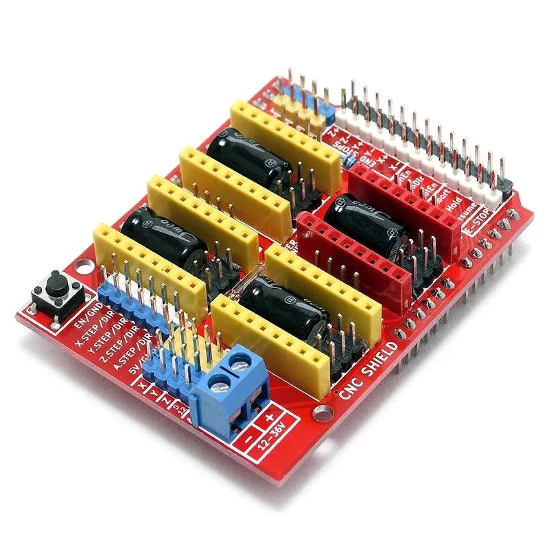
Finally, pull the belt through the "Y-ends" and install the limit switch.
X-Axis
For X-Axis you need:
Install two M4x45mm bolts in the "X-End".
Connect the motor as shown in the illustrations.
Tension the belt and install the limit switch.
Mount the extruder with two screws M3x25 and tighten with nuts.
Z Axis
In order to assemble the Z axis, you need:
Install LM8UU bearings in "X-Carriage" + "X-Ends".
Post install "X-Ends" + "X-carriage" on rails 17.5 cm (X-Axis) and 21cm (Z-Axis).
After that it is necessary to connect the threaded shaft with the motor
Printing table
We drill four holes with a diameter of 3 mm in a wooden plate 20x13 cm.
After that we tighten 4 bolts M3x25.
We assemble the entire 3D printer
We assemble it in accordance with the figures below. There is no point in giving additional explanations. The main thing is that the previous steps are correctly implemented.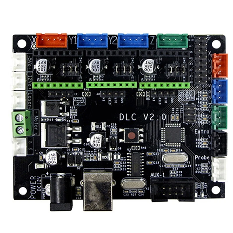 In this case, there should be no problems.
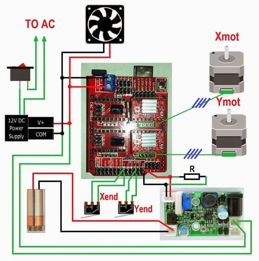
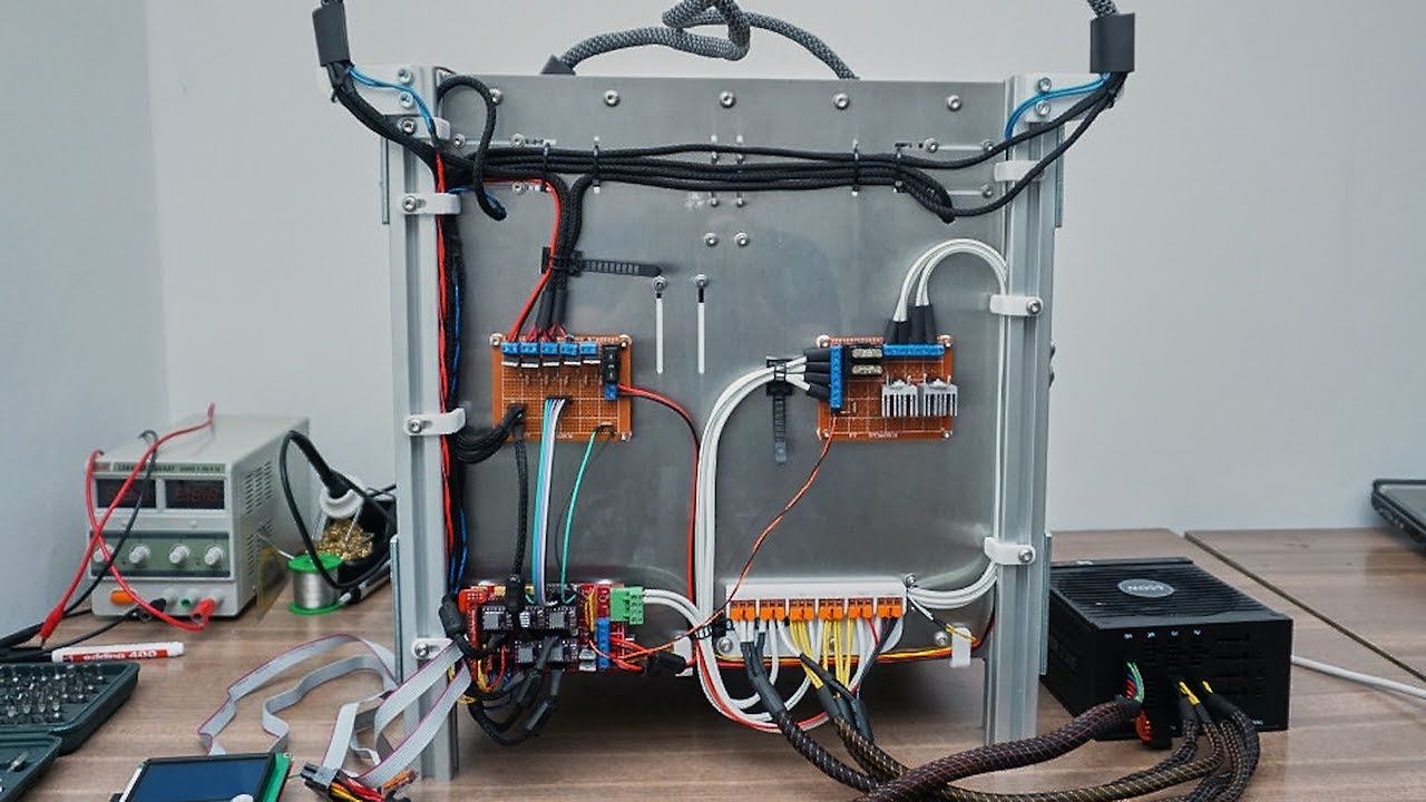
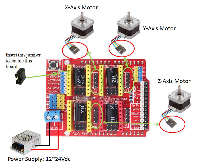
We connect electronics to the 3D printer
We connect electronics (including Arduino) in accordance with the figure below.
Software for Arduino
You can download the Arduino IDE configuration file from www.repetier.com.
This should be enough. You can carry out direct adjustment for your received design, dimensions, etc.
Photo of the printing process and results
After some calibration, good cube samples were printed with dimensions of 1x1x1 cm. As a result, there is a significant displacement of the layers.
So I recommend setting the A4988 to 1/16 microstepping and adjusting the current to the minimum value.
You can also play around with the Arduino firmware to get better results.
Leave your comments, questions and share your personal experience below. In the discussion, new ideas and projects are often born!
10 useful tips for working with a laser engraver on wood and plywood.
 Setting up a laser engraver.
 Hello everyone, Friends! 3DTool is with you!
CO2 laser cutting machine. 10 helpful tips for beginners on cutting and engraving plywood and wood.
Foreword. For part of the advice, it's important to understand the difference between vector files and raster files. Vector files are mathematical formulas that describe lines, circles, and so on. They are created in programs such as Adobe Illustrator, Inkscape, AutoCAD, and Corel. Raster files are collections of individual pixels, such as digital photos, Adobe Photoshop files, JPG files, etc. You can only laser cut vector files, but engrave both types. Some of the tips listed below require your file to be a vector file.
CNC Laser Catalog
Tip #1. Preparation for laser cutting or engraving.
Before we move on to cutting and engraving tips, let's start with some helpful tips for preparing for them:
Smoke/Slag Resistant: If you are going to engrave anything, remember that engraving smoke/smudge can stain the edges of the engraved surface.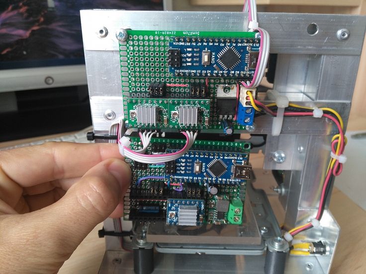 To avoid this, stick masking tape on the surface. It won't affect the power of the laser much (you can increase the power a little if you think it's necessary), but it will protect the material around the area being engraved from smoke trails. Once engraved, simply peel off the tape.
Presets: The laser machine you are using probably has the recommended settings for cutting or engraving different materials and different thicknesses. You can download these settings to your computer or the laser cutting machine control board directly and save them as presets. Be sure to name them something meaningful so that they can be easily identified in the future. So the next time you engrave leather or cut 3mm acrylic, you can simply find and use a preset to work with that material.
Test cutting workpiece: Even if you have a preset for material cutting, it is recommended to perform a test cut before starting the main job. There is nothing worse than taking out a sheet of plywood material after a laser cut and discovering that it did not cut all the way to the end.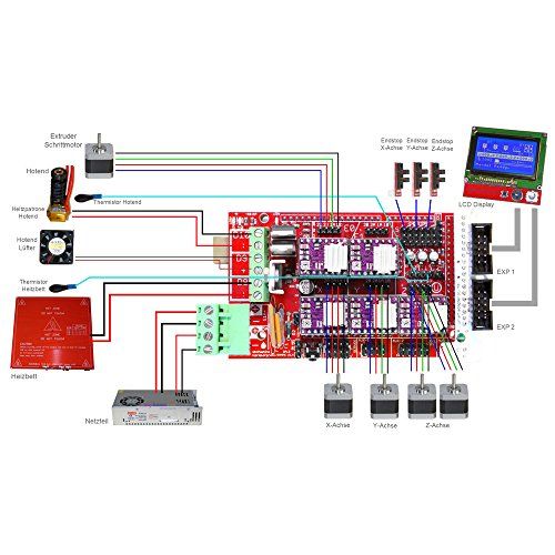 We recommend creating a small circle or square (about 6 or 10 mm wide) and cutting it into the corner of the piece. In this way, you can see if you need to increase or decrease the power before starting the base job.
Tip #2: The Importance of Layers in Image Editors
Some of the tips below require the ability to engrave/cut only part of a file or design at a time. The easiest way to do this is to put different parts of your design on different layers of the same file. Most graphics programs allow you to create layers and then turn them on and off. While you can of course put everything on one layer, having multiple layers gives you several key benefits:
1 . Cut order control. Your laser machine will most likely have several options for controlling the order in which cuts occur, but the most convenient way to control the order is in one single way: set different cut lines on separate layers to turn each layer on and off in the desired order.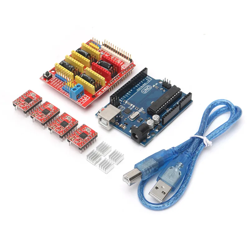
2 . Multiple layers in one file. Instead of saving each design or part of the design in a separate file, just put them all in one file and break them into separate layers. Then just run the desired layers.
3 . Create hints and targets. Perhaps you've created a few clues to lay out your design, or a target for placing multiple identical objects. To prevent them from being cut out on the main design, put them on a separate layer and just turn it off.
Tip #3: Laser cutting and wood engraving techniques.
Let's say you've designed a logo or image and want to carve it into solid wood. Wood is a great material for engraving, but you need to understand the difference between engraving on a solid piece of wood and a composite material like plywood or MDF. Unlike manufactured material, natural wood is not homogeneous. The fibers in wood represent different stages of growth (winter and summer) and each will burn differently.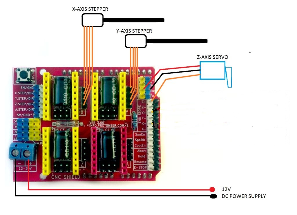 Usually the dark fibers are harder and the light parts in between are softer. As you can see from the sample photo above, you see a zebra in the engraving. If a uniform engraving is important to you, your best bet is good plywood, where the top layer is more predictable.
Another thing to keep in mind is materials with a thin veneer of good wood on top. Engraving often burns through thin veneer, exposing what lies underneath. Make sure the wood underneath the veneer looks good and that you burn all the veneer out so you don't have a mixture of veneer and surface underneath.
Tip #4: Laser cutting overlapping objects.
Often, when you need to cut several parts at the same time, it is tempting to place them next to each other so that adjacent identical lines overlap each other to save a sheet of material. It's a good idea, but it can be messed up very easily.
For example, you have a bunch of squares for cutting. If you draw two squares (four sides each) and then press them together, there will only be visually one line between them.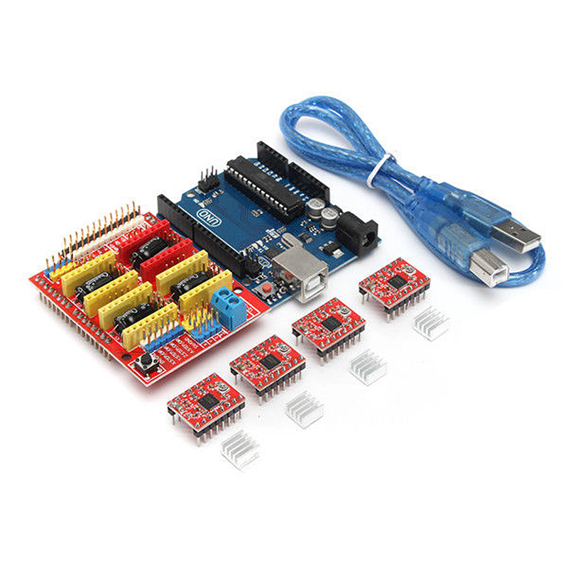 The problem is that although it looks like one solid line to you, the computer still sees two. The end result is that the lines will be cut off one by one. This will cause that edge to be more likely to be scorched rather than clean. It will also waste time on an unnecessary cut.
The way to fix this is to remove one of the doubled lines. Draw one of the squares 3 sided, deleting one side line opposite the first square and align them.
Tip #5: The difference between bitmap and vector laser engraving.
The main difference between raster engraving and vector engraving is that for engraving, the laser moves from left to right across the engraving area and then moves down a minimum step, repeating until the image is engraved. With a vector cut, the laser simply moves along the lines. As a result, raster engraving takes much longer than vector engraving.
So, you have a drawing. For example, the Celtic knot, which is basically just lines. Of course, you can run it as a bitmap engraving. The advantage is that you can set the thickness of the lines to whatever you want, and different lines will have different thicknesses. The downside is that engraving will take much longer.
If the file is vector, there is a quick way to create lines without cutting them. Run your file as a vector cut, but turn off the power and increase the speed. For example, to cut through 3mm plywood, we set the laser power to 100% and the speed to 20%, but to draw a line on it, we reduce the power to 30% and the speed to 95%. Trying to cut through the material, the laser simply burns a thin line on it. The advantage is that this will be much faster than vector engraving. The downside is that the line will be very thin and you won't be able to change its thickness.
Tip #6: Defocus the laser beam for thicker vector lines.
In the last tip, we looked at how to use a vector image to simply draw lines on material to create line art or designs.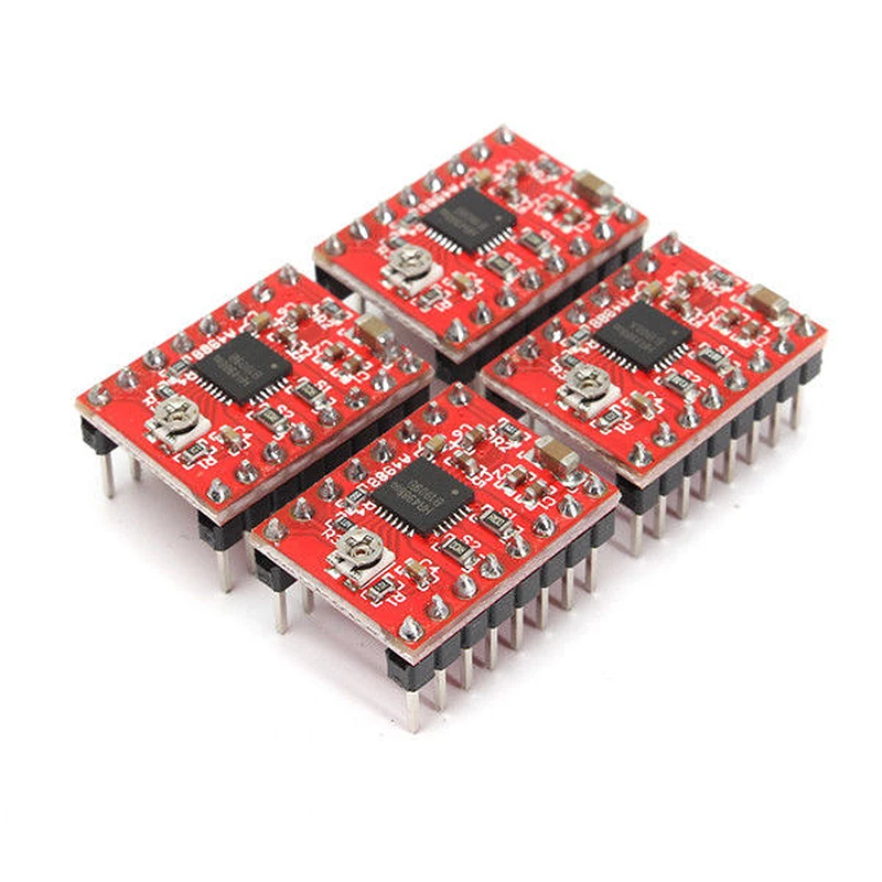 But the disadvantage of this method is that the line is very thin. But there is a way to get thicker lines. The laser beam has a very narrow focus point, so if you lower the material a little, the laser will lose focus and scatter. Lay a small piece of wood about 9 inches thick.5mm on the material you are using and focus the laser on that piece. Then run the laser at the vector setting (lower power and higher speed). The result is a much thicker line than if the laser were correctly focused.
There are 2 drawbacks to this method that you need to be aware of when using this working technique. One of them is that the line is a little inaccurate and not as sharp as with a raster engraving. Secondly, at the corners of the lines, the laser pauses a little as it changes direction, so the corners burn a little deeper. The corners look like they have little dots in them.
Tip #7: Adding a vector stroke to the edge of a font or engraving image
You should usually get good edges on any engraving your laser does (unless you are checking focus).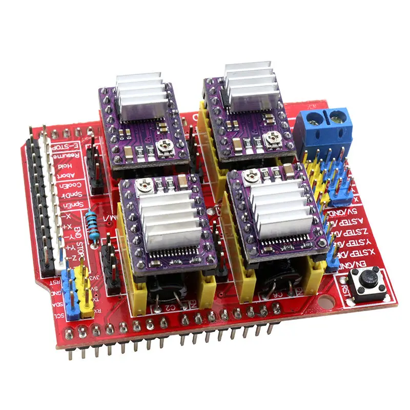 But if you want to sharpen the edges of the engraving a little more, here's a good tip: add a light vector stroke around the edge of the engraved image.
You will need the image as a vector file. Select it and add a thin stroke (stroke) around the edges. When you set up the laser for stroking, turn down the laser power and increase the speed so that it burns but does not cut through the edges. After the laser has done its basic engraving, it will come back and burn a thin line around the very edge.
This effect is great for all kinds of inscriptions.
Catalog of desktop laser machines - https://3dtool.ru/category/chpu/lazernye-stanki/lazernyy-graver/
Tip #8: Laser cut wood in the target area.
Sometimes you need to accurately hit a target area that is not at the laser's start coordinates. For example, there is a piece of plastic from which you have already cut out several shapes, but there is enough space between the old cutouts to make another, new cutout.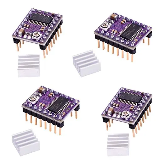 How can you neatly insert a new cut into the remaining space?
First measure the target area and get its approximate dimensions. Make sure there is enough space for what you want to cut out. Then place the workpiece on the honeycomb table of the laser machine and measure the distance from the zero coordinates of the laser to the target area. For example, a rectangle 2.5cm by 5cm, located 6cm below and 2cm to the left of the edge. Then, in your file, use markup to highlight the target area and position from the origin of the material. Place your drawing or cut in the target area. Make sure that this marking will not be used when cutting. If you measured everything correctly, your notch should be right in the target area.
Tip #9: Laser Engrave Many Objects Simultaneously and Use Templates.
Let's say you have a lot of wooden coasters that you want to engrave your logo on.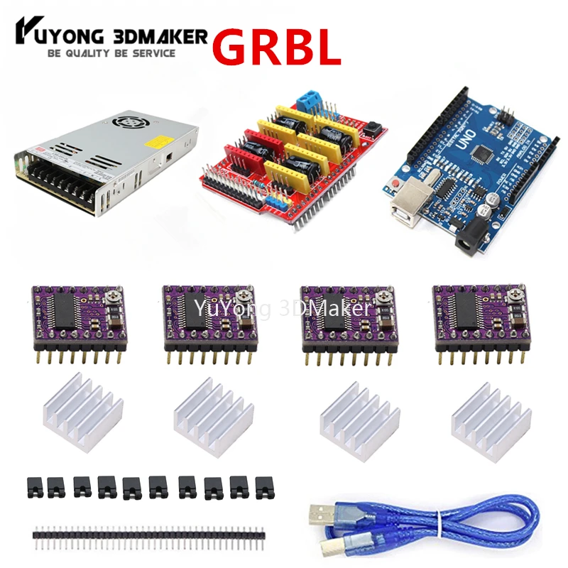 You can place them one by one at the laser start coordinates and engrave one by one. But wouldn't it be better to arrange several pieces at the same time and have the laser cutter engrave the image on all the blanks at the same time?
The trick is to create a grid on which you can lay out the blanks and precisely laser engrave them. Create a new vector file the size of your laser target area. Then measure your image to be replicated on blanks. If you can get it's exact shape this is a great option, but if that's not possible then a regular circle or square will do, as long as the edges of the image fit exactly into the area of the square or circle. This will be your target form. Create a template and place your design (engraving or cutout) in this area. Now copy the template and your drawing and paste as many copies as you can fit within the laser's workspace.
Tip: Leave some space between the templates so that the blanks do not lie tightly together.
Before you run the file, don't forget to move the grid and template to one layer and your image to another layer. Then turn off printing for the layer with your design on it.
Cut a piece of cardboard/plywood to fit the laser area and place it in the laser. Now make sure only the template layer is set for cutting. Engrave the template on cardstock. You will get a grid that matches the one in the file. Now place the items you are going to engrave on the template marked on the cardboard. Remember to refocus the laser on the top of what you are about to engrave. Now you can disable printing of the target layer and enable printing of the layer directly with the design.
As long as you don't move the cardboard/plywood, you can just keep laying out new pieces on it, click on the engraving, and repeat until you've done all your work.
Catalog of large laser cutting machines: https://3dtool.ru/category/chpu/lazernye-stanki/lazernyy-gravirovalnyy-stanok/
Tip #10: Use a laser dot to simulate a job without cutting.
Some laser machines have the ability to turn on the laser pointer, which projects a red dot indicating where the laser beam will work.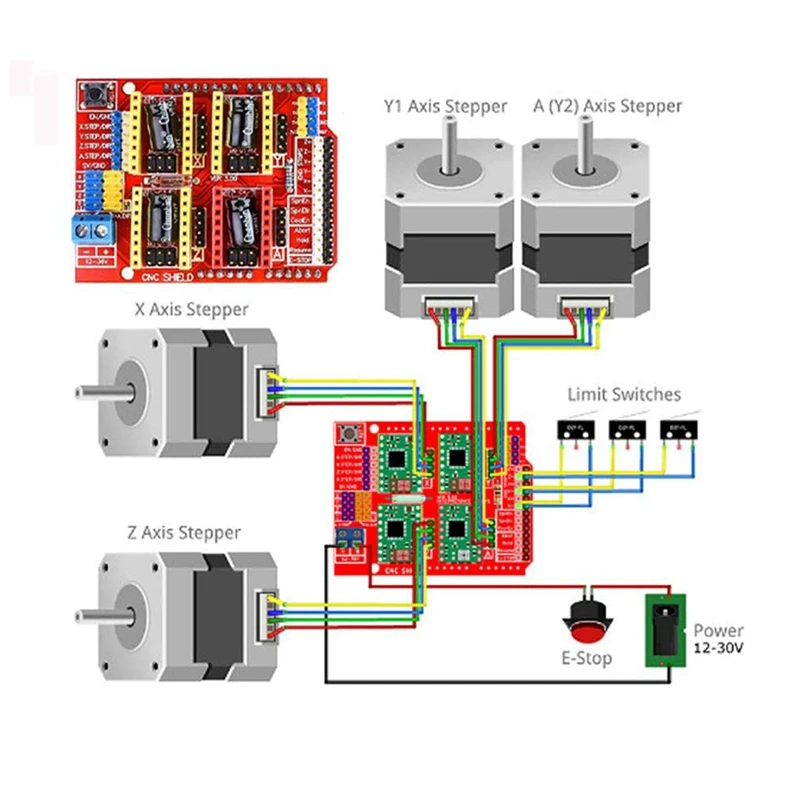 This is useful for determining where the laser will cut before working on the material itself. Just turn off the laser power and turn on the red dot. Then run the file and see how the red dot moves, as if we were running a task in idle mode.
One thing to keep in mind is that this method works well with vector lines where the laser/red dot follows the lines, but not so well with engravings where the laser goes back and forth across the engraving area. If you need to use a red dot to figure out where the engraving ends, you can draw a square or circle around the image you want to engrave, and then simply use the red dot to trace around that square in vector mode. Or, you can draw a horizontal and vertical line from the center, as in the picture above.
Well, that's all we have! We hope this article was useful for you!
You can contact us in any way convenient for you:
• By email: [email protected]
• By phone: 8(800)775-86-69
• Or on our website: http://3dtool.