How to make 3d printer with arduino
How to Make a 3D Printer with Arduino – ELEGOO Official
Source: https://unsplash.com/
3D printing technology is wide, despite having been around for a little over 30 years. The improvements the technology has been undergoing are all slowly pushing it slowly towards a realm where everyone will be able to access simple 3D printers at low prices, getting the ability to make whatever they want from the comfort of their own homes. One of the most utilized 3D printing concepts is the Arduino.
Arduino is an open-source electronics platform that is based on easy-to-use software and hardware. They are boards that have the ability to read inputs, activating other machines, among many other automated functions. We are going to explore how to make a 3D printer using the Arduino platform, the benefits of having a DIY Arduino printer as well as some comparisons with other official models that are in the market.
Why Arduino?
Source: ELEGOO
There are perfectly good reasons why Arduino is used extensively in most DIY projects of making 3D Printers. The first Arduino kit was created in 2005, and in the last 15 years, it has become a very reliable software for people who are looking to create their own 3D printer. The following are reasons why they are the best choice for DIY 3D Printers.
- It is cheap: Arduino is easily accessible and affordable, and the price keeps going down as more improvements are being made in the 3D printer sector. A simple Arduino kit will set you back just about $24, which is well within the affordable range of most people.
- Easy to use: An Arduino kit is usually ready to use straight from the box. The kit comes in a complete package that includes a 5V regulator, a burner, a microcontroller, a serial communication interface, LED, and headers. All you have to do is plug it into the USB port of a computer, and you are ready to roll.
- Wide range of codes: Arduino comes with a huge library of codes that are already present in the Arduino itself. The kit literally sets itself up in a number of ways, and in the event, you run into obstacles, troubleshooting is not that complicated to pull off on your own.

- Large community: There is a huge number of online forums that are full of people who use Arduino, and this provides new users with a platform where they can get help immediately from other users who have had the experience already. Every trouble you may run to will have a solution, and this makes Arduino a very resourceful tech.
- Cross-platform: Arduino is a cross-platform software that can be used on Windows, Linux, and Mac. This makes it resourceful and unlimited in many ways. You don't have to buy a particular computer to run it; all you need is to get a computer with the right specs. You will be making your 3D models in no time.
Making a 3D Printer with Arduino
The process of making a 3D printer may look daunting for those that have never used it before, but if you are a newbie to the game, the process is a little easy.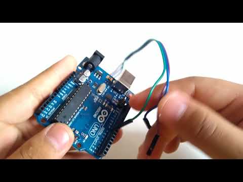 The following are some of the stages that are used in making a 3D printer using the Arduino platform.
To start off, you have to start collecting the components and supplies to start yourself off. The following are the boxes you have to tick off.
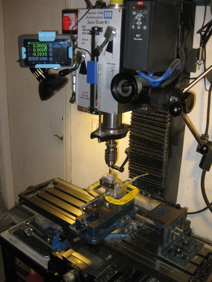
- A ramps 1.4 controller board: This is used for interfacing purposes like connecting the end-stop switch, the heatbed, the stepper motor driver, the hotend, and a host of other components with the Arduino.
- Optical end-stop switch: This is a sensor switch that comes with two markings. NO or NC (Normally Open/Normally Closed). They function as triggers when the XYZ axis of a printer reaches its endpoint. They can be used at any time to stop and start movements.
- NEMA 17 stepper motor: This is a motor that allows the user to set the speed of revolutions for the movable parts of the printer. The average motor has about 200 steps, but you can get a bigger one.
- PCB heatbed: This keeps the extruded plastic parts warm at all times to prevent them from warping.
- Power supply: A 12V/20A power supply is needed to run a simple kit. These power metrics are the minimum you should go for success.
The Process
With all the important components in place, the next step is to start making your DIY 3D printer. The stages involved include the following.
Step 1: Build the Frame
Source: https://www.pinterest.com/
The frame is the outer casing that houses the entire contraption, and it can be made to any size depending on what you need. The materials used to make the frame also vary, and the decision comes down to personal preference. The most compliant used materials are aluminum, acrylic, or hardened plastic. You have to make sure that all the parts fit well and there are no loose parts. It is important that the frame is solid because it will be providing support to the other parts that are added.
Step 2: The Display
Source: https://www.pinterest.com/
An LCD display is important as it relays the information you need to know about the printing process in the absence of a computer connection.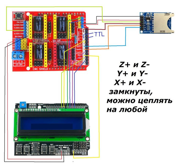 You need an aluminum sheet for this process with some holes and screws, and nuts. You have to cut out space into the aluminum sheet through which the display screen will pop out of. Once you have all that art covered, connect the necessary display cables from the inside leading out, waiting for the main part of the printer to be installed.
Step 3: Preparing the Y-axis and Z-axis
Source: https://www.pinterest.com/
You need an MDF base that houses a cooling fan to reduce the heat produced by the stepper motor. These are done by adding two wooden cuttings for the X-axis placement. This is followed by making the Y-axis placement that’s supposed to be at 90 degrees from the X-axis. Hold them in place using glue, or you can simply use some screws.
You have to add a stepper motor to the X-axis using two pieces of sliders of any length that can fit within the structure. Once the slide is screwed in place, fit your wooden mount for the hot-end, the cooling fan, and the PTFE tube.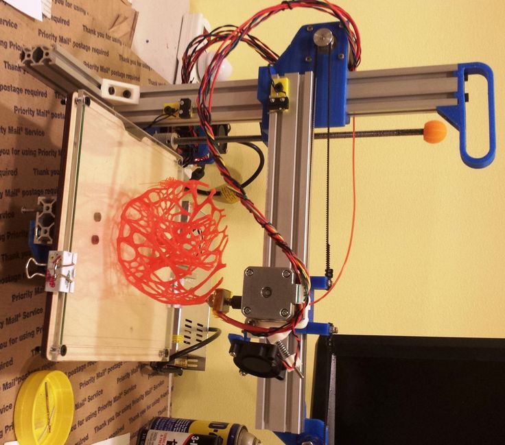 With these two in place, your 3D printer is starting to take shape.
Step 4: Preparing the Bed
Source: https://www.pinterest.com/
The bed is one of the most important parts of the entire machine. It is the part that provides the platform upon which the model being printed is made. It can be made out of glass or an acrylic sheet held down by screws. You can have the base supported by another solid material. Once all that is done, place the bed on the Y-axis, and it is ready to start rolling.
Step 5: Make the Connections
Source: https://www.pinterest.com/
The next part involves making the wiring connections of all the components that you have already laid down. All the electrical components like the ramps. The drivers and the power supply have to be linked properly for them to run as designed. To avoid entangling the wires, make sure you deal with one connection at a time, ensuring that they don’t cross each other unless there’s no other way around it.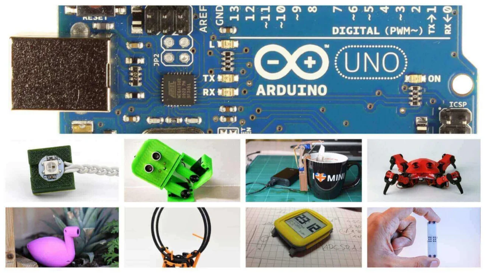
Step 6: Make Alignments
The bed you created earlier has to align with everything else, or you may experience a lot of trouble getting the models right. Start by aligning your bed, rotating it clockwise and counterclockwise until you create some space between the hot-end tip and the bed. The margin of error should be between 0.5mm to 1mm. Anything larger than that will have the printing guy misfiring.
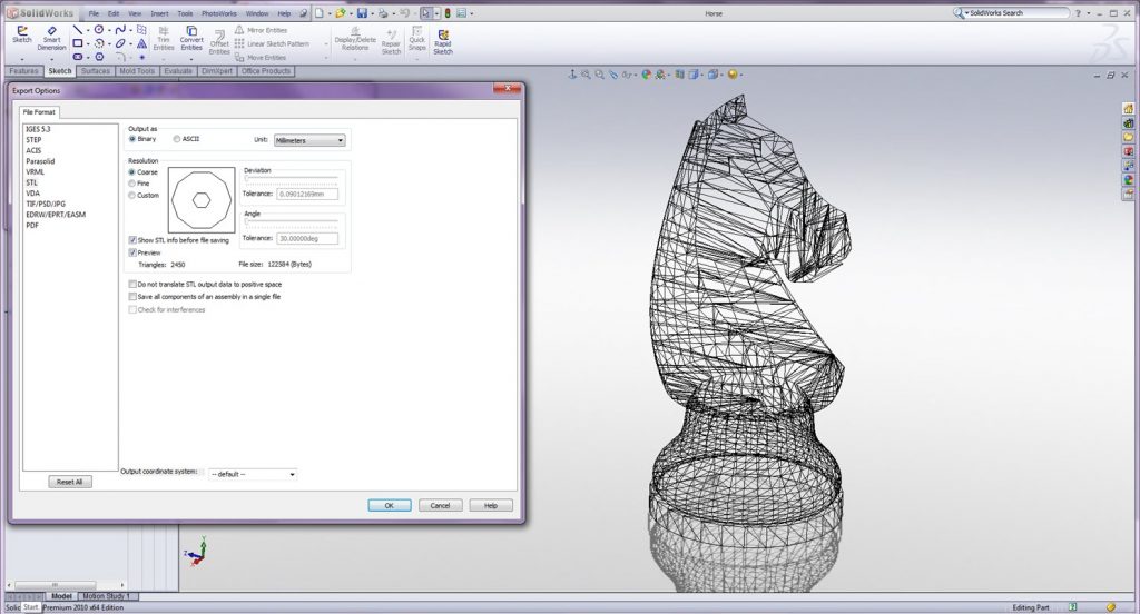
Step 7: Programming
Source: https://www.simplify3d.com/
With all the hardware installed and the electrical wiring and cabling in place. It is time to install the brain of the whole operation. Programming the 3D printer doesn’t require you to code from scratch. The software simply needs to be installed on the computer connected to the machine. This should not take too much of your time.
Step 8: Run the Machine
Once the 3D Printer program is installed and the components are set, it is time to run the machine for the first time to finger out if it is working as designed or whether it needs some more tinkling. The number of software that you can use to model your objects is many; you are free to choose the one that works best for you and switch the machine on for the first test run. Make sure the fan is working to deal with the heat.
Building Your Own 3D Printer. Is It Worth It or Not?
Source: https://www.pinterest.com/
Having established that making your own printer is possible, and having seen the process and what it takes to attain success, the question now is, is it worth the trouble? High-quality 3D printers cost less than $400 these days, and as much as making your own brings pride and cuts costs significantly, how do DIY 3D printers hold against professionally manufactured ones? To better get to the answer, the following are the pros and cons of DIY 3D Printers.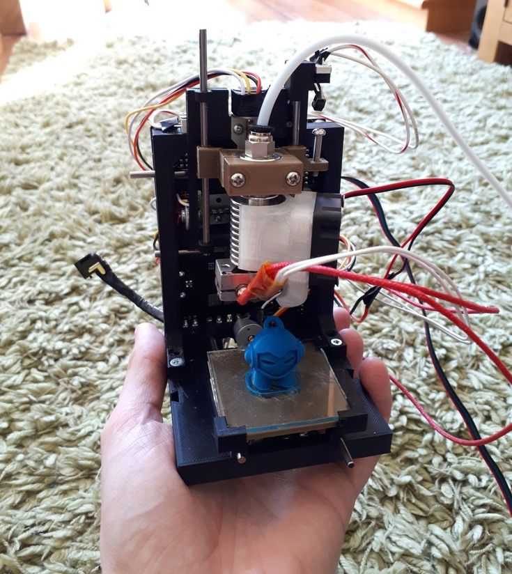
Pros
- DIY Kits are cheap and easy to access. For as little as $25, you can have a full package that can help you set up your own printer.
- DIY projects will make you understand 3D printing more, adding to your experience on the subject, which increases your level of knowledge and chances of success if you ever think of getting fully immersed into the industry.
- It is fast if you know what you are doing and you have all the materials you need in one place.
- There’s a huge online community of DIY 3D printer enthusiasts, and these platforms provide resources that help people learn more about 3D printing.
- The kits come with instruction manuals that anyone can follow and hack the construction. They are very easy to use.
Cons
- You still need some basic knowledge of assembling electronic parts in the right way to be able to put 3D printers together. You can’t wake up one morning and decide to make it because you feel like it.
- They are not as high quality as those that have been manufactured by proper 3D makers. The parts found in DIY printers are too rough and rudimentary for the machine to produce superior products.
- There are very many things you may miss along the way, and this can end up frustrating you later on as that will force you to retrace your steps backward until you find the source of the malfunction. That will waste a lot of your time.
- You will always need to buy more parts the furthest along you go. There’s also the disadvantage of the parts falling apart since they're not well optimized for such an intense process. You will need replacements much faster.
- There are limitations when it comes to software configurations and upgrades since the hardware is not optimized for the software you may choose to go with. You may end up using the same software for years, and that will limit the things the printer can pull off.
Roughly, you may end spending between $100-$200 making your own DIY 3D printer.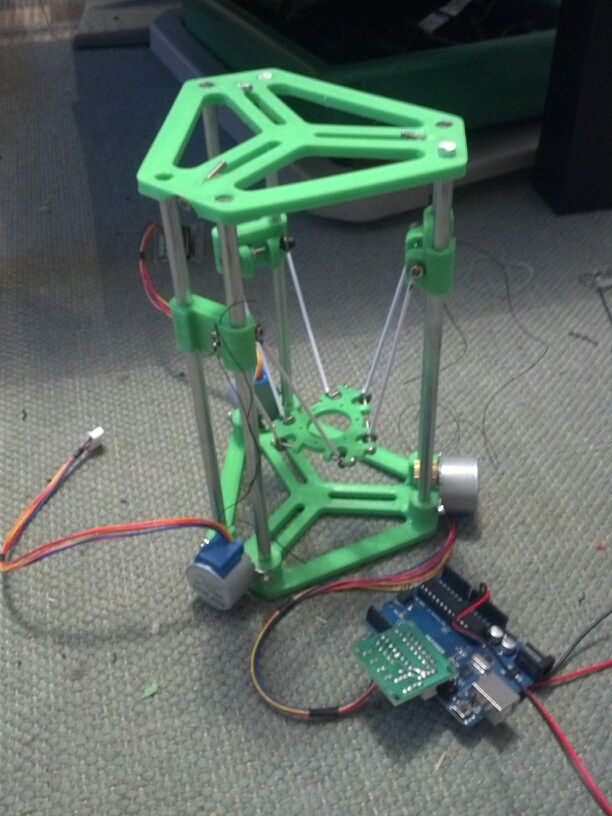 That cost may be cheaper than the standard prices for a professionally made printer, but when you weigh the strengths and weaknesses of each, the DIY is at a disadvantage. Therefore, on the question of whether to go for a DIY 3D printer or simply buy a good one, the answer comes down to what you plan to do. If the thrill of making your own is what is important, then take the DIY route. But if you want to get some professional work done, then you are better off adding that extra $200 and getting a proper 3D primer with accessories and software updates.
There are some things you have to pay attention to when going the DIY route, factors that will determine the success or the failure of your project. Some of them include the following.
- The size of the printer you intend to make
- The printer type (Cartesian vs. Delta)
- Extrusion type
- The cost
- Availability of liquid polymers
- Software compatibility.
Before you embark on setting anything up, you have to first determine whether all the conditions mentioned above are met; only then will you get anything done by coming up with a good plan.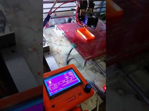
Conclusion
DIY 3D Printers are effective if they are made in the right way, and there are many methods of creating them. Finding a good Arduino kit could be the difference between having a 3D printer that world and one that keeps breaking midway. Ensure you do some background research before having to gain more knowledge before committing yourself to an ambitious project like this one.
For more information on how 3D printers work, the accessories they need to function properly, and the current trends in the industry, check out our website, and you will have access to a huge pool of resources and expert advice.
Everything You Need to Know to Get Started With Arduino
Published on September 30, 2021 by Mikahila L.
The open-source 3D printing maker community is ever-evolving as new tools innovate the space. One such tool is an Arduino— a programmable circuit board that is often referred to as a microcontroller. Arduino launched in 2005 as a tool for students at the Interaction Design Institute Ivrea, Italy, with the goal of providing an inexpensive and easy-to-use device for novices and professionals to be able to create devices that interact with their environment using sensors and actuators.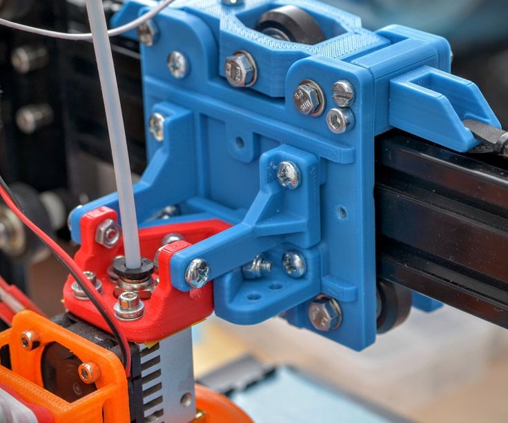 Now the company makes a variety of boards as well as accessories that heighten the board’s processing power. Let’s take a dive into all the things an Arduino board can do.
What is an Arduino?
Arduino is the name of a company that produces microcomputers that are popularly known as Arduino boards, or simply an Arduino. These boards come in a variety of models that offer different features, such as WIFI or Bluetooth for instance. The most popular microcomputer board by Arduino is the UNO. For less than $30, the Arduino UNO board is a powerful piece of hardware capable of processing a broad range of data inputs.
Arduino UNO board. (Photo Credit: Unsplash)
A microcontroller is a small computer processor that is mounted on an Arduino board along with different components that process the inputs and outputs. On the micro-controller you can, for example, you could have a variety of input options, such as a button or photosensor, send information to the computer processor and after analyzing the input then the computer processor sends output to any connected devices—such as a 3D printer.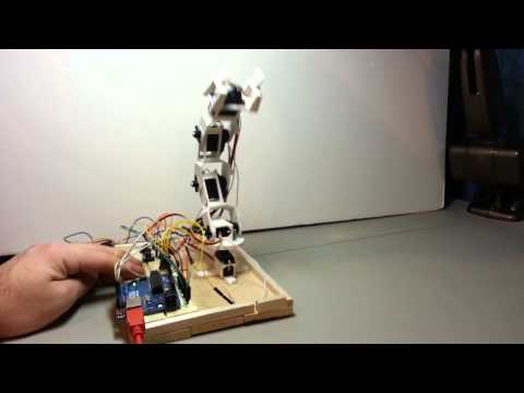 Since the board is open-ended on the frontend and as well as the backend, this allows you to have any myriad of inputs controlling any outputs.
How Do You Control an Arduino?
To control the board, you can use the USB port that is included on the board and connect it to a laptop, desktop, or 3D printer. Using the Arduino development environment on a desktop or laptop, you can write C++ code that is sent to the board through the USB port. You can remove the USB connection, then each time you turn on the board the code will run continuously in a loop.
Stack of shields. (Photo Credit: Arduino Forum)
On the board, you can have analog or digital inputs. For instance, if you have an on/off button, that would be a digital input. Whereas a dial that is tuned to varying degrees, for example, would be an analog input. Using the available header pins on the board, you would connect devices to the analog or digital inputs. You can purchase what is known as a shield for your board, which will allow you to add more functionality to your board. You can stack several shields on top of each other to add even more functionality.
Arduino Project Ideas
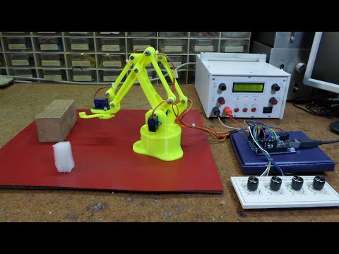
Since the company open-sourced the design of the board, your first project could possibly be to build your own microcomputer board piece by piece instead of buying a complete board from the brand. Next, you can build your own 3D printer on an Arduino board—there are plenty of inexpensive (under $100) 3D printer kits to get started with. Additionally, similar to Raspberry Pi, there are a number of other interesting projects you can do with 3D printing and Arduino. For example, users have created robots, robotic arms and even products for the home like automated door locks or dog treat feeders. You can learn more about Arduino boards HERE.
(Photo Credit: Unsplash)
Have you used Arduino for your 3D printing project? Let us know in a comment below or on our Facebook and Twitter pages. Don’t forget to sign up for our free weekly newsletter, with all the latest news in 3D printing delivered straight to your inbox!
Cover Photo Credit: Unsplash
Cheap Arduino 3D Printer||Arduino-diy.
 com
com This article describes the construction of a 3D printer that costs around $60-70 (probably the cheapest concept in the world).
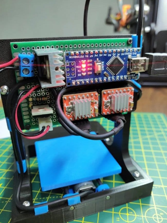
This 3D printer works with the cheapest motors on the market - 28Byj-48, Electronics - Ramps 1.4 controlled by Arduino.
The author of the project is a 16-year-old guy from Germany.
3D printer specifications:
Working space: 10x10x10 cm;
Speed: 20 mm/s;
Resolution (accuracy): 0.2 mm.
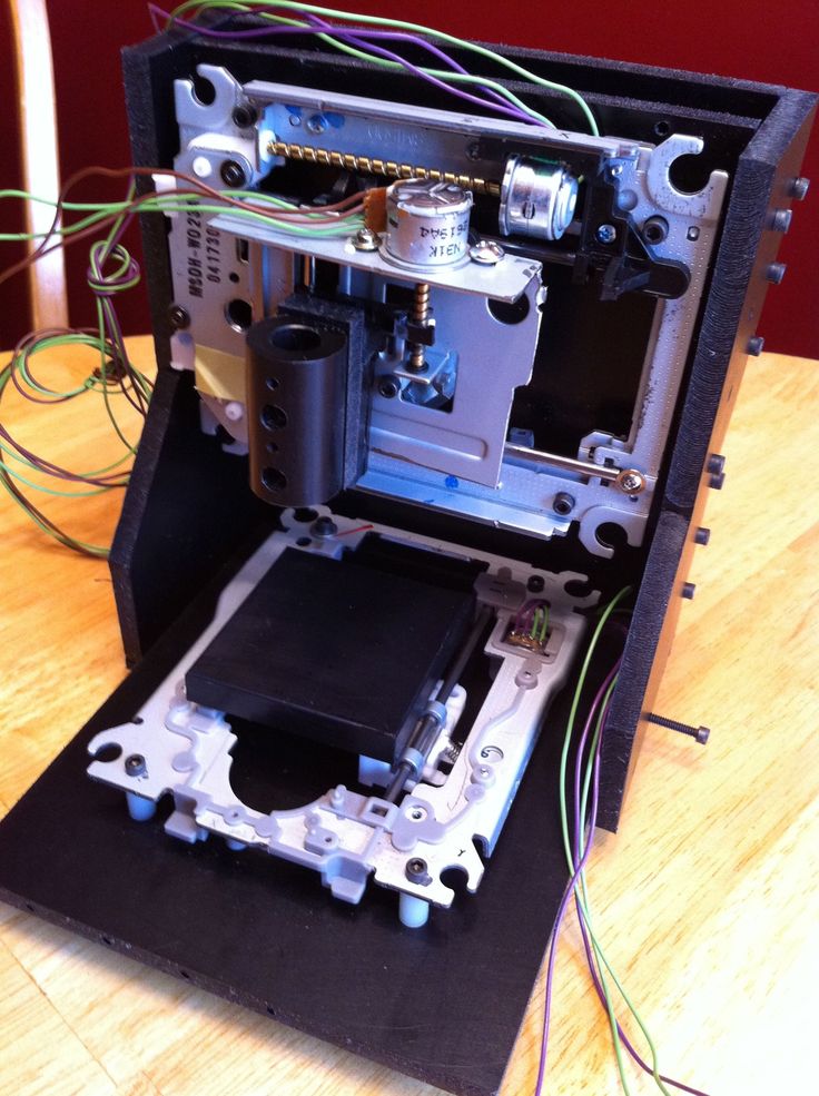
P.S. Under each section, in accordance with the table of contents of the article, photos are posted as a visual instruction
Mechanical part
MDF boards:
-1x 30x34 cm (Base).
-2x 6x4 cm.
-1x 34x6 cm.
-1x 15x4 cm.
- 2 GT2 pulleys + 1 m GT2 timing belt.
-10 bearings 624.
-1 pulley Mk8 for drive.
-1 PTFE tube.
Smooth rods for guides with a diameter of 8 mm:
- 2, 22 cm long.
- 4 x 17.5 cm long.
Local hardware store:
- 1 shaft with M5 thread, which you will cut into 2 pieces.
-2 M5 hex nuts.
- 8 screws M3x16 mm.
-6 screws M3x 25 mm.
-4 screws x M4x45 mm.
-2 screws M4x60 mm.
-4 screws M4x20 mm.
-20 M4 hex nuts.
-10 M3 hex nuts.
-12 small screws.
Electronics
-1 Arduino Mega 2560 board + Ramps 1.4 + 4 A4988 stepper motor drivers.
-4 stepper motors 28byj-48.
-3 optical limit switches.
-1 Nema 17 stepper motor (we also order from Ali or Ebay. Such drives cost about 10 dollars).
Extruder tip:
-1 E3D-V5 Aliexpress extruder
or more expensive but with cooling
-1 E3D-V6 Aliexpress extruder.
Knots to be printed on a 3D printer
Download the latest versions of 3D models of units to be printed from the link: Thingiverse
.
2 "Z-Motor" parts
2 "Y-End" parts
2 "X-End" parts
1 "X-Carriage" part
1 "Motor" part
1 "Hotend" part
1 piece "Hotend Clamp"
Download mechanism for extruder here: Thingiverse.
28BYJ-48 Stepper Motor Modification
In order to convert the 28BYJ-48 stepper motor from unipolar to bipolar, you need to open the plastic cover.
Then remove the red cable and open the contact track from it as shown in the figure.
Now at the other end is the output that you will connect to the Ramps, arrange the pins as follows:
blue--yellow--orange--pink
With this little modification, you can connect these motors directly to the pins provided on the Arduino Ramps 1.4 shield
Y Axis
First you need to glue two wooden boards together.
Then place the printed parts "Motor", "Z-Motor" on the wooden boards.
Then fix the printed parts with the screws.
Next step: fit the motors into the slots and then the LM8UU bearings.
Install the pulley on the motor and the 624zz bearings next to it.
Use plastic ties to secure LM8UU bearings.
Next - install two guide rails 17.5 cm long with a diameter of 8 mm.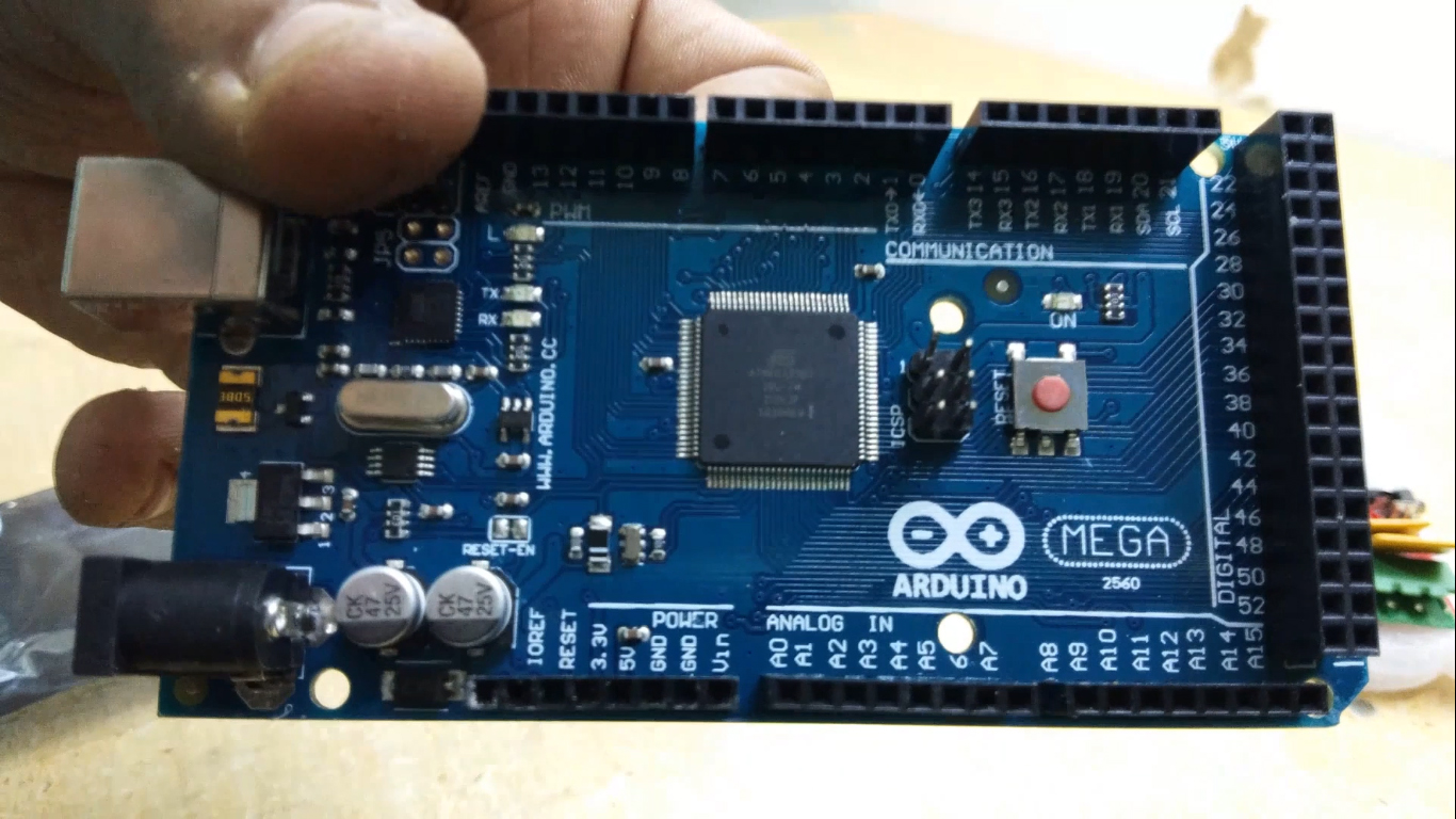
Finally, pull the belt through the "Y-ends" and install the limit switch.
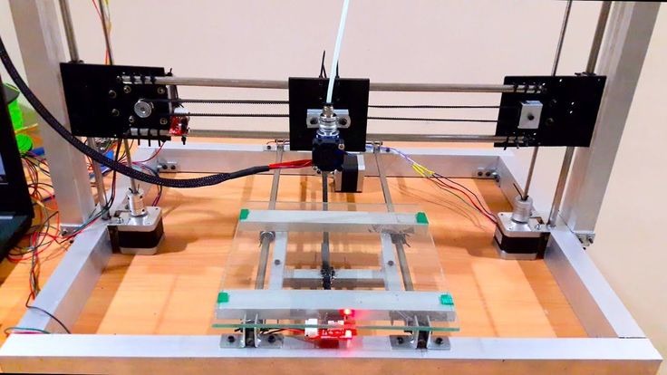
X-Axis
For X-Axis you need:
Install two M4x45mm bolts in the "X-End".
Connect the motor as shown in the illustrations.
Tension the belt and install the limit switch.
Mount the extruder with two screws M3x25 and tighten with nuts.
Z Axis
In order to assemble the Z axis, you need:
Install LM8UU bearings in "X-Carriage" + "X-Ends".
Post install "X-Ends" + "X-carriage" on rails 17.5 cm (X-Axis) and 21cm (Z-Axis).
After that it is necessary to connect the threaded shaft with the motor
Printing table
We drill four holes with a diameter of 3 mm in a wooden plate 20x13 cm.
After that we tighten 4 bolts M3x25.
We assemble the entire 3D printer
We assemble it in accordance with the figures below. There is no point in giving additional explanations. The main thing is that the previous steps are correctly implemented. In this case, there should be no problems.
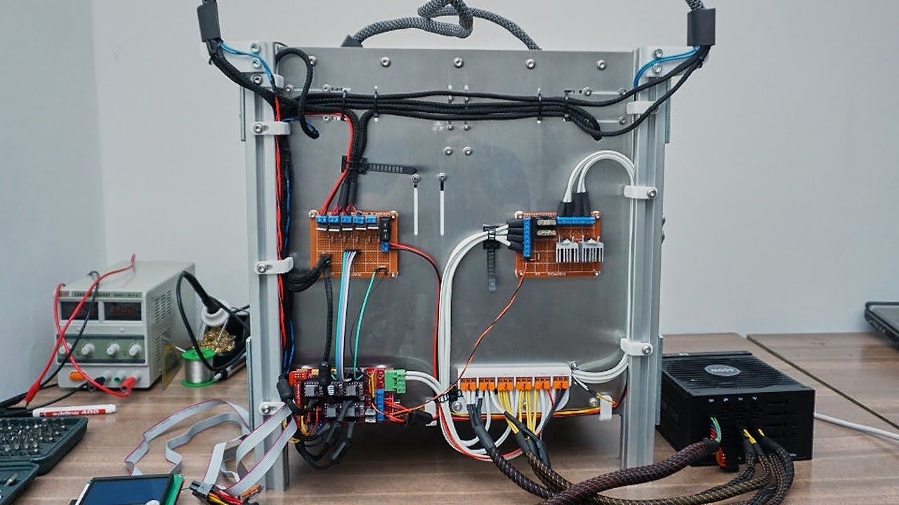
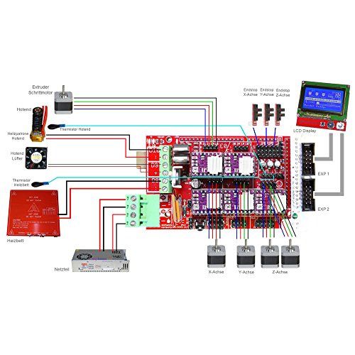
We connect electronics to the 3D printer
We connect electronics (including Arduino) in accordance with the figure below.
Software for Arduino
You can download the Arduino IDE configuration file from www.repetier.com.
This should be enough. You can carry out direct adjustment for your received design, dimensions, etc.
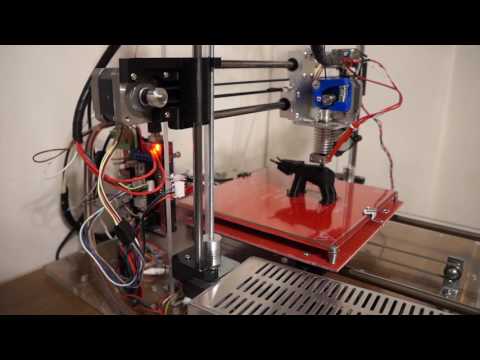
Photo of the printing process and results
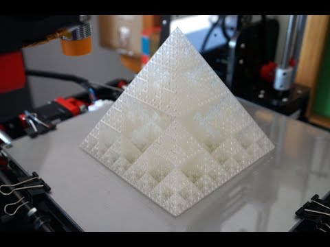
After some calibration, good cube samples were printed with dimensions of 1x1x1 cm. As a result, there is a significant displacement of the layers.
So I recommend setting the A4988 to 1/16 microstepping and adjusting the current to the minimum value.
You can also play around with the Arduino firmware to get better results.
Leave your comments, questions and share your personal experience below. In the discussion, new ideas and projects are often born!
Why the first 3D printer is worth assembling yourself / Sudo Null IT News
- 0207
- It's faster than waiting from China Anet A8 for $109
- This is better (with non-crooked hands)
And finally, sooner or later you will face the need to repair / modify the printer and you will still have to master the practical skills of these devices.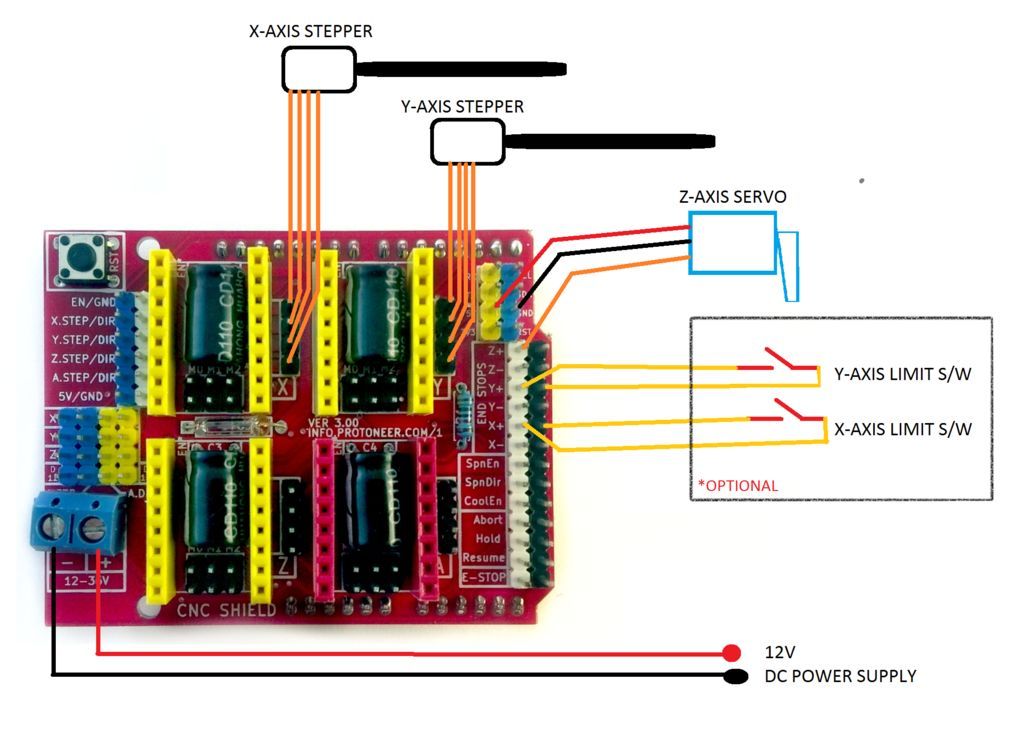
And at the most inopportune moment.
And given that there were New Year holidays ahead and a long quarantine winter evenings,
I bought all the necessary components in two days in three local stores, which cost the same $ 109.
And only thanks to the "Martian rule" the total amount increased by only three evergreens.
But contrary to the well-known tape from the film, I used blue (and how could I do without it) electrical tape and plastic ties.
In general, if you are only thinking of assembling a 3D printer - welcome under cat,
where will be my thoughts on the design and assembly of some nodes.
For there are so many detailed assembly instructions on the Internet.
So, let's start with the Martian rule - after purchasing all the necessary components, consider that you are on the red planet, and the next rocket from Earth will be in half a year.
Thanks to this, I avoided an increase in the cost of the device by at least one and a half times and still improved the quality of the mechanical part.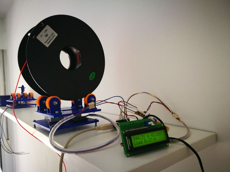
The only thing you can afford is to go to neighboring manufactured goods or unscrew a spare part from your favorite rover is large.
Next, we will talk about assembling a Prusa-compatible Graber I3 printer, but it also applies to any device based on the RAMPS 1.4 + Arduino Mega 2560 control board. his hand and began to shake.
Correct! Without proper mechanical strength, you will either have to set the level of the printer table every time, or screw it with screws to the kitchen worktop.
From this point of view, the presence of a high box at the base adds rigidity compared to the original grabber or Annushka.
But the second time from the start I would have already assembled RepRap Mendel
Yes, the body is made of plywood, as I will have to paint, peel and drill during assembly, the main thing is not to loosen the seats giving room for backlash.
It is better to paint with acrylic varnishes - they do not stink, unless their version is sprayed.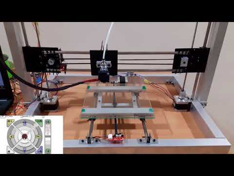
And of course, plywood is preferable to metal in terms of acoustic comfort.
The only disadvantage of the selected ATX version of the case is the inconvenient vertical position of the screen compared to the original Graber version:
Pluses - better durability, you don't have to bother with laying wires and fixing the control board, the use of cheap ATX power supplies.
So we come to the second cornerstone issue - NUTRITION.
Our 12 volt unit should provide 20A.
Remember how you chose a PSU for your gaming/school/work PC?
By weight!
I will say right away that if you buy a new power supply from a store, it is no lighter than 1 kilo and the declared power is from 400W.
If used - look at the current and before use you should remove the cover and blow out all the dust with a compressor - at a tire fitting you will blow it out for three rubles along with cockroaches.
Go ahead, computer scientists / 3D-shniks are cool guys, but sometimes they forget Ohm's law by connecting power to the RAMPS with one, Carl wire AWG-20 (section ~ 0. 5mm sq.)
I did the right thing and made a mistake!!!
On a hot table with a power of 120W, a current of 10A simply melted the power connector
I had to dismantle it and solder the wires.
Yes, about soldering irons - the power of 60W is decidedly small: neither the old-fashioned one with a copper (thick) tip, nor the modern one with a thermostat could melt the solder in the process of soldering an acoustic wire with a cross section of 1.5 squares to a hot table.
I had to unearth an ax from the pantry:
But it will not be a crime to use a wire of 1 square and solder not 3, but 2 twisted AWG-20 wires from the power supply, then 60W is enough.
Continuing the topic of Ohm's law - You have already purchased "cheap" NEMA-17 stepper motors, it's time to look at the current consumption of the windings.
Standard model 1.66 (1.7) A, reinforced - 2 (2.1) A, "quiet / cheap" - 1.33 A, I have the last one.
The current produced by a conventional driver 4988 is up to 2Amps (even the dock does not speak to the winding or in general.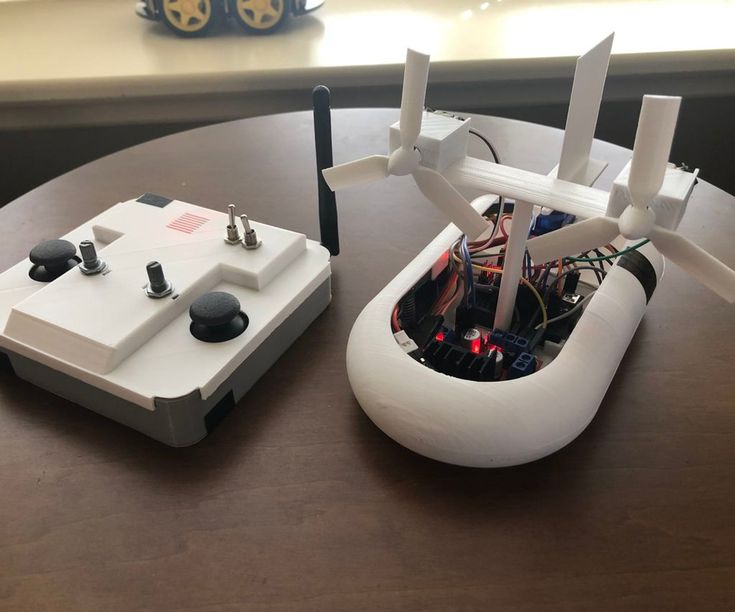
Everything seems OK, but there are two motors and RAMPS on the Z axis, and other control boards obviously contain two connectors for their parallel connection.
No, it's not scary if the R100 resistors are charred at the maximum current (there are boards with R50 for half the current).
And not even that the engines do not receive enough power (I have 0.75A everywhere except for the Z axis)
It's just that with this inclusion, the characteristics of the engines must match ABSOLUTELY, otherwise a wedge / skipping steps is possible in certain modes.
The REPETIER firmware did not cope with this at all, MARLIN got lost once at the stage of moving the extruder from the parking position at the beginning of printing.
Neither shuffling the motors nor the drivers helped.
The Z axis with two motors is saved only by their serial connection:
And oh, miracle, everything worked not on 2 amperes, but on the same 0.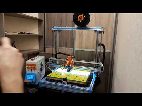 75 as the rest of the axes!
Someone may reproach me for the insufficient accuracy of the assembly of the axles, and as a result, the large required force on the Z-shafts.
I will answer - with the printer turned off, turn the right / left shaft by hand - what will happen to the free one?
That's right, for most it will remain motionless, but for me, when connected in parallel due to self-induction, the second shaft also spun.
Yes, about the shafts - usually, the Graber is designed for Hozmag threaded studs m5 with a pitch of 0.8mm.
They should be lubricated with any paste-like grease for bearings - CV joint, "blue" for needle bearings, graphite and hot grease!
In general, you are on your way to your grandfather's garage / car market, or even better, take lubricant from moon rover bike chain.
Of course, you can also buy the glamorous white Molycote-DX, but this is a matter of taste.
Yes, here the "Martian rule" saved me for the first time - I screwed up the sockets of the nuts of the left carriage of the Z axis Almost ran to buy 3D plastic X/Z carriages and "regular" trapezoidal studs/nuts But no, it turned out that you can throw away the extra / incorrect pads, and nuts on m6 are perfectly clamped between the elements of the plywood carriage: By the way, there were no stainless steel studs in the local hardware store - I took ordinary, galvanized ones. Filed off the threads a bit so they fit into 5mm sockets and bingo! The advantages of such tuning are a normally considered thread pitch of 1mm and the fact that not a threaded part, but a cylindrical part is clamped into the stepper sleeve! Yes, I recommend reaming the mounting holes of the Z-axis motors with a 5-bit drill before assembling - the distance between the guide and the threaded stud varies slightly in mounting and carriages! As a result, this leads to the fact that when moving along the Z axis, the upper ends of the pins move in a circular orbit, and the extruder shakes. In general, you need to select the position of the motors so that the pins remain on the same axis when the axes rotate (via the printer menu). In addition, many mounting holes were reamed, because the sockets in the plywood of my version of the printer are cut out for the M5 nut. Don't forget to press down on the plank when drilling from the back side, otherwise chipping of the plywood can be catastrophic. In a word, the base of the body is assembled on five-millimeter bolts!!! Yeah, and the notorious left carriage is generally assembled on screeds: The fact is that with 6mm studs and 4 fastening screws, a touch was found on their threaded parts. I didn't use 3mm screws and hope for half a millimeter, but used zip ties. This is a truly unique fastener that has replaced the wire used in the past. The only thing that screeds cannot withstand is water hammer in the country water supply. So if you're going to Mars, grab more zip ties! Now let's move on to the control board itself, or rather to the stepper motor drivers and their settings. Let's talk more specifically about the fight against noise. Someone puts expensive TMC2100 drivers in "silent" mode (by the way, you need only two of them - on the X and Y axes) But it's really all about psychoacoustics: And now let's calculate - with a microstep of 1/16, a carriage speed of 60 mm / s and a 20-tooth gear with a 2 mm belt pitch, we get a frequency of 4800 Hz !!! OMG! This is the same peak frequency of perception! Is it possible to double the microstepping (and at the same time the current in order to avoid skipping steps) by installing a DRV8825? thereby shifting the frequency range upwards. And you can show the noise of the middle finger Of course, you can completely remove the microsteps, and stop at the positioning accuracy of the X, Y axes of 0.2 mm. For most tasks, this is enough, the printer will start to "bass" at 300Hz. But it's all about individual preference and sound perception - experiment with a smaller microstep divider and find your comfortable frequency! Where the DRV8825 really comes in handy at 1/32 micro pitch is the standard MK8 extruder! If we calculate that with a 1.75mm filament and an 11mm toothed roller, on a standard 0.4mm nozzle and a 16 divider, we get a 0.2mm column of plastic per step!!! This replacement is justified only after adjusting the pressing force, extruder temperature, plastic type and stepper motor current! If you cannot ensure that the feed system operates normally without clicking and with less than half the nominal current on the stepper, this path is not suitable. Then you should either print a gear feed system or buy a "Titan", which will contradict the "Martian Rule". Has the quality improved from such tuning? At least the supports began to separate without excessive effort, which is already an indicator. To print gears and other parts of the RepRap system (partially self-reproducing printer), a certain print quality is required. But having reached it, the need for the above paragraph disappears. OK, the second most important part after assembly/adjustment of the X/Z axis is the print table!!! Here I am not against plywood, but not for it either! Maybe the proximity of the heating element, even if it was covered with thermal insulation, was influenced by the fact that I did not paint the plywood base with silver, or maybe three bearings instead of four. In general, the level of the table walked constantly, unpredictably and by 0. And if it weren't for the "Martian Rule", an auto level would have been bought. In a word, armed with a grinder, I built a table for 4 bearings from an aluminum-polyethylene-aluminum sandwich: Now the table walks no more than 0.05 mm (I checked it with probes to adjust the valves) and I don’t even correct it for the layer 0.20/0.30 mm. Yes, the springs are mega-rigid, I took brass adjusting screws from the same table as the upper support / spring guides. And the glass of the table, it is 4 mm, because this is its main rigid element (the 1.5 mm textolite of the heater "walks" and bends as it wants). Clamps should preferably be placed as close as possible to the corners, but this interferes with the control/adjustment of the gap! And yes, my axles turned out to be longer, I didn’t cut them, but fixed them with ties - it’s more reliable! Print area is 190x180x180 (XYZ). Of course, you can radically redo everything (make the table lower, change the fastening of the belt on it, otherwise position the extruder), but for now it suits me. And a few words about firmware - I counted 8 different names, but I tried only three: At first I grabbed the second version of Marlin, hoping to switch from Arduino Mega to Due, which has been gathering dust in the box for a long time, but the firmware is heavy both during compilation and for the 8-bit Atmega2560. Then stuck with engines in Repetir. Teacup considered between glasses of tea - not ours how to quickly launch the 2004 screen - gave up this idea. Well, I returned to Marlin version 1.1.9, downloading separately examples of firmware from github. I came up with a fresh version from Aliexpress's Prusa_i3_MKS_Gen_2Z_V1.2, set only my table sizes, steps and inverted the Y direction. That's basically all my notes/remarks. Yes, the choice of filament should also be taken responsibly. Don't print out of shit Liberator! Of course, you've probably already bought a roll of ABS along with the rest of the accessories, but it's better to save it for later, and take PETj, coPET or PLA first. I bought coPET right away. The fact is that these plastics are not as demanding in terms of parameters and printing conditions as ABS. Someone even prints with them on printers without heated bed! ABS is good only for the price, but if you print in a living room not under an exhaust hood, the aroma will still be the same. Yes, and they talk about the dangers to health from its fumes, and heating the table to the desired 100-110 degrees Celsius requires titanic patience. By the way, I got the "Zaporozhets" right, up to a hundred So, having printed a skein of filament, I almost ordered a second one, but I found ABS + half the price! On it, the part behaves differently (compared to conventional ABS), the temperature of the table is 90-100 degrees Celsius, and even the first model was still printed, albeit with a tear off of the edges. After that, a hood with a carbon filter was built, a new coil holder and blowing the RAMPS power transistors. And even the edges of the parts began to stick better. It would seem that ABS + is an absolute plus, but no! On the third model, the edges of the part rose along with the 4mm glass, which predictably burst in the middle!!! Maybe the fault was a glass defect, but somehow I didn’t want to check it. Therefore, my choice is PET-plastics (PETj, coPET and others like them) - the table can not be heated at all (when using a regular PVP-based glue stick). I heat it for the first layer to 75 degrees Celsius, then - 70 in order to avoid peeling high parts.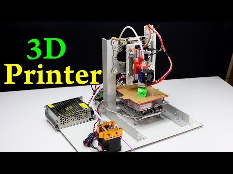

jumper by moving to a 1/4 microstep. 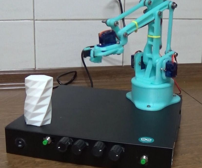
 2 mm!
2 mm! 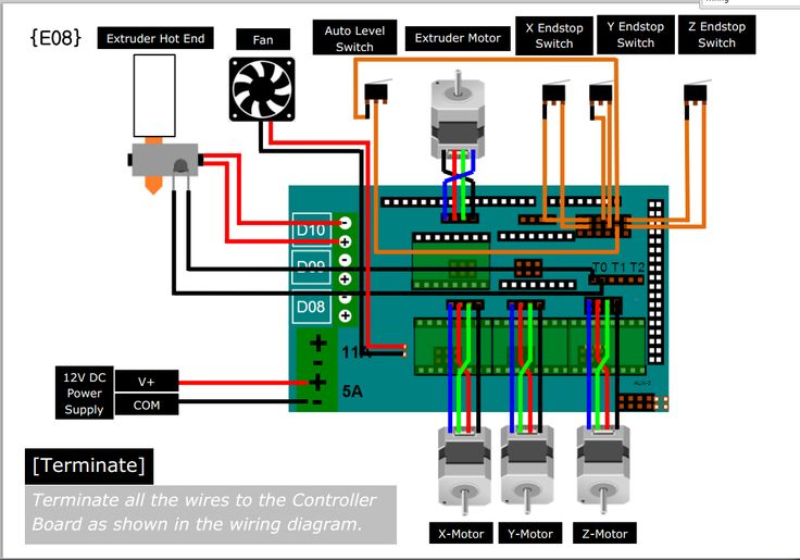
accelerates heats for 10 minutes, up to 120 - nothing.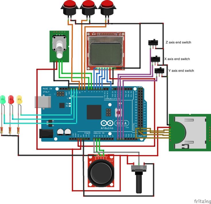
Learn more