3D printing antenna
How To 3D Print Your Own Working Antennas
It Works, and You Can Do It!
What RF engineer has not thought about 3D printing an antenna? It’s a natural combination of RF curiosity and and basic 3D printing capabilities. You have probably even seen social media photos and posts about this achievement. But do these antennas work? Has anyone properly tested them? Is it even practical with simple materials and processes?
Download files for all 8 antennas: STL files are in THIS zipped archive, and SketchUp files are in THIS zipped archive (created with the free Sketchup Make 2017).
3D Printing a Horn AntennaSo we decided to give it a try ourselves, and also to add some value to the conversation. We are a professional antenna testing service with an RF anechoic chamber. We can build, optimize, and fully evaluate 3D antenna prints to answer these fundamental questions. In the end, it turned out to be quite practical, but not without a trashcan full or horns and lots of trial and error.
In the spirit of true science, we wanted to create plastic horns that could be tested against their commercial all-metal counterparts. So we chose to 3D print, metalize, and test the family of 15 dBi standard gain horns. Their simple rectangular horn shape design is decades old, and their standard geometries have very predictable gain. These “waveguide” horns have readily available coax launches (adapters) easily found surplus, purchased new, or even 3D printed. Despite their simplicity, commercial standard gain horns are expensive, normally priced from $500 to $1500. Contrast this to a spray metalized 3D print costing a dollar!
We limited our scope to the 2-40 GHz frequency range. This will entirely encompass the practical limits of common 3D filament printing. In the S Band (2-4 GHz), the standard gain 15 dBi horn is the size of a salad bowl, and required our large format printer. It could also be printed in parts and glued together from smaller prints. In the Ka band (26-40 GHz) the same 15 dBi horn will fit into the palm of your hand, and would challenge the tolerances of most typical 3D printers. Above 40 GHz, test equipment gets very expensive and parts get impractically small for casual experimenters.
Metalization
We chose MG Chemicals’ shielding spray paints for metalization because they are easy to buy (even on Amazon) and simple to use. Our first test antenna was an X band horn (8-12 GHz) with an easy to print 4 inch aperture. Two copies were printed to evaluate two common paints: “841 Super Shield™ Nickel” and “843AR Super Shield™ Silver Coated Copper”. Each was given two spray coats with drying time in between.
Disappointment !
The spec sheets for both paints showed impressive surface conductivity numbers and the metalized horns simply looked great! You can see the gain results in the horn shown in the left of Figure 3. We had high expectations. However, when patterned in the anechoic chamber, the results were terrible. Forward gain was only about 5 dBi, as opposed to the expected 15 dBi. But examining the test results showed that something was actually working. Both antennas had directivity of about 15 dB and the expected 30 degree beamwidths. Since return loss was “great” (> 20 dB), the only explanation was that the metalization’s realized surface conductivity was poor, causing the horns to suffer about 10 dB of internal loss.
Pre-Testing with VSWR
We devised a simple bench test to prove out this theory and to “pre test” antennas for this kind of loss. You should utilize this very useful approach, since not everyone has their own free-space antenna testing lab. Measuring the return loss (VSWR) of an antenna is the most common performance test (and does not require an anechoic chamber). The rule of thumb is that high return losses of more than 10 dB point to a “good” antenna. The thinking is that 90% or more of transmitted energy sent to the “good” antenna will radiate because it does not reflect back to the source. This is normally a useful test, when you can assume your antenna has small or zero losses. However a lossy antenna, or even a “dummy load” also has great return loss too!
Consider the low return loss from a short circuit. If you short a coaxial cable or the aperture of a low loss metal horn antenna, you can also expect a low return loss (large reflection). We verified these low return losses on “shorted” lab grade commercial horn antennas by covering their apertures with aluminum cooking foil. The same shorted aperture test on the 3D printed horns showed large (> 20 dB) return losses, indicating they were better attenuators than antennas!
In the figure below you can see that the “smoothed” surface antenna showed the desired low return losses. While there is some ripple due to the imperfect cooking foil “short” on the horn, the important thing to look for is some frequencies of low (approximately 1 dB) return loss. This could not happen if the inside surface of the antenna were lossy.
VSWR Return Loss of Shorted Aperture 3D Printed Horn AntennasLeft: Raw Print, Right: Solvent SmoothedDespite the shiny appearance of the metalized paint, and the near-zero ohm meter resistance readings, surface resistance was the only possible loss mechanism. The tiny surface ripple artifacts of the 3D printing layers are small compared to the relatively large operating wavelength (1 inch at X Band). However, surface smoothing did eventually prove to be the key to removing this loss and achieving the target 15 dBi gain across the whole 2-40 GHz test range. But even applying multiple “liberal” coats of conductive paint did not sufficiently lower this loss without prior smoothing.
Surface Preparation
Sanding is an obvious way to smooth the 3D layer surface roughness. It works well, but it is time consuming. The horn’s funnel shape also creates triangular facets that are enclosed and tapered making power sanding tools impractical. After experimentation, we found that “solvent smoothing” was the most time effective and least effort. Acetone is a well known and useful solvent for ABS plastic prints, and it worked nicely on prints from our smaller ABS filament printer. Our large format printer only uses PLA filament, which did not seem to have a readily available solvent. However, a little research uncovered dichloromethane (methylene chloride) and a gallon was purchased on Amazon. It was highly effective at softening and smoothing the surface roughness on PLA plastic.
Chemical Safety
Both solvents are hazardous, but dichloromethane is especially poisonous. It has historically been the key ingredient in common paint stripper, but is being phased out due to its toxicity when used for DIY home projects. After some trial and error, we found the following process worked well. The resulting smoothed surface is shown in the right of the figure above.
Always Work Outside and Wear ProtectionWork outdoors, since “adequate ventilation” is NOT practical indoors. You will still need a respirator mask that is rated for organic solvents (commonly available for “oil” based painting). Use full length chemical gloves that are specifically rated for your solvent, and protect these delicate chemical gloves by also wearing “work gloves” over top of them. You must also wear eye protection, since you WILL be splashing and brushing solvent.
Solvent Smoothing
Solvent Smoothing OutdoorsWe found it convenient to pour solvent into a common metal paint-roller tray and use this to brush on, scrub, and re-catch the solvent as in this figure. Disposable bristle brushes are best along with metal kitchen pot scrubbing pads. Don’t use plastic brushes or the green/blue plastic kitchen scrub pads, since the dichloromethane will soften them. It takes only a minute to smooth the inside of even the largest horn with the pot scrubber (or steel wool) if it is kept wet with solvent. A round bottle brush also easily scrubbed the waveguide portion of the horn. There is no need to smooth or metalize the outside of the horn, just work the inside surfaces and mating flange.
If you are assembling a larger antenna from smaller prints, now is the perfect time to “solvent weld” the already softened parts. Press and hold them together for about a minute while the solvent evaporates.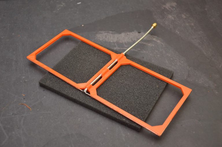
Applying the conductive spray paint is straightforward, proceed as you would spray paint any object. It is best done outdoors too, holding it in one hand with a glove allowing easy reorientation to get at all inside surfaces and the flange. Excess paint is simply shaken off. Two coats were always used and worked well.
Epoxy Coating (Painting)
Conductive paint gaps on unsanded epoxyThere is a second practical option available for surface smoothing. You can cover the rough 3D printed surface with a paint-on two-part epoxy coating. We tried “XTC-3D” from smooth-on.com, and it worked well for prints from 2 to 18 GHz. Some optional quick pre-sanding before application removes “large” high spots from rough surfaces. However, post sanding is not optional. The cured shiny surface looks great, but will not accept the metalized paint until lightly sanded. While less work than sanding smooth a rough 3D print, you will not be able to avoid this step.![]() Any unsanded sections of “shiny” epoxy will not accept the metalization paint. We found inside corners to be problematic. In this photo, you can see blue plastic peeking through the conductive paint where the epoxy was not completely sanded. In horns from 18 to 40 GHz, the wave-guide features were just too small for the relatively thick coating. Critical dimensions were distorted, and holes and inside radiuses were starting to get filled in. However, antennas are quite tiny at these frequencies and you can smooth them quickly with small hobby files. There is really no need for solvent or epoxy coatings for antenans this small.
Any unsanded sections of “shiny” epoxy will not accept the metalization paint. We found inside corners to be problematic. In this photo, you can see blue plastic peeking through the conductive paint where the epoxy was not completely sanded. In horns from 18 to 40 GHz, the wave-guide features were just too small for the relatively thick coating. Critical dimensions were distorted, and holes and inside radiuses were starting to get filled in. However, antennas are quite tiny at these frequencies and you can smooth them quickly with small hobby files. There is really no need for solvent or epoxy coatings for antenans this small.
Metalized Coating Choices
The nickel version of the paint seemed to have several dB of loss at all frequencies despite surface smoothing. The chart below shows the nickel paint’s “performance hit” (surface loss) even in the S-band.
Detailed Gain Comparison Commercial All-Metal vs. Plastic 3D Printed Horn Antennas3D Printed K-Band Horn Antenna in Anechoic Chamber
Luckily, the silver/copper version spray shielding paint worked well up to 26 GHz. But from 26 to 40 GHz the tiny Ka horn still displayed about 3 dB loss by having only 12 dBi of gain (even when solvent smoothed). This was easily solved by sanding the horn completely smooth with a tiny file, and repainting it. Since this Ka band horn is only an inch in size, its soft plastic walls were trivial to file smooth in just a minute. This extra smoothing step allowed it to display very low shorted aperture return loss on the bench and fully restored its expected 15 dBi gain in the chamber, as pictured above.
Conclusions
Yes, you can 3D print your own working microwave antennas using common materials and your “home-brewing” skills. Just smooth the active surfaces with solvent, sanding, epoxy, or filing then use our recommended conductive paint. If you can check the shorted aperture return loss / VSWR and verify that it has at least some frequencies of low return loss (less than 1 dB), you can reasonably expect the same antenna performance as a solid metal antenna. Complex shapes can be accommodated by splitting 3D prints into sections that allow for sanding/smoothing access before assembly by gluing or solvent welding. You can make various “cavity” electromagnetic parts like wave guides or coax-adapters this way. The conductive spray paint easily flows over and obscures surface sanding scratches and seams.
Results
The graph above shows how good these horns can be. It compares a lab grade Waveline Model 299 Standard Gain Horn Antenna (15 dBi S Band model) and two 3D printed exact copies. The plastic versions were printed in PLA, solvent smoothed, and spray painted as described here. All three antennas were tested using the same Waveline Model 201NF Coax Adapter. The copper/silver painted 3D printed antenna’s gain was only +/- 0.2 dB different from the commercial horn antenna, well within measurement repeatability. The third curve on this graph shows the other identical printed antenna with two coats of the nickel based conductive coating. This formulation displays about 0.5 dB less gain, and gets worse by up to 5 dB at 10 GHz. The graph below shows the measured gain of our entire family of 15 dBi horns from 2 to 40 GHz, all hitting their gain targets.
If you would like to experiment further, we have made the STL printable files available for download. All 3D designs were done with “SketchUp Make 2017”, a free 3D CAD design tool. The SketchUp files for these horns are also downloadable here if you would like to edit the geometries. Links are below …
Download the SketchUp 3D-model files here
Download the 3D printable STL files here
An Overview of 3D Printed Antennas for 5G Communications and Beyond
Henry Giddens, and Yang Hao, Queen Mary University of London
IEEE Future Networks Tech Focus, Volume 4, Issue 1, November 2020
Abstract
5G communication systems will once again revolutionize the ways that people connect and communicate with each other. Future mobile networks will also span new frequency bands in mm-wave and THz bands. The combination of the need to wirelessly connect everyday consumer devices to the internet, and the range of new frequency bands on offer, has necessitated research into new antenna systems. One technology that is enabling the realization of a new class of antennas is 3D printing. This has been fueled in part by the rise of new antenna design techniques such as transformation optics and topological optimization, whilst further developments in new filament materials designed specifically for electromagnetic applications means complex antenna geometries can now be easily realized. This article presents an overview of the ways in which additive manufacturing is enabling the development of novel antennas for 5G wireless networks and beyond.
1. Introduction
The 5th generation of mobile communications will once again offer vast improvements in bandwidth and coverage, which will translate into a user experience of fast download speeds and an uninterrupted connection to the network. The antennas used in these networks will need to facilitate these features whilst maintaining low profile and conformal physical dimensions so that they can be included in consumer devices and access points. At the mm-wave bands, directive communications is essential to overcome the higher path loss and steerable beams will be required to communicate with mobile targets. Future communication networks will look to utilize even high frequencies, approaching the THz bands and sub-millimeter wavelengths. Antennas will also have to support wide input-impedance bandwidths, whilst maintaining good radiation efficiency and reliable radiation patterns. In this article we look at how 3D printing is addressing these issues. The rapid rise and falling cost of 3D printing technology over the last 10 years has generated a growing industry estimated to be worth over $10 billion in 2020 [1]. In technology-focusses industries this has manifested itself in small-scale manufacturing and rapid prototyping of new de- vices.
 In recent years, antenna research has taken advantage of the possibilities offered by additive manufacturing techniques. For example, antennas with complex spacial material profiles can now be realized with various 3D printing techniques. Furthermore, new design techniques for conformal antennas such as transformation optics and multi-objective topological optimization are being utilized which are particularly suited to generating printable antennas [2], [3]. Metallic printing has allowed engineers to manufacture new types of antennas up to THz frequencies, whilst 3D printing has also contributed to the realization of microwave metamaterial antennas.
2. Materials and Printing Techniques
A number of 3D printing techniques have been used for printing antenna and electromagnetic structures. These include fused deposition modeling (FDM), also known as fused filament fabrication (FFF), Polyjet printing, stereo lithography (SLA), micro-SLA and photonic polymerization. Each method has advantages and trade-offs which are suited to manufacturing different types of antennas. For example, FDM, where filament materials are extruded from a heated nozzle, is generally the cheapest 3D printing technique available, whilst it also benefits from a wide variety of filaments and can print with multiple materials in a single print. The SLA and polymerization techniques use laser or UV light to cure resin materials into the desired 3D shape. As a result, they can achieve a much higher resolution when compared to FDM, down to the 10s of nanometers scale. They are better suited to fabrication of smaller structures, and therefore are used to fabricate antennas operating in mm-wave and THz frequency bands. The materials used in these printers are essentially a light curable resin, and subsequently cannot be modified to the extent that FDM filaments have been.
3D printing has most commonly been used for manufacturing dielectric-based antennas. This is due to the fact that printing dielectric materials is far easier than printing conductive filaments. Dielectric materials can be printed using fused deposition modeling (FDM) 3D printers that can be purchased for just a few hundred dollars, whilst standard filament materials such as ABS (Acrylonitrile butadiene styrene, a common thermoplastic) and PLA (polylactic acid, a biodegradable thermoplastic polyester) have been shown to have low dielectric losses up to 100s of GHz [4]. Furthermore, specialized dielectric filaments are available for electromagnetic (EM) applications with tailored dielectric constants up to a value of 12 [5]. Fig. 1 shows the measured dielectric properties of a selection of Preperm filaments for two mm- wave frequency bands, 70-110 GHz and 220-320 GHz. All filaments are stable with frequency and the losses only become significant for the highest permittivity materials when the frequency exceeds 200 GHz.
Figure 1. Measured relative permittivity and loss tangent of electromagnetic dielectric filaments available from PREPERM [5] at mm-wave frequencies. The filaments were printed using a Prusa i3 MK3s 3D printer into 20 x 20 mm samples with 100% fill factor and measured using a quasi-optical transmissometer. The shaded area shows the error boundary associated with the measured data.
Antennas with gradient-index material profiles (i.e. materials that have spatially varying dielectric properties) are uniquely suited to 3D printing for a number of reasons. From the effective-medium theory it is possible to predict the effective permittivity of a volume of material where only a percentage of that volume is filled with a dielectric filament, and the rest of the volume by air. 3D printed dielectric metamaterials can easily be printed to obtain precise effective permittivity, and this can be further varied throughout the total volume of the antenna to obtain graded-index materials so long as the unit cell dimensions are significantly smaller than the wavelength. Multi-material 3D printing can be used to extend both the range and steepness of the dielectric gradient which opens up new possibilities in the antenna design [6].![]()
3. Dielectric Antennas
Due to the ease of printing dielectrics compared to conductive materials, 3D printing is best suited to fabricating dielectric antennas such as lenses and DRAs. Lens have been demonstrated using almost all the common 3D printing methodologies spanning a wide range of frequencies from microwaves through the mm-wave bands and up to THz. Lens antennas are particularly suited to mm-wave 5G frequency bands as they generate directive radiation, are not physically large due to the small wavelength, and can also have beam steerable capabilities, whilst the wavelength is not so small as to be beyond the resolution of FDM 3D printers. The Luneburg lens for example, is a multi-focal lens able to concentrate a plane wave impeding on any surface to a point on the opposite surface of the lens, requires a material profile with permittivity of 2 in the center and 1 on the surface [7], as shown in Fig. 2 (a - c). Whilst the Luneburg lens has been known to optical engineers since it was proposed by Rudolf Luneburg in 1944, 3D printing has offered a simple solution for easy fabrication. In order to adapt the Luneburg lens and make it more practical for real-world applications, various geometrical modifications to the Luneburg lens have been demonstrated through trans- formation optics coordinate transformations. These include the Gutman lens Fig. 2 (d-f) [8], the compressed Luneburg lens Fig. 2 (g - j) [9], and the flat Luneburg lens [10]. Each of these modifications requires a more complex material profile, however they can be realized using the 3D printing techniques previously described. Each modification to the Luneburg lens importantly retains the key feature of generating directive, steerable beams which are necessary for 5G mm-wave and future THz communication links. Fig. 2 shows some examples of the various Luneburg Lenses which have been 3D printed for mmWave beam scanning applications. The lenses are often excited using traditional antenna elements such as patches, waveguide probes and horns, with the lens taking the role of shaping and steering the antenna beam.
Lens antennas at THz frequencies will form a key element in THz communication systems as they are wideband devices and generate the directive beams necessitated by the small wavelength and high path loss. 3D printed THz lenses have been demonstrated through micro SLA 3D printing, which are able to print with sub-micron resolution [11] that is require to generate graded-index interfaces at THz wavelengths. A number of diffractive lenses operating at 0.625 THz were demonstrated in [12] using low cost 3D printing techniques.
3D printing has also been use to realize antennas in specialist radios where customized designs are required. For example, an 8-beam lens operating in military mobile-adhoc networks with multi-functionality and 360° coverage was presented in [6]. The lens, shown in Fig. 3, is able to radiate with an optimized 45° beamwidth in each of its 8 sectors, but can switch to multi-beam mode covering 8 directions in any one instance due to the symmetry of the lens. The lens was 3D printed using multi-material printing with a permittivity gradient ranging from 3. 6 on the edge to 1 in the center, and takes a conformal octagonal shape.
Dielectric resonator antennas offer unique advantages over traditional antennas, such as a reduced size whilst maintaining a wide input impedance bandwidth and good radiation efficiency, which can be beneficial to 5G communications networks. 3D printing has also opened up new possibilities in dielectric resonator antenna research. For example, the gradient-index DRA presented in [13] and shown in Fig. 4 excites three transverse modes which are merged together to provide a wide input impedance bandwidth from 4 - 8 GHz. 3D printed DRA arrays have also been demonstrated as high- gain access point antennas [14], and the technology has been further applied to mm-wave frequencies [15].
Figure 2. An overview of beam steerable 3D printed lens antennas for mmWave communications. (a) - Permittivity distribution of a classic Luneburg lens antenna [7]. (b) - Photograph of 3D printed Luneburg Lens antenna using effective medium theory. (c) - Measured radiation patterns at 28 GHz with feed position at 0◦, 90◦, -90◦, and 180◦. (d) - Permittivity distribution of the Gutman lens with the focal point moved to a position of 0.45R [8]. (e) Photograph of the 3D printed Gutman lens at 60 GHz. (f) - Simulated electric field patterns showing beam steering as the feed position is moved along the flat face of the lens. (g) - Permittivity distribution of a compressed Luneburg lens [9]. (h) - photograph of the 3D printed compressed Luneburg lens at 84 GHz. (i) - Setup for multi-material 3D printing of the compressed lens with 5 different filaments. (j) - Measured radiation patterns of the compressed lens at 84 GHz. All measurements and fabrication of lens antennas performed at Queen Mary University London.
Figure 3. 3D-printed 8-beam dielectric lens antenna with multi-functionality including optimized 45° radiation pattern [6].
Figure 4. A graded-index 3D-printed dielectric resonator antennas with 3 transverse modes and wide input impedance bandwidth [13].
4. Metallic Antennas
Most traditional antenna structures require a conductive element in order to interface with the input port and provide resonance. 3D printing conductive materials for electromagnetic applications remains a challenging problem for a number of reasons. Poor conductors, which are acceptable for 3D printed electronic circuits, are not suited to antenna applications as the losses severely impact radiation efficiencies. However, conductive filaments have recently become commercially available which may offer some potential, such as the Multi3D Electrificonductive filament with a quoted volume resistivity of 0.006 Ω cm [16]. For purely metallic antennas, specialist metal 3D printers are an alternative option. These can directly print the metallic materials including aluminum, steel, titanium and cobalt through direct metal laser sintering (DMLS). For example, Jun et. al. 3D printed fractal monopole antennas (Fig. 5) using metal AM which have ultra-wideband radiation characteristics and geometries that would be difficult to realize using subtractive manufacturing methods [17].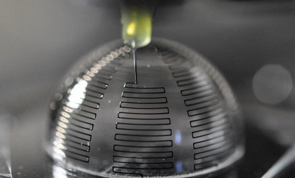 Metallic printing has also been used to fabricate horn antennas and waveguides at 110-170 GHz [18], although surface roughness and layer height can become an issue at submillimeter wavelengths. Metallic printing is likely to be widely utilized to fabricate mmWave and THz antennas that required intricate 3D geometries that traditional techniques are incapable of achieving.
Figure 5. Fractal monopole antenna using metallic AM technology [17].
An alternative and cost effective approach for 3D printing metallized antenna parts is to print using a regular filament or resins, and then coat the parts in conductive materials [19–22]. This allows the intricate and detailed 3D shapes associated with additive manufacturing techniques to be incorporated into antenna technologies, has a much lower material cost than pure metal antennas, and has other advantages in terms of weight [21]. 4 different coating techniques, Jet Metal Processing (JMT), aerosol spray coating using copper and nickel conductive paints, and brush painting with electrolube silver conductive paint, were analyzed in [20]. JMT is able to achieve performance comparable to PEC antennas at both 10 GHz and 30 GHz. Metal-coated 3D printed parabolic mirrors have also been demonstrated with nanometer scale surface roughness for THz applications [22]. Low cost metallization techniques clearly offer possibilities for mass production of low cost 3D printed antennas for 5G, mm-wave and THz communications.
5. Metamaterials
Metamaterials are artificially designed periodic structures which can be designed to have properties which are not found in naturally occurring materials. Electromagnetic metamate- rials have been demonstrated with negative refractive index components for applications such as cloaking. Metamaterials can also be utilized in more practical applications including wireless communication. 3D printing is a valuable tool for further innovation in this field, as it allows multiple materials to be combined in complex structures that will give an optimal material response. For example, a chequerboard dielectric metamaterial with anisotropic properties was 3D printed in [23] using two high-contrast dielectric filaments. The authors in [24] 3D printed a broadband microwave metamaterial with customized permittivity and permeability using the electrificonductive filament.
6. Summary
In summary, it is clear that 3D printing has already had a significant impact on antenna related research and development. With incoming 5G networks and trends for future communications systems moving to higher frequencies, additive manufacturing technology will become increasingly important to the industry. It is expected that widely available and low cost 3D printing techniques, such as FDM and SLA, as well as the more specialist additive manufacturing methods, including Nano-scale photonic printers and metallic 3D printing, will all contribute to the continued development and manufacture of novel antennas for wireless networks.
References
- “Global 3D printing industry market size,” library Catalog: www.statista.com. [Online]. Available: https://www.statista.com/ statistics/315386/global-market-for-3d-printers/
- O.
 Quevedo-Teruel, W. Tang, R. C. Mitchell-Thomas, A. Dyke, H. Dyke, L. Zhang, S. Haq, and Y. Hao, “Transformation optics for antennas: why limit the bandwidth with metamaterials?” Scientific Reports, vol. 3, no. 1, p. 1903, May 2013.
 - T. Maruyama, K. Yamamori, and Y. Kuwahara, “Design of Multibeam Dielectric Lens Antennas by Multiobjective Optimization,” IEEE Trans- actions on Antennas and Propagation, vol. 57, no. 1, pp. 57–63, Jan. 2009.
- J. M. Felcio, C. A. Fernandes, and J. R. Costa, “Complex permittivity and anisotropy measurement of 3D-printed PLA at microwaves and millimeter-waves,” in 2016 22nd International Conference on Applied Electromagnetics and Communications (ICECOM), Sep. 2016, pp. 1–6.
- “3D Filaments for Quick Prototyping,” library Catalog: www.preperm.com. [Online]. Available: https://www.preperm.com/ webshop/product-category/3d-filaments/
- H. Giddens and Y. Hao, “Multi-Beam Graded Dielectric Lens Antenna from Multi-Material 3D Printing,” IEEE Transactions on Antennas and Propagation, pp.
 1–1, 2020.
 - R. K. Luneburg, Mathematical Theory of Optics. University of California Press, 1966, google-Books-ID: VIZAy68oFiMC.
- A. S. Gutman, “Modified Luneberg Lens,” Journal of Applied Physics, vol. 25, no. 7, pp. 855–859, Jul. 1954.
- A. Demetriadou and Y. Hao, “Slim Luneburg lens for antenna applica- tions,” Optics Express, vol. 19, no. 21, pp. 19 925–19 934, Oct. 2011.
- C. Mateo-Segura, A. Dyke, H. Dyke, S. Haq, and Y. Hao, “Flat Luneburg Lens via Transformation Optics for Directive Antenna Applications,” IEEE Transactions on Antennas and Propagation, vol. 62, no. 4, pp. 1945–1953, Apr. 2014.
- F. Zhou, W. Cao, B. Dong, T. Reissman, W. Zhang, and C. Sun, “Additive Manufacturing of a 3D Terahertz Gradient-Refractive Index Lens,” Advanced Optical Materials, vol. 4, no. 7, pp. 1034–1040, 2016.
- W. D. Furlan, V. Ferrando, J. A. Monsoriu, P. Zagrajek, E. Czerwiska, and M.
 Szustakowski, “3D printed diffractive terahertz lenses,” Optics Letters, vol. 41, no. 8, pp. 1748–1751, Apr. 2016.
 - Z.-X. Xia, K. W. Leung, and K. Lu, “3-D-Printed Wideband Multi-Ring Dielectric Resonator Antenna,” IEEE Antennas and Wireless Propaga- tion Letters, vol. 18, no. 10, pp. 2110–2114, 2019.
- A. A. Althuwayb, K. A. Abdalmalak, C. S. Lee, G. Santamara-Botello, L. E. Garca-Castillo, D. Segovia-Vargas, and L. E. Garca-Muoz, “3-D- Printed Dielectric Resonator Antenna Arrays Based on Standing-Wave Feeding Approach,” IEEE Antennas and Wireless Propagation Letters, vol. 18, no. 10, pp. 2180–2183, 2019.
- D. C. Lugo, R. A. Ramirez, J. Castro, J. Wang, and T. M. Weller, “3D printed multilayer mm-wave dielectric rod antenna with enhanced gain,” in 2017 IEEE International Symposium on Antennas and Propagation USNC/URSI National Radio Science Meeting, Jul. 2017, pp. 1247–1248, iSSN: 1947-1491.
- “Electrifi Conductive Filament.
 ” [Online]. Available: https://www. multi3dllc.com/product/electrifi/
 - S. Y. Jun, B. Sanz-Izquierdo, E. A. Parker, D. Bird, and A. McClelland, “Manufacturing Considerations in the 3-D Printing of Fractal Antennas,” IEEE Transactions on Components, Packaging and Manufacturing Tech- nology, vol. 7, no. 11, pp. 1891–1898, Nov. 2017.
- B. Zhang, Z. Zhan, Y. Cao, H. Gulan, P. Linnr, J. Sun, T. Zwick, and H. Zirath, “Metallic 3-D Printed Antennas for Millimeter- and Submillimeter Wave Applications,” IEEE Transactions on Terahertz Science and Technology, vol. 6, no. 4, pp. 592–600, Jul. 2016.
- S. Alkaraki, A. S. Andy, Y. Gao, K.-F. Tong, Z. Ying, R. Donnan, and C. Parini, “Compact and Low-Cost 3-D Printed Antennas Metalized Using Spray-Coating Technology for 5G mm-Wave Communication Systems,” IEEE Antennas and Wireless Propagation Letters, vol. 17, no. 11, pp. 2051–2055, 2018.
- S. Alkaraki, Y. Gao, M. O. Munoz Torrico, S.
 Stremsdoerfer, E. Gayets, and C. Parini, “Performance Comparison of Simple and Low Cost Metallization Techniques for 3D Printed Antennas at 10 GHz and 30 GHz,” IEEE Access, vol. 6, pp. 64 261–64 269, 2018.
 - D. Shamvedi, O. J. McCarthy, E. O’Donoghue, P. O’Leary, and R. Raghavendra, “Improving the Strength-to-Weight Ratio of 3-D Printed Antennas: Metal Versus Polymer,” IEEE Antennas and Wireless Propagation Letters, vol. 17, no. 11, pp. 2065–2069, 2018.
- N. Vaidya and O. Solgaard, “3D printed optics with nanometer scale surface roughness,” Microsystems & Nanoengineering, vol. 4, no. 1, pp. 1–8, Jul. 2018.
- D. V. Isakov, Q. Lei, F. Castles, C. J. Stevens, C. R. M. Grovenor, and P. S. Grant, “3D printed anisotropic dielectric composite with meta- material features,” Materials & Design, vol. 93, pp. 423–430, Mar. 2016.
- Y. Xie, S. Ye, C. Reyes, P. Sithikong, B.-I. Popa, B. J. Wiley, and S.
 A. Cummer, “Microwave metamaterials made by fused deposition 3D printing of a highly conductive copper-based filament,” Applied Physics Letters, vol. 110, no. 18, p. 181903, May 2017.
Biography
Yang Hao is a Professor of Antennas and Electromagnetics at Queen Mary University of London. He also serves in the management team of Cambridge Graphene Centre since 2013. He is active in a number of areas, including computational electromagnetics, microwave metamaterials and transformation optics, antennas and radio propagation for body centric wireless networks, active antennas for millimeter/sub-millimeter applications and photonic integrated antennas. He co-published two books: “Antennas and Radio Propagation for Body-Centric Wireless Communications”, and “FDTD modelling of Metamaterials: Theory and Applications”. He has published more than 200 journal papers and is a frequent keynote speaker for many conferences. Prof. Hao was the Editor-in-Chief for the IEEE ANTENNAS AND WIRELESS PROPAGATION LETTERS. He founded a new open access journal and is now the Editor-in-Chief of EPJ Applied Metamaterials.
He won 2015 IET AF Harvey Research Prize and is a co-recipient of BAE Chairman’s Silver Award in 2014 and the Royal Society Wolfson Research Merit Award. Prof. Hao is an elected Fellow of Royal Academy of Engineering, IEEE and IET.
Professor Yang Hao received the Ph.D. degree from the Centre for Communications Research (CCR) at the University of Bristol, U.K. in 1998. From 1998 to 2000, he was a postdoc research fellow at the School of Electrical and Electronic Engineering, University of Birmingham, U.K.
Pageviews: 5754
Subscribe to Tech Focus
Join our IEEE Future Networks Technical Community and receive IEEE Future NetworksTech Focus delivered to your email.
Subscribe Now
Article Contributions Welcome
CALL FOR CONTRIBUTIONS
Submit Manuscript
Submit Manuscript via Track ChairAuthor guidelines can be found here.
Other Future Networks Publications
Archived Issues
Contact Us
IEEE Future Networks Tech Focus Editorial Board
Rod Waterhouse, Editor-in-Chief
Mithun Mukherjee, Managing Editor
Imran Shafique Ansari
Anwer Al-Dulaimi
Stefano Buzzi
Yunlong Cai
Zhi Ning Chen
Panagiotis Demestichas
Ashutosh Dutta
Yang Hao
Gerry Hayes
Chih-Lin I
James Irvine
Meng Lu
Amine Maaref
Thas Nirmalathas
Sen Wang
Shugong Xu
Haijun Zhang
How we printed the antenna
Development of technology and prototype production of a broadband logarithmic microwave antenna using additive technologies (3D printing)
From the beginning, very briefly about who we are and what prompted us to start the topic of this publication.
We are a small engineering team with considerable experience in the development of passive radar systems, as well as looking for and finding areas for ourselves to apply and develop our skills. In general, we try not to stand still, but to invent and do.
More about the antenna. One day, during an impromptu brainstorming session, the idea came up to 3D print a broadband antenna. There is only one goal - to obtain technology, thanks to which it will be possible to manufacture antennas with very similar radio technical characteristics. With traditional manufacturing methods, the spread of antenna characteristics is quite significant from sample to sample, and this is important, especially in amplitude direction finding systems.
Next comes the formalized text from the report that we prepared based on the results of the work done.
General provisions
Existing manufacturing technologies do not provide the required identity of the radio parameters of antennas. The requirement of the identity of the radio engineering parameters of antennas in radar systems is especially important. The solution of the problem of identity is possible by manufacturing antennas with minimal technological tolerances. Modern additive technologies (3D printing) are best suited for this purpose. To do this, it was necessary to select an antenna production technology using additive technology, develop a 3D model, obtain the design characteristics of the antenna according to the model parameters, make an experimental batch of antennas, and conduct radio engineering measurements.
Existing open advances in research and fabrication of 3D printed antennas
There is a blog with an overview of 3D printed antennas (the blog was available until 2017, the page does not exist at the moment): https://www.diy -india.com/make/3d-printed-antenna.html
Further information from this blog.
1. Optomec Aerosol Jet Antenna 3D printing
Printed antennas using the Aerosol Jet process. Optomec http://www.optomec.com/company/optomec-overview/
Printed on plastics using conductive sprays containing silver ions. Commercial company. Prints on plastic (such as a printed drone wing) antennas, sensors, etc.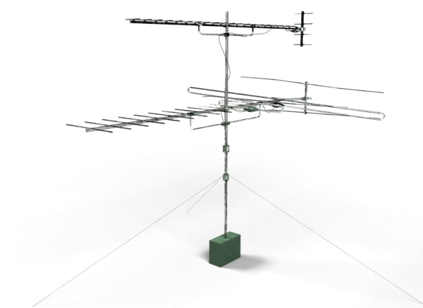 Bulk prints antennas for subscriber devices (GPS, LTE, etc.). Uses own Aerosol Jet printers. Very expensive industrial devices. The disadvantage is flat antennas.
2. Printing antennas on curved surfaces.
Illinois Materials Laboratory. Article short:
http://onlinelibrary.wiley.com/doi/10.1002/adma.201003734/abstract
Full text:
http://www.readcube.com/articles/10.1002%2Fadma.201003734?r3_referer=wol&tracking_action= preview_click&show_checkout=1&purchase_referrer=onlinelibrary.wiley.com&purchase_site_license=LICENSE_DENIED_NO_CUSTOMER
They printed the antenna onto a glass case using conductive aerosols.
Conductive aerosol printing technology. The article provides an analysis of the characteristics of the resulting antennas. There are no further publications by these authors.
3 . Denmark. Technical University of Denmark. Research group in the field of antennas, components and circuits in the microwave range. Contact link: http://www.ems.elektro.dtu.dk/about_us/contact_us
An article dated January 31, 2015 reports a prototype of a two-way periodic helical antenna that was printed in plastic and then coated with conductive paint. Photo result. Characteristics are not given.
This is the closest result to the required form factor. The main issue is that there is no single design manufactured in a single technical process. There are doubts about the identity of the resulting characteristics of antennas made separately of a dielectric base and a conductive spiral.
4. Domestic publication. Journal "Vector High Technologies" No. 6 (11) 2014 article "Aerosol printing on three-dimensional bases". The technology is described, there are examples of finished products of microelectronics, without details on the equipment used.
Modeling object, which is taken as the basis for the antenna
A small-sized microwave antenna is taken as an object for modeling and manufacturing a prototype, the design description of which and radio technical characteristics are published in the form of a report “Small-sized UHF helical antenna” in the materials of the All-Russian conference “Electronics and microelectronics of the microwave”, St. Petersburg, June 3-6, 2013. The author of the report N.V. Korobeinikov. The design of the antenna is a dielectric hemisphere with a truncated upper part, on which there is a printed circuit board with an arithmetic two-way spiral. On the surface of the hemisphere there is a double-threaded arithmetic spiral, which is galvanically connected on one side with the branches of a flat two-threaded spiral, and on the other hand with the metal base of the antenna. The antenna is powered by a slot balancing transformer. It is a metal coaxial cable with a cutout at the top.
The whole structure is on a metal base. Antenna output - СР-50-727. The dimensions will be specified based on the results of checking the parameters of the antenna, the approximate diameter and height were 50 mm. This design is very well suited for the task of developing 3D printing technology, primarily due to its size. In addition, the presence of elements of a flat antenna in the antenna design and the transition to a hemisphere allow you to immediately work out complex and ambiguous technological moments associated with the transition of the conductive layer from a plane to a hemisphere. In addition, the description of the antenna contains radio specifications that can be used when designing a 3D model of the antenna so that it matches real samples.
3D model of our antenna
The dimensions of the antenna elements were calculated in the HFSS application. Further, according to the obtained dimensions, a three-dimensional model was built in the KOMPAS application.
Manufacturing technology
At the moment, various options for manufacturing the antenna have been worked out. The most effective method seems to be in which the antenna body is made by 3D printing with plastic, and then spirals of conductive material are applied to the resulting body by the aerosol method. The matching transformer and connector are mounted in the provided cavities in the antenna housing.
In order to check the combination of different technologies for making the base, and the compatibility of the obtained samples with the technology of aerosol printing, it was decided to make the bases with two different technologies.
First selective laser sintering (SLS) technology. In this technology, the product is formed from a fusible powder material (plastic) by melting it under the action of laser radiation. To manufacture the base of the antenna, layer-by-layer selective (selective) sintering of polyamide powder was used on an EOS P39 installation.6. Material polyamide PA2200. Trademark registered by EOS GmbH (Electro Optical Systems, Germany). Material based on polyamide 12 (PA12) in white powder form.
Second stereolithography (SLA) technology. In SLA technology, the product is formed from a liquid photopolymer that hardens under the action of laser radiation. A distinctive feature of SLA is the high accuracy of sample execution. To manufacture the base of the antenna, layer-by-layer deposition and curing of the photopolymer resin with a YVO₄ laser with a wavelength of 354.7 nm on an RSPro 600 (UnionTech) was used. Used photopolymer resin UTR 9000. Material produced by UnionTech (Shanghai Union Technology Ltd. , China). Ivory liquid photopolymer resin.
Application of a conductive layer using spray technology. The conductive layer was deposited on an AJP-15XE aerosol printer from Neotech AMT (Germany).
The unit allows you to work with both three-dimensional and flat bases. The maximum nozzle travel speed is 2000 mm/min, the size of the working area is 650x450x250 mm (X Y Z). You can work with various materials, the requirements for ink viscosity are from 1 to 1000 cP (centipoise), the particle size in the ink is 0.5 microns. In a pneumatic atomizer, an aerosol is formed from the ink.
This happens as follows: in the cylinder inside the tank, the gas flow leaving the hole breaks the ink into microdroplets, thus forming an aerosol. Drops of too large size settle on the walls of the can and fall back into the total mass of ink. The gas flow at the outlet of the atomizer tank is too high to pass through the nozzle. Simply pumping out the gas would be inefficient, because. this consumes too much atomized material. Instead, an impactor is used, which concentrates the aerosol, removing excess atomizing gas from the system. The outlet of the impactor is directed to the print head. In the printhead, the aerosol stream is surrounded by a gas that accelerates and focuses the stream.
Aerosol Jet manufacturing process. The CAD model is converted into a DWG file for CNC operation. Liquid material (nanoparticles of a polymeric conductive material, dielectric, conductive epoxy material in a liquid) is placed in an ultrasonic or pneumatic atomizer, which creates a dense flow of particles with a size of 1-5 microns. A focused stream is delivered to the head with the help of protective gas and sprayed onto the substrate at high speed, creating elements up to 10 microns in size. The shielding gas also prevents material from sticking to the nozzle. Upon completion of printing, post-processing takes place - drying, curing, sintering.
Physics of the process. Conductive materials - Ag, Al, Au, Cu, Pt, Pd. The smaller the size of the nanoparticles, the lower the melting point, while the atoms on the surface of the particles are in a state of high energy, which allows them to combine with other particles (diffusion in the solid state) at lower temperatures. For example, for Ag: from 1000 C (in the normal state) to 150 C (sintering temperature) for nanoparticles.
To test the combination of technologies, two samples of the base were made from one sample of SLA and SLS.
Next, a layer of metallization was applied to each of them. Already at this stage, it became clear that the base made using the SLS technology is much worse combined with the technology of applying metallization due to the surface roughness. As a result, the conductive ink spread more on the surface, and this affected the electrical characteristics and quality of the sample.
For this reason, a sample with a base made using SLA technology was used in further development.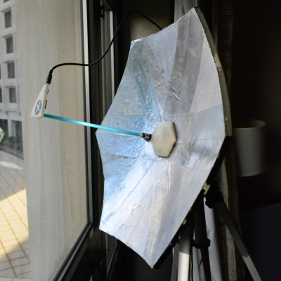
Mounting the antenna
As a result, we collected one sample and even tried to measure the parameters. Unfortunately, it was not possible to obtain acceptable radio technical characteristics on the first sample. This means that it is necessary to conduct a study of the electrical characteristics of the obtained materials and, on the basis of these data, to model the geometric dimensions of the antenna in software products specially designed for this. And of course, the specifics of product development for high frequency ranges is such that after the most accurate modeling and manufacturing, 'finishing with a file' is required. Those. in our case, this means that the 3D model must go through several iterations of refining the geometric parameters in order to obtain the required radio performance. Of course, it would be very interesting to do all this, but the financial opportunities available to us were only enough for the presented result.
Based on the experience gained in working on the antenna, we see the following prospects for the use and development of this technology:
1. The main direction is the manufacture of various elements of electronic circuits, including antennas, sensors, drives of actuators on plastic bases of complex shape. At the same time, the technology is compatible with industrial methods of mounting elements.
2. Solving specific problems such as "smart skin" (applying antennas, sensors, etc. on the surfaces of objects, such as drones) or the task of matching the antenna-radome system (when the antenna can be 'printed' directly on the inner surface of the fairing.
3. Research tasks related to the manufacture of small-sized antennas or even antenna arrays with a given radiation pattern due to the complex shape of antenna elements or the use of dielectrics with a given inhomogeneous permittivity in antenna bases.
3D and 3G: printing antennas
We print
Subscribe to the author
Subscribe
Don't want to
6
One of the most important advantages of 3D printers is the ability to accurately reproduce the dimensions of the model.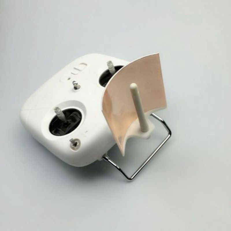 A radio amateur can use it to facilitate the creation of antennas. Of course, a typical 3D printer will not be able to print the conductive elements of antennas, as well as very large parts of HF antennas, but for the gigahertz bands it is quite possible to create templates and support structures, which is what I want to demonstrate in this article. For example, the 2100 MHz band is selected, which is used for cellular communications in the 3G standard (specialists, please do not kick me for such a wording, this is scientific pop).
The models are made in openSCAD and parameterized so that they can be easily converted to other frequencies (eg 4G 1800MHz or 2600MHz, Wi-Fi 2400MHz).
I myself live in a village, so communication problems are familiar to me firsthand. Also, I'm a radio amateur. Well, the presence of a 3D printer gave an impetus to creativity. A cheap "whistle" modem with an antenna output completed the picture.
Cantenna, aka Banktenna
One of the simplest structures that can, in principle, be made from a beer can, and it does not need to be soldered: just stick a "whistle" to the desired depth.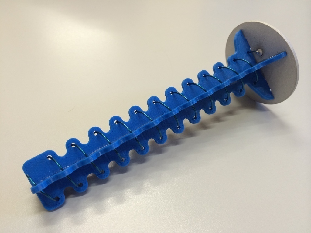 But for our range, it is not so easy to find a can of the right size: you need to find beer in a liter can, which is difficult in rural conditions. So I sketched the model and printed it. I had to divide the cylinder into three parts: firstly, it did not fit entirely into the limitations of my printer in height, and secondly, I reasoned that when printing tall, thin-walled parts, problems could begin, leading to deformation. It turned out the following.
Cut-out segment - 2 pcs.
Segment without cutout - 1 pc.
Racks - 2 pcs.
I printed (slightly simplified for speed):
I glued the cylinder with foil and assembled:
Everything, the antenna is ready.
Of course, its gain is not so hot (3-6dBi), but with such ease of manufacture and use, as they say, what did you want from under it? Nevertheless, she found her place in one of the neighboring houses: there the modem did not catch almost at all, except in good weather, and with it it stably finds the network and squeezes 1-2 Mbps out of it.
Biquad, also known as a zigzag, also known as Kharchenko's antenna
This antenna is a bit more complicated: you have to solder. But it also gives a little more gain (7-10dBi).
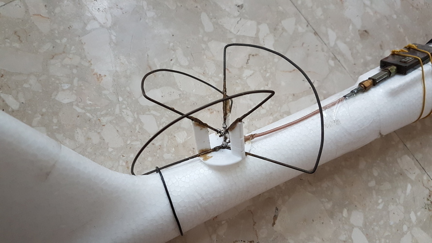
In this design, the dimensions of the vibrator (hussars, be silent!) and the distance to the reflector are important. This template will allow you to comply with them:
We paste it in the center on a metal plate or something even and glued with foil. We bend the vibrator from the wire and adjust it to the template. We drill a hole, thread the wire from the modem and solder it to the vibrator.
The feet will keep the product upright.
Theoretically, you can add a rod for the director system to increase the gain, but this is, let's say, an amateur. I didn't do it. The antenna worked for me for more than a year, until I bought a cool 4G dish on the roof. The modem squeezed out of a frail signal up to 3 Mbps.
Yagi, aka Uda-Yagi, aka wave channel
This antenna is "scalable", that is, it can be extended to get better gain. Its manufacture is relatively difficult, it is important to observe the dimensions, in addition, you will have to calculate and manufacture a matching transformer ("balun"). A 3D printer will help us with the dimensions.
I drew a 6-directory board, it just fits on the table. The gain should be around 10-12dBi.
It remains to cut and bend the appropriate elements of the wire and "fit" them into the template.
I made a simpler version: I can cut and bend the wire to size with my hands, I printed only a longitudinal bar ("boom").
Directors and vibrator made of copper wire are inserted into the holes and, if necessary, fixed with glue.
Let's make a stand:
I did not have a chance to test the antenna - with the installation of a good commercial solution, the need for a "collective farm" disappeared. So if anyone gets confused by this option - unsubscribe how good it is in design and operation..
That's it.