Fdm technology 3d printer
Fused Deposition Modeling - FDM 3D Printers
Fused Deposition Modeling - FDM 3D Printers - Stratasys Stratasys Invests in Axial3D to Make Patient-Specific 3D Solutions Available to All - Learn MoreUSA & Canada
Select your country and region
- Americas
- English
- Español (México)
- Português (Brasil)
- EMEA
- English (United Kingdom)
- Deutsch
- Español
- Français
- italiano
- APAC
- 中文(简体)
- 日本語 (日本)
- 한국어(대한민국)
- English (India)
USA & Canada
Stratasys FDM Technology
As the leader in the 3D printing industry, Stratasys has developed a wide range of innovative solutions that enable manufacturers, engineers, designers, inventors, educators, and dreamers to create things more effectively and efficiently.
FDM (Fused Deposition Modeling) originally invented and patented by Stratasys founder Scott Crump in 1989. Fast forward to the present, FDM is now the most commonly used 3D printing process.
What is FDM Technology?
FDM technology is the process of making physical objects by building up successive layers of material. A thermoplastic filament is pushed through an extruder and deposited where needed in each layer to complete the desired object.
At its core is an additive manufacturing (AM) method or process opposite of traditional manufacturing which is subtractive, involving cutting away at a block of material to produce an object.
3D printing with FDM technology is clean, simple to use, and office friendly. Thanks to production grade materials that are mechanically and environmentally stable. They include many of the same tried-and-tested thermoplastics used in traditional manufacturing processes like injection molding.
With Stratasys FDM technology, making complex geometries and parts with internal cavities becomes possible.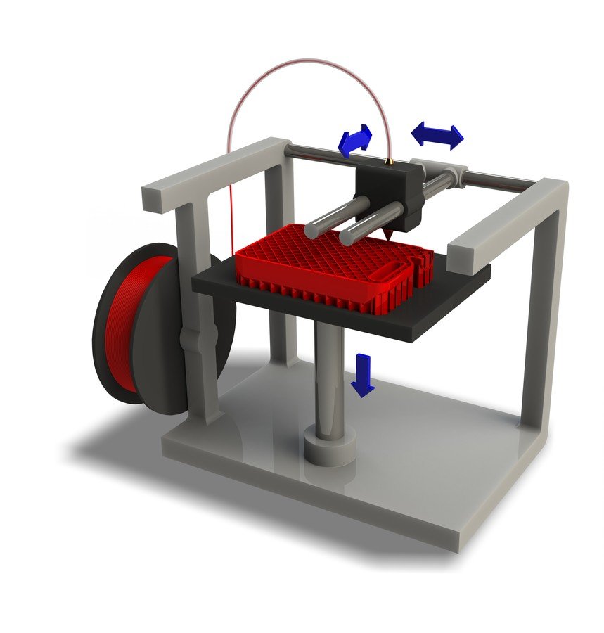 For applications that demand precise tolerances, durability, and stability in different environments, FDM thermoplastics deliver the required properties.
Benefits and Advantages of FDM?
There are many benefits and advantages associated with FDM 3D printing technology. To help guide manufacturers interested in leveraging FDM Technology, check out various resources here. You’ll also find validation from world leading brands that took the leap forward into innovating their product development and business operations with this technology.
Benefits of FDM Technology
- The technology is clean, simple-to-use and office-friendly.
- Reduce production expenses with Stratasys FDM technology.
- Manufacturing with FDM technology results in shorter lead times (get to market faster.)
- Supported production-grade thermoplastics are mechanically and environmentally stable.
- Complex geometries and cavities that would otherwise be problematic become practical with FDM technology.
Advantages of FDM Technology
- Precision - Trusted repeatability and relability with engineer-grade percision.
- Strength - Multiple options of high-performance for applications that require element resistances.
- Large Build Capacity - Browse our 3D Printer Catalog, download the brochures to view specs.
- Material Variety - Best-in-class material portfolio, offering engineer-grade thermoplastics.
- Rapid Turnaround - FDM Parts skip tooling, reducing lead times from weeks to days.
- Part Production - Produce end-use parts on-demand.
What is FDM 3D Printing? It's an Additive Manufacturing Process
FDM 3D Printers helped Sierra Space ready the '
Dream Chaser' for commercial spaceflight.
"3D Printing has been very effective at helping us produce the 'Dream Chaser' vehicle. We largely use Stratasys and their machines to help us develop tooling; specifically locating fixtures. " - Bill James
Senior VP & GM
Space Transportation Sierra Space
"We have to produce these chucks for basically every tile, we have thousands of them on this vehicle. In the Analysis we did it very quickly built a case for using 3D printing to do these chucks. We're looking at tens of thousands hours of saved." - Bob Gjestvang
Lead Manufacturing Engineer
Thermal Protection & Propulsion Group Sierra Space
Another Reason to Pick Stratasys
Learn the best additive manufacturing solutions for your brand, no matter the industry.
FDM 3D Printers, Materials, and Services
FDM Printers
3D printers that run on FDM Technology build parts layer-by-layer from the bottom up by heating and extruding thermoplastic filaments.
View all FDM printers
FDM Materials
FDM Technology uses the same tried and tested thermoplastics found in traditional manufacturing processes. For applications that demand tight tolerances, toughness and environmental stability - or specialized properties like electrostatic dissipation, translucence, biocompatibility, VO flammability or FST ratings - there's an FDM thermoplastic that can deliver.
View all FDM Materials
FDM On Demand
Empower innovation with manufacturing services and a team of experts from Stratasys Direct Manufacturing.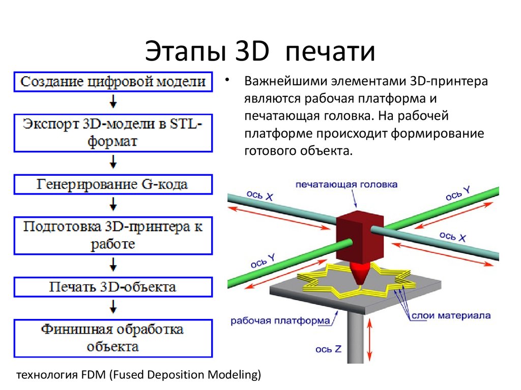
Learn more
3D Printed Robot Arm using ULTEM™ 9085 resin with Stratasys FDM Technology - Industrial 3D Printing Solutions.A 3D printed machining fixture made from FDM Nylon-CF10 materialA 3D printed machining fixture made from FDM Nylon-CF10 material.Launch vehicle ECS duct 3D printed in ULTEM™ 9085 resin material.FDM 3D printed automotive dashboard frame.Large prototype appliance part 3D printed on a large-format F770 FDM printer.3D Printed Fuel Pipe Fixture. Material used ABS CF-10, produced on a Stratasys 3D Printer.3D Printed Dumbbells' using material ASA-ABS. Produced from a Stratasys FDM 3D Printer.3D Printed Electric Exterior Outlet. Produced with a Stratasys FDM 3D Printer, from ASA Material.FDM Technology - 3D Printed Using Diran, End Use 3D Printed Robot Arm.3D Printed from Nylon CF10 using Stratasys FDM Technology - 3D Printing Solutions.3D Printed from ULTEM™ 1010 resin using Stratasys FDM Technology - 3D Printing Industrial Solutions. 3D Printed Part - ULTEM™ 1010 - FDM AI Composite Tooling3D Printed part - ultem 1010 fdm ai composite tooling3D Printed ultem 9085 - fdm mv exhaust side3D Printed digital abs plus part3D Printed Car Taillight3D Printed absplus control penels3D Printed absplus planetary gear3D Printed robot controlled vacuum gripper
Made with FDM 3D Printing Technology
Related content
How companies optimize for realistic prototyping.
In this whitepaper, you'll learn everything you need to know about the Connex3 and how companies use those features to optimize realistic prototyping.
View more
Dental 3D Printing
Stratasys 3D Printing Solutions for Digital Dentistry enhance the patient experience and your business. No more wasted time, materials, or storage space.
View more
What is FDM (fused deposition modeling) 3D printing?
Interested in learning the basics of FDM 3D printing? In this article, we explain why this technology is an efficient and cost-effective choice for rapid prototyping and other applications.
Fused deposition modeling (FDM) 3D printing, also known as fused filament fabrication (FFF), is an additive manufacturing (AM) process within the realm of material extrusion. FDM builds parts layer by layer by selectively depositing melted material in a predetermined path, and uses thermoplastic polymers that come in the form of filaments.
Composing the largest installed base of desktop and industrial-grade 3D printers worldwide, FDM is the most widely used technology and likely the first process you think of when 3D printing comes up.
Curious about the price of FDM 3D printing?
Our FDM 3D printing services Upload a CAD for a free, instant FDM quote
In this article, we cover the basic principles and key characteristics of this popular additive technology. We also explore the differences between FDM machines built for desktop and industrial applications and provide tips and tricks for engineers to get the best results from FDM 3D printing.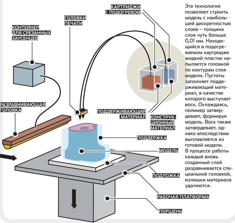
Watch before you read: how to prototype like a pro with FDM 3D printing
This video breaks down how to use FDM 3D printing for rapid prototyping.
How does FDM 3D printing work?
An FDM 3D printer works by depositing melted filament material over a build platform layer by layer until you have a completed part. FDM uses digital design files that are uploaded to the machine itself and translates them into physical dimensions. Materials for FDM include polymers such as ABS, PLA, PETG and PEI, which the machine feeds as threads through a heated nozzle.
To operate an FDM machine, you first load a spool of this thermoplastic filament into the printer. Once the nozzle hits the desired temperature, the printer feeds the filament through an extrusion head and nozzle.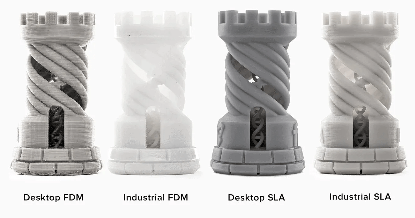
This extrusion head is attached to a three-axis system that allows it to move across the X, Y and Z axes. The printer extrudes melted material in thin strands and deposits them layer by layer along a path determined by the design. Once deposited, the material cools and solidifies. You can attach fans to the extrusion head to accelerate cooling in some cases.
To fill an area, multiple passes are required, similar to coloring in a shape with a marker. When the printer finishes a layer, the build platform descends and the machine begins work on the next layer. In some machine setups, the extrusion head moves up. This process repeats until the part is finished.
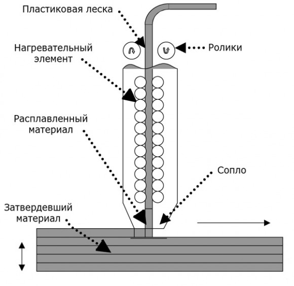
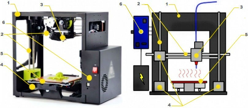
Schematic of a typical FDM printerWhat are the print parameters for FDM 3D printers?
Most FDM systems allow you to adjust several process parameters. These include the nozzle and build platform temperatures, build speed, layer height and cooling fan speed. If you’re a designer, you normally don’t have to worry about these adjustments, as an AM operator probably already has that covered.
Factors that are important to consider, though, are build size and layer height. The common build size of a desktop 3D printer is 200 x 200 x 200 mm, while industrial machines can reach sizes of 1,000 x 1,000 x 1,000 mm. If you prefer to use a desktop machine to print your part, you can break down a big model into smaller parts and then reassemble it.
FDM’s typical layer height ranges between 50 and 400 microns. Printing shorter layers produces smoother parts and more accurately captures curved geometries, though printing taller layers means you can create parts quickly and for a lower price tag.
Design tip: A smart compromise we recommend is to print layers 200 microns thick. Want to know more? Check out our article on the impact of layer height on 3D printed parts .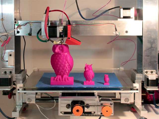
Is there a difference between desktop and industrial FDM printers?
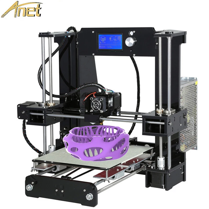
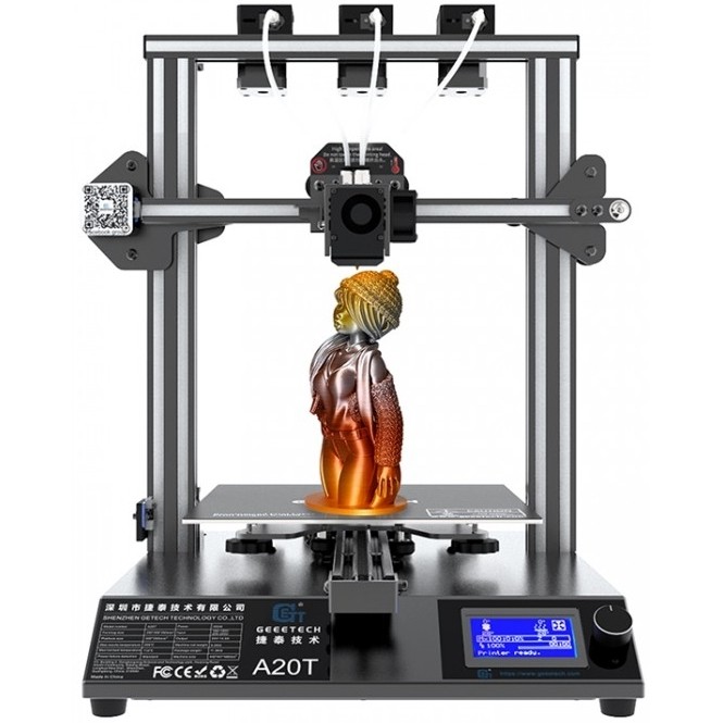
FDM printers generally fall into two main categories: industrial (also called professional) and desktop (also called prototyping) machines. Both printer grades have distinct applications and advantages, though the main difference between the two technologies is their scale of production.
Industrial FDM 3D printers, like the Stratasys 3D printer, are far more expensive than their desktop counterparts - desktop machines being mostly for at-home, consumer use - so using them for your custom parts will run up a higher tab. As industrial machines are more efficient and powerful than desktop FDM printers, they are more often used for tooling, functional prototypes and end-use parts.
As well, industrial FDM printers can complete larger orders much faster than desktop machines. They are designed for repeatability and reliability and can produce the same part over and over with minimal human intervention. Desktop FDM printers are not nearly as robust. With desktop machines, you have to perform frequent user maintenance and regular calibration.
In the table below, we break down the main differences between a typical desktop FDM machine and an industrial one.
| Property | Industrial FDM | Desktop FDM |
|---|---|---|
| Standard accuracy | ± 0.15% (lower limit ± 0.2 mm) | ± 1% (lower limit: ± 1.0 mm) |
| Typical layer thickness | 0.18 - 0.5 mm | 0.10 - 0.25 mm |
| Minimum wall thickness | 1 mm | 0.8 - 1 mm |
| Maximum build envelope | Large (e.g. 900 x 600 x 900 mm) | Medium (e.g. 200 x 200 x 200 mm) |
| Common materials | ABS, PC, ULTEM | PLA, ABS, PETG |
| Support material | Water-soluble/Break-away | Same as part (typically) |
| Production capabilities (per machine) | Low/Medium | Low |
| Machine cost | $50000+ | $500 - $5000 |
What are the characteristics of FDM 3D printing?
While FDM 3D printers vary in terms of their extrusion systems and the part quality you get from various machines, there are common characteristics that you can expect from every FDM printing process.
Warping
Warping is one of the most common defects in FDM. When extruded material cools during solidification, its dimensions decrease. Since different sections of the printed part cool at different rates, their dimensions also change at different speeds. Differential cooling causes the buildup of internal stresses that pull the underlying layer upward, causing it to warp.
There are several ways to prevent warping. One method is to closely monitor the temperature of your FDM system, especially the build platform and chamber. You can also increase the adhesion between the part and the build platform to mitigate warping.
Making certain choices during the design process can also reduce the likelihood of your part warping. Here are a few examples:
-
Large, flat areas - like you’d see on a rectangular box - are more prone to warping. Try to avoid these whenever possible.
-
Thin protruding features - think of the prongs on a fork - are also prone to warping.
 Adding extra guiding or stress-relieving material at the edges of thin features to increase the area that makes contact with the build platform helps to avoid this.
 -
Sharp corners warp more often than rounded shapes, so we recommend adding fillets to the design.
-
Every material has its own susceptibility to warping. For instance, ABS is generally more sensitive to warping than PLA or PETG, for instance.
Layer adhesion
Secure adhesion between deposited layers of a part is critical in FDM. When an FDM machine extrudes molten thermoplastic through the nozzle, this material presses against the previously printed layer. High temperature and pressure cause this layer to re-melt and enable it to bond with this previous layer.
And since the molten material presses against the previously printed layer, its shape deforms to an oval. This means that FDM parts always have a wavy surface, no matter what layer height is used, and that small features, such as small holes or threads, may require post-processing.
The FDM material extrusion profile.Support structure
FDM printers can’t feasible deposit molten thermoplastic on thin air. Certain part geometries require support structures, which are usually printed in the same material as the parts themselves.
Oftentimes, removing support structure materials can be difficult, so it’s often far easier to design parts in such a way that minimizes the need for support structures. Support materials that dissolve in liquid are available, but you generally use them in tandem with higher-end FDM 3D printers.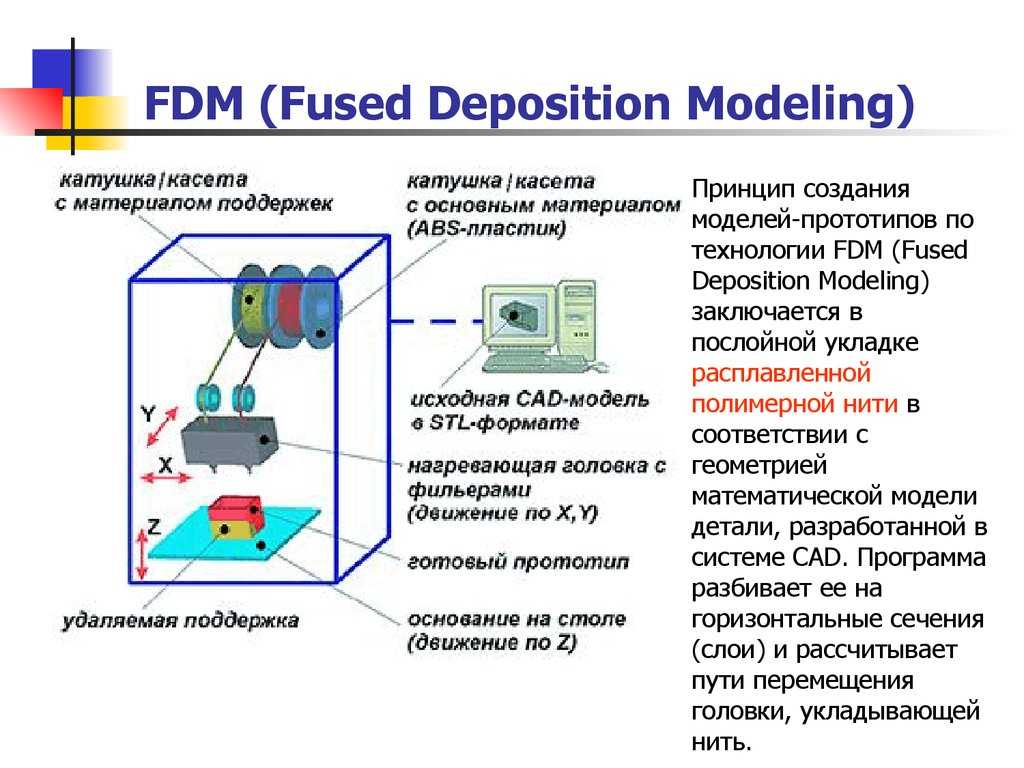 Be aware that using dissolvable supports will increase the overall cost of a print.
Infill and shell thickness
To reduce print time and save on materials, FDM printers usually don’t produce solid parts. Instead, the machine traces the outer perimeter - called the shell - over several passes, and fills the interior - called the infill - with an internal, low-density structure.
Infill and shell thickness significantly affect the strength of FDM-printed parts. Most desktop FDM printers have a 20% infill density default setting and 1 mm shell thickness, which provides a suitable compromise between strength and speed for quick prints.
The internal geometry of FDM prints with different infill densityThe table below summarizes the main characteristics of FDM 3D printing.
| FDM | |
|---|---|
| Materials | Thermoplastics (PLA, ABS, PETG, PC, PEI etc) |
| Dimensional Accuracy | ± 0.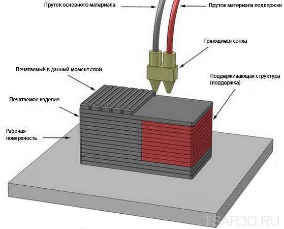 5% (lower limit ± 0.5 mm) - desktop 5% (lower limit ± 0.5 mm) - desktop± 0.15% (lower limit ± 0.2 mm) - industrial |
| Typical Build Size | 200 x 200 x 200 mm - desktop 900 x 600 x 900 mm - industrial |
| Common layer thickness | 50 to 400 microns |
| Support | Not always required (dissolvable available) |
What are common materials for FDM 3D printing?
One of the key advantages of FDM (both desktop and industrial) is the technology’s wide range of materials. This includes commodity thermoplastics such as PLA and ABS, engineering materials like PA, TPU and PETG and high-performance thermoplastics, including PEEK and PEI.
PLA filament is the most common material used in desktop FDM printers. Printing with PLA is relatively easy and can produce parts with finer details. When you need higher strength, ductility and thermal stability, you normally use ABS. However, ABS is more prone to warping, especially if you are using a machine that doesn’t have a heated chamber.
Another alternative for desktop FDM printing is PETG, which is comparable to ABS in its composition and how easy it is to print with. All three of these materials are suitable for most 3D printing service applications, from prototyping to form, fit and function, to low-volume production of models or functional parts.
Industrial FDM machines, on the other hand, mainly use engineering thermo-plastics, including ABS, polycarbonate (PC) and Ultem. These materials usually come equipped with additives that alter their properties and make them particularly useful for industrial needs like high impact strength, thermal stability, chemical resistance and biocompatibility.
Printing in different materials will affect your part’s mechanical properties and accuracy, as well as its cost. We compare the most common FDM materials in the table below.
| Material | Characteristics |
|---|---|
| ABS | + Good strength + Good temperature resistance - More susceptible to warping |
| PLA | + Excellent visual quality + Easy to print with - Low impact strength |
| Nylon (PA) | + High strength + Excellent wear and chemical resistance - Low humidity resistance |
| PETG | + Food Safe* + Good strength + Easy to print with |
| TPU | + Very flexible - Difficult to print accurately |
| PEI | + Excellent strength to weight + Excellent fire and chemical resistance - High cost |
For more details, see this review of the main differences between PLA and ABS —the two most common FDM materials—and an extensive comparison of all common FDM materials.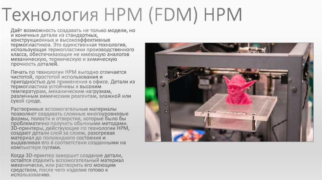
Post-processing for FDM 3D printing
FDM 3D printed parts can be finished to quite a high standard via several post processing methods, including sanding and polishing, priming and painting, cold welding, vapor smoothing, epoxy coating and metal plating.
Interested in exploring all the post-processing options for your next production run of FDM parts? Read our extensive guide to what’s available.
What are the best practices for printing with FDM?
-
FDM can produce prototypes and functional parts quickly and cost effectively.
-
There is a wide range of materials available for FDM.
-
Typical build size of a desktop FDM 3D printer is 200 x 200 x 200mm. Industrial machines have a larger build size.
-
To prevent warping, avoid large flat areas and add fillets to sharp corners.
-
FDM is inherently anisotropic, so it is unsuitable for mechanically critical components.
-
The minimum feature size of FDM machines is limited by the diameter of the nozzle and the layer thickness.
-
Material extrusion makes it impossible to produce vertical features (in the Z direction) with geometry smaller than the layer height (typically 0.1 - 0.2 mm).
-
FDM typically can’t produce planar features (on the XY plane) smaller than the nozzle diameter (0.4 - 0.5 mm).
-
Walls have to be at least 2 to 3 times larger than the nozzle diameter (i.e. 0.8 - 1.2 mm).
-
If you’re looking to produce smooth surfaces and very fine features, you may need additional post-processing, like sandblasting and machining.
 Another AM technology like SLA may be more suitable in this case.
Ready to get your parts into production? Head to the Hubs platform and we'll build an instant quote for all your FDM 3D printing needs.
Ready to transform your CAD file into a custom part? Upload your designs for a free, instant quote.
Get an instant quoteFDM technology. How it works.
Hello everyone, 3DTool is with you!
In this article on 3D printing, we will look at the basic principles of FDM (Fused Deposition Modeling) technology. Let's deal with the basic mechanics of this process. Its advantages and limitations.
FDM technology
Overlay printing (FDM) is an additive manufacturing process that is realized through the extrusion of materials. In FDM, an object is built by applying molten material according to a predetermined algorithm, layer by layer. The materials used are thermoplastic polymers and are filament-shaped.
FDM is the most widely used 3D printing technology. FDM printers are on the market in a wide variety. It's basically the first technology people come across when they start working with 3D. The following will introduce the basic principles and key aspects of this printing method.
An engineer who designs a 3D model should take into account the possibilities of technology when manufacturing a part with FDM, this knowledge will help him achieve the best result.
Process FDM printing
Here is how the FDM process works:
A spool of thermoplastic filament is loaded into the printer. Once the nozzle reaches the required temperature, the filament is fed into the extruder and into the nozzle where it is melted.
The extruder is attached to a 3-axis system that allows it to move in the X, Y and Z directions. The molten material is extruded in thin filaments and melted in layers at predetermined locations where it then cools and solidifies. Sometimes the cooling of the material is accelerated by the use of fans attached to the extruder.
The extruder requires several passes to fill the printable area. When the layer is finished, the platform moves down (or, as in some printer models, the extruder moves up), and a new layer is welded onto the already set one. This process is repeated until the entire model is printed.
FDM printer specifications
Most FDM systems allow you to adjust several parameters of the printing process. Such as nozzle temperature, platforms, print speed, layer height and cooling fan speed. These are usually set by the printer operator and do not bother the modeler.
What is important from a modeling standpoint is to consider the size of the table and the layer height of the part itself:
The standard printable area of a desktop 3D printer is usually 200 x 200 x 200 mm, while for industrial machines it can be up to 1000 x 1000 x 1000 mm. If a desktop 3D printer is preferable (e.g. for cost reasons), the large model can be broken down into smaller pieces and then reassembled/glued together.
The typical layer height used in FDM varies from 50 to 400 microns and can be determined during the software slicing step. A lower layer height will provide a smoother detail and more accurately represent complex geometry, while a higher layer height will print the part faster and at a lower cost. The layer height of 150-200 microns is optimal in terms of the ratio of printing time and its quality.
Part deformation
Warp is one of the most common defects in the FDM printing process. Some plastics shrink during cooling after extrusion. Since different regions cool at different rates, their dimensions can also change at different rates. Differential cooling causes an accumulation of internal stresses that pull the layer, the one from the bottom - up, deforming it, as shown in the figure below. From a technical point of view, deformation can be prevented by more careful control of the temperature of the platform and the chamber as a whole. By increasing the adhesion between the part and the platform.
The modeler can also reduce the chance of peeling and other warp-related defects:
Large flat areas (such as a rectangular box) are more prone to deformation and should be avoided if possible.
Thin protruding elements (for example, battlements, spiers) are also prone to deformation. In this case, it can be avoided by adding some support material around the edge of the thin element (for example, a 200 micron thick rectangle) to increase the contact area.
Sharp corners deform more often than rounded shapes, so smoothing the corners slightly can achieve a good result.
Different plastics are more susceptible to deformation: ABS is generally more sensitive to this factor than PLA or PETG due to its higher glass transition temperature and relatively high coefficient of thermal expansion.
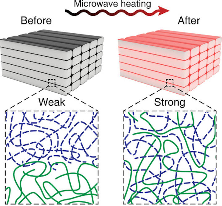
Adhesion between layers
Good adhesion between layers is very important for an FDM printed part. As the molten plastic is extruded through the nozzle, it is pressed against the previous layer. High temperature and pressure remelt the surface of the previous layer and allow the new layer to bond with the old one.
The strength of the bond between different layers is always lower than the basic strength of the material.
This means that FDM parts are inherently anisotropic: their Z strength is always less than their X/Y strength. For this reason, it is important to keep the orientation of parts in mind when designing.
For example, tensile test specimens printed horizontally with ABS at 50% infill were compared with test specimens printed vertically and found to have nearly 4 times higher tensile strength in the X, Y axis compared to the Z axis ( 17.0 MPa compared to 4.4 MPa).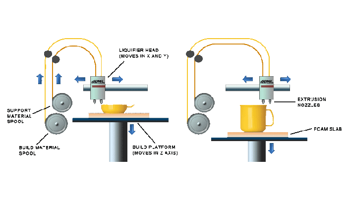 Such a part is stretched to failure, almost 10 times more (4.8% compared to 0.5%).
Moreover, since the molten material is pressed against the previous layer, its shape is deformed to an oval. This means that parts will always have a wavy surface, even at low layer heights, and that small features, such as small holes, may need post-printing post-processing.
Supports
The support structure is essential for creating tab geometries. Because plastic cannot be applied to air, some geometries require a support structure.
Surfaces printed with supports are usually of lower quality than the rest of the part. For this reason, it is recommended that the part be modeled in such a way as to minimize the need for support.
Supports are usually printed from the same material as the part. There are also specialty materials that dissolve in liquid, but these are mostly used in high-end desktop or industrial 3D printers.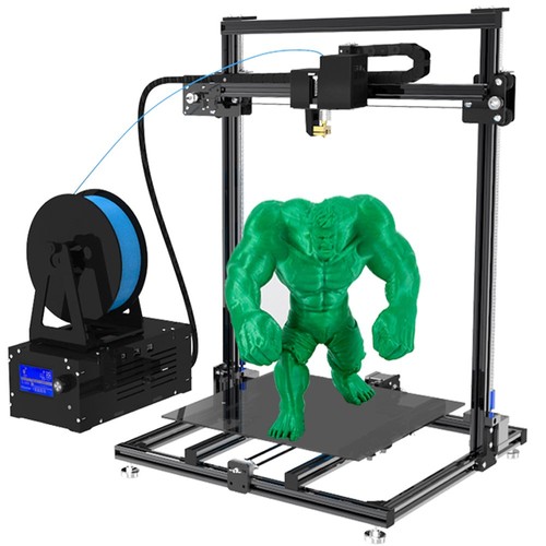 Printing on soluble supports greatly improves the surface quality of the part, but increases the overall cost of printing because a special printer with two print heads is required and because the cost of the soluble material is relatively high.
Filling and shell thickness
FDM parts are usually not printed full in order to reduce printing time and save material. Instead, the outer perimeter is made with several passes, it is called a shell, and the inner part is filled with a low density structure called infill.
The filling and thickness of the body greatly affect the strength of the part. For desktop FDM printers, 25% infill density and 1mm body thickness are mostly suitable. Usually, these are the standard settings for fast printing and a good compromise between strength and speed.
Above you can see the internal geometry of parts with different degrees of filling
FDM Essential Consumables
One of the strengths of FDM printing is the wide range of materials available. They can range from conventional plastics (such as PLA and ABS) to engineering plastics (such as TPU and PETG) and high strength materials (such as PEEK).
Below is a pyramid of materials most available in FDM printing.
The material used directly affects the mechanical properties and accuracy of printing, as well as its price. The most common FDM printing materials are listed below. We will also consider the pros and cons of certain plastics. An overview of the main differences between PLA and ABS, and a detailed comparison of all common types of filament is a very extensive topic and can be found in special articles on the Internet and on thematic forums.
ABS
pros
· Durability
Good temperature resistance
Minuses
Shrinks when printed
PLA
pros
Excellent visual quality
Easy to print
· Unharmful. May come into contact with food
Minuses
· Low impact strength
· Longevity
Nylon
pros
· Very high strength
Excellent wear and chemical resistance
Minuses
· Actively absorbs water
PET-G
pros
· Unharmful. May come into contact with food
Sufficiently strong
Minuses
Capable of precise temperature print settings
TPU
pros
· Very flexible
Minuses
Printing accuracy is very difficult to achieve
PE EK
pros
· Extremely durable and lightweight
Excellent flame retardant and chemical resistance
Minus
· High price
Need a specialized 3D printer whose extruder is capable of reaching temperatures above 300C
Postprocessing
FDM parts can be processed to high standards. When using various methods such as: sanding, polishing, priming, painting, cold welding, acetone bath (to smooth the surface and create a glossy surface), epoxy coating and plating.
Advantages and disadvantages of FDM printing
+
· FDM printing is the most economical way to produce custom thermoplastic parts and prototypes.
· FDM printing lead time is acceptable. The technology is quite affordable these days.
Wide range of materials suitable for both prototyping and some non-commercial functional applications.
-
FDM printing has the lowest dimensional accuracy and resolution compared to other 3D printing technologies, so it is not suitable for models with complex geometry and fine details
The final product will have visible layer lines, so post-processing is required for a better look
Layer adhesion mechanism makes FDM printed parts anisotropic
Highlights
· With FDM printing, prototypes and functional parts can be produced quickly and at a low cost.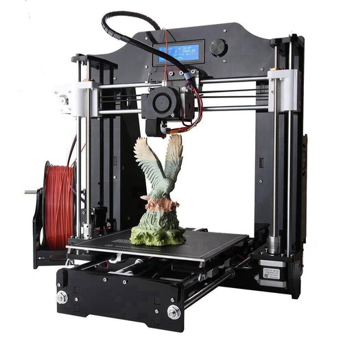 There is a wide range of filaments on the market with different physical properties.
· The typical platform size of a desktop FDM 3D printer is 200 x 200 x 200mm. Industrial machines are much larger. From 1000 x 1000 x 1000 mm
· To prevent part warping, cornering, etc., on plastics that have a shrinkage percentage, avoid large flat areas and add support at sharp corners greater than 45 degrees.
· An FDM printed part is inherently anisotropic, so it is not recommended to use such parts for mechanically important components.
Well!, And that's all we have! 3DTool was with you, see you in the next articles!
See 3D printers powered by FDM technology here
You can make a purchase, ask a question, or track your order on our website,
By mail: [email protected]
Or by phone: 8(800) 775-86-69
Don't forget to subscribe to our YouTube channel:
And to our groups in social networks:
In contact with
FDM 3D printing technology
FDM (Fused Deposition Modeling) is the most common 3D printing technology in the world.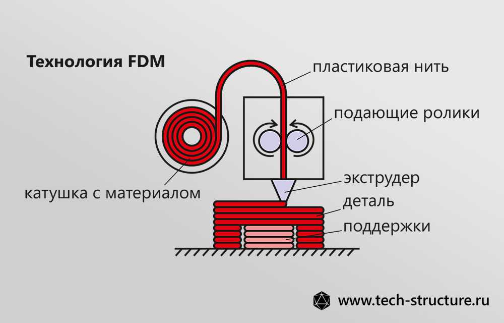 With its help, both cheap home printers and industrial high-precision 3D printing systems grow products. The principle of building according to FDM technology lies in the layer-by-layer growth of a product from a pre-melted plastic thread.
- How it works
- Printing examples
- Construction accuracy
- Choice of 3D printer
- Principle of operation
- Examples of print
- Construction accuracy
- Select 3D -printer
What is better to print: large products, which must be reliable in reliable properties ( ).
Advantages: strong wear resistant products, low material cost, high post-processing capabilities.
Alternative: MJM and PolyJet technologies, which with the help of special materials (ABS imitation) provide higher accuracy and surface quality of finished products (at a higher cost of printing).
What to print better: large items that must have reliable mechanical properties (strength, wear resistance, flexibility).
Advantages: strong wear resistant products, low material cost, high post-processing capabilities.
Alternative: MJM and PolyJet technologies, which with the help of special materials (ABS imitation) provide higher accuracy and surface quality of finished products (at a higher cost of printing).
How it works
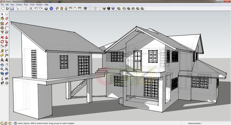
The 3D model in STL format is transferred to the 3D printer software. The program automatically (or the operator manually) places the model in the virtual space of the working chamber. Then the program automatically generates elements of auxiliary structures (from a special support material) and calculates the amount of consumables, as well as the prototype growing time. Before starting the printing process, the model is automatically divided into horizontal layers and the paths of the print head are calculated.
Then the direct 3D printing process starts: a heating head with dies (extruder) melts a thin plastic thread (fishing line) and lays it in layers according to the data of the mathematical 3D model.
After completion of the product building process, auxiliary structures are removed (manually or dissolved in a special solution). The finished product can be used in printed form or subjected to any post-processing method.
How it works
The 3D model in STL format is transferred to the 3D printer software. The program automatically (or the operator manually) places the model in the virtual space of the working chamber. Then the program automatically generates elements of auxiliary structures (from a special support material) and calculates the amount of consumables, as well as the prototype growing time. Before starting the printing process, the model is automatically divided into horizontal layers and the paths of the print head are calculated.
Then the direct 3D printing process starts: a heating head with dies (extruder) melts a thin plastic thread (fishing line) and lays it in layers according to the data of the mathematical 3D model.
After completion of the product building process, auxiliary structures are removed (manually or dissolved in a special solution). The finished product can be used in printed form or subjected to any post-processing method.
FDM Product Examples
Prototype air intake, ABS
Part of the engine cover
Master-model of dynamics, PLA
Prototype for tests, Ultem 9085
Copping for reverse engineering, ABS
Part of the case with support, ABS
of the airborne recruiter, prototype of the airborne collection. ABS
Motor housing part
Speaker master model, PLA
Test prototype, ULTEM 9085
Reverse engineering housing copy, ABS
Housing part with support, ABS
Building accuracy
The accuracy of building models using FDM technology largely depends on the thickness of the printed layer. This value can be from 0.127 to 1 mm. The surface of finished objects is usually slightly ribbed (stepped - within 0.