Dso138 3d printed case
▷ case for dso138 digital oscilloscope 3d models 【 STLFinder 】
Case for DSO138 digital oscilloscope
thingiverse
Before you try this design, please also look at this modified version: http://www.thingiverse.com/thing:1202909 This is a case for the DSO138 digital oscilloscope. This single channel 200kHz bandwidth 1 Ms/s oscilloscope is very simple, and is...
stand for DSO138 digital oscilloscope in case
thingiverse
I created a simple stand for the DSO138 case because i do not like my DSO138 lying flat on the bench. It is even stable with a proper probe attached and can quickly taken out if need to. Print Settings Printer Brand: ...
Enclosure for DSO138 digital oscilloscope
thingiverse
An enclosure for the DSO138 oscilloscope with room for a 9V battery.
Stand for DSO138 Digital Oscilloscope
thingiverse
Stand for DSO138 Digital Oscilloscope. Little bit of lazy print, i gleud it with some screws togheter. ...But working great!
Case stand for DSO138 Oscilloscope
thingiverse
Remixed case stand for DSO138 Oscilloscope.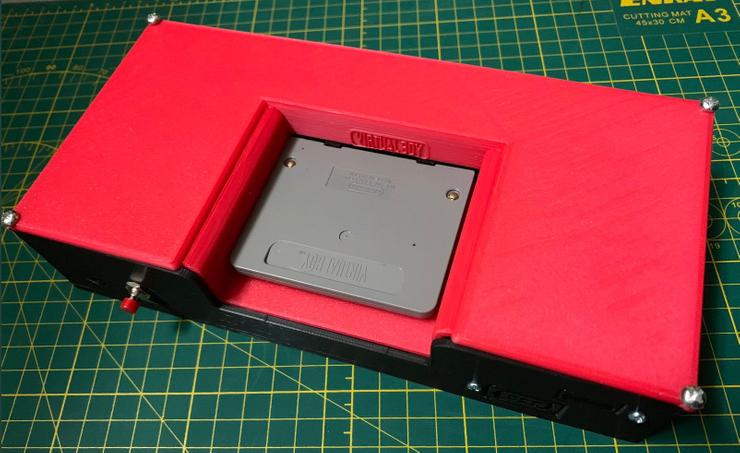 Maked in SolidWorks. ...Source in attachment.
Case stand for DSO138 Oscilloscope
thingiverse
Case stand for DSO138 Oscilloscope. - Two versions of front cover because i had used long tact switches when soldering. One version for long switches and other for default short switches. **Front cover printed with support**. Back cover -...
Case for Sainsmart DSO138 Oscilloscope Board
prusaprinters
This is a case for the Sainsmart DSO138 Digital Storage Oscilloscope board. All switches are accessible. The range slider switches have extenders on the left. Function push buttons on the right are molded into the case. Probe and power openings are...
Case for Sainsmart DSO138 Oscilloscope Board
thingiverse
This is a case for the Sainsmart DSO138 Digital Storage Oscilloscope board. All switches are accessible. The range slider switches have extenders on the left. Function push buttons on the right are molded into the case. Probe and power openings are...
Laser cutted acrylic case for DSO138 oscilloscope
thingiverse
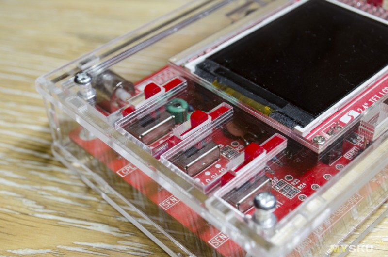
I share with you my DSO138 Chinese oscilloscope acrylic case. After much searching, I only found projects for 3D printer, as I only have access to a laser cutting machine, made one and share for a better world. In the project was used acrylic 2mm. ...I...
Case for Sainsmart DSO138 Oscilloscope Board
pinshape
SummaryThis is a case for the Sainsmart DSO138 Digital Storage Oscilloscope board. All switches are accessible. The range slider switches have extenders on the left. Function push buttons on the right are molded into the case. Probe and power...
DSO138 digital oscilloscope enclosure
thingiverse
This is a case for the famous DSO138 diy open source digital oscilloscope. Original design from thing 779159. I wanted to make some changes and I decided to redesign it. ...Print these buttons: 3 x button1 1 x button2 2 x slider1 1 x slider2
DSO138 oscilloscope case
thingiverse
Simple case for cheap oscilloscope module You`ll need: 1xDSO138 (can be obtained on ebay, aliexpress, etc..) 4x M3 screw 9V power supply Printed parts: 1x Top 1x Base 4x Button 3x Switch
DS0138 / DSO138 oscilloscope case / enclosure
thingiverse
This is a case designed for the cheap DS0138 / DSO138 oscilloscope.
DSO138 Digital oscilloscope front case
thingiverse
I just changed the lettering and placed another hole to better see the trigged LED, Also removed the lower corner name and written the model number.
Case for DSO138 mini DIY oscilloscope - H version
thingiverse
A simple DSO138 mini Jyetech DIY oscilloscope case for the H-version, which I recently bought from banggood. This is a remix from https://www.thingiverse.com/thing:3234032 which is for the J-version. (Thank you BETLOG!) The base is the same as...
USB Powered DSO138 Oscilloscope Case
thingiverse
This is my version of the DSO138 oscilloscope case that eliminates the 9V power port, and uses the USB for power. By doing this, the oscilloscope becomes ultra portable that can be powered using a USB power bank!
To do this, I bought a MT3608. ..
..
case - DSO138 mini oscilloscope 001
thingiverse
2018-11-24--00-30-04 - A case for the DSO138Mini oscilloscope. - IMPORTANT: NOT the "H" version, and probably NOT clones. Official Manual: https://jyetech.com/Products/LcdScope/UserManual_138mini.pdf shows title of "DN138-12v02" and Model:...
case - DSO138 mini oscilloscope 002
thingiverse
2018-12-30--14-42-55 - A case for the DSO138Mini oscilloscope. - The current evolution of https://www.thingiverse.com/thing:3234032 Separated into it's own thing for simplicity.
- Supports BNC probe connector, 18650 battery pack and switch.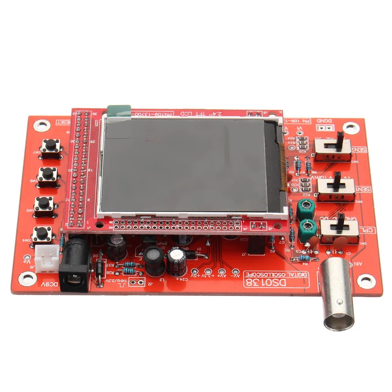 -...
-...
Simple stand for DSO138 oscilloscope
thingiverse
I designed this simple stand for my DSO138 oscilloscope. There are several more complex cases here but I wanted something quick and simple to print. ...You'll need 4 short self-tapping screws to build this.
Case for DSO138-Oszilloscope
thingiverse
This is a remix of https://www.thingiverse.com/thing:959009 i was not able to select this Thingi, so i do it here. ... I have created a version that can be orinted without any support cause it is made of two parts for the front casing.
Lithium cell powered DSO138 Oscilloscope Case
thingiverse
This is an 18650 cell powered case for the DSO138 mini oscillocope.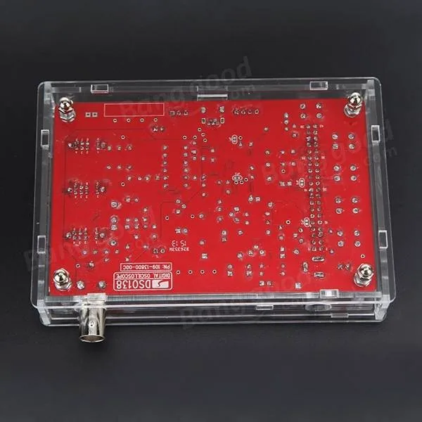 Charging is done by a standard TP4056 module. Apply some hot glue to keep it in place. A small boost converter is required to step the voltage to about 8V for the scope.
...
Wall holder for DSO138 case
thingiverse
This is remix/add-on of Case for DSO138 digital oscilloscope made by Egil. Simple two-part wall holder. Allows using of oscilloscope while mounted. Printed from PETG. ... Additional parts: 4pcs M3x12-30 countersunk screw
Case for JYETECH 062 Digital Storage Oscilloscope
thingiverse
I have no 100% tested model for you, but I'm 100% sure that this model is OK for the JYETECH 062 Digital Storage Oscilloscope. 4 hours later... Yes about that 100% sure ;-/ during a rebuild of a dangling sketch I had extruded it the wrong way. Sorry...
DS0138 Digital Oscilloscope Case
thingiverse
This is a casement I designed for the DS0138 digital oscilloscope. It's a cheap one channel O-Scope which comes with just a circuit board and leads, and nothing else. This case makes it look nice and gives it some protection. The original board...
Digital oscilloscope case
thingiverse
just built a cheap digital oscilloscope from ebay. ...Needed a case, so made one. ...If I did then someone else must as well :)
DSO138 case
thingiverse
It is just simple DSO138 case.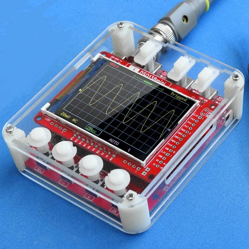
DSO138 Oscilloscope case with 9V battery and a power switch
thingiverse
This is an adaptation of the case for DSO138 oscilloscope that features a 9V battery and a rocker switch for power (none of that tumbler switch rubbish). Soldering is pretty simple and is shown on the pictures but feel free to ask questions. I had...
DSO138 Case
thingiverse
There are all the files to make the case for the DSO138. ...See my tutorial to assemble it: Print Settings Printer: Prusa I3 Rafts: . ..
..
DSO138 case
thingiverse
It is a customizable house for the DSO138. Behind there is even space for an on/off switch. it looks professional in my opinion. I advice to use a 0.4mm nozzle. ...Any print settings is fine for me but the switches and the buttons need to have a 100%...
DSO138 case
thingiverse
I can't close the case with the DSO138 inside, corners does not fit and not enough space left for the board. Had to make the board recess square, lowered the connector hole and also recess the corner tabs down further in the cover. Managed to reuse...
▷ dso138 case 3d models 【 STLFinder 】
DSO138 case
thingiverse
It is just simple DSO138 case.
DSO138 Case
thingiverse
There are all the files to make the case for the DSO138. ...See my tutorial to assemble it: Print Settings Printer: Prusa I3 Rafts: ...
DSO138 case
thingiverse
It is a customizable house for the DSO138. Behind there is even space for an on/off switch. it looks professional in my opinion. I advice to use a 0.4mm nozzle. ...Any print settings is fine for me but the switches and the buttons need to have a 100%...
DSO138 case
thingiverse
I can't close the case with the DSO138 inside, corners does not fit and not enough space left for the board. Had to make the board recess square, lowered the connector hole and also recess the corner tabs down further in the cover. Managed to reuse...
Simple DSO138 Case
thingiverse
Simple DSO138 case. Requires four 2*4mm hex bolts. ...And a switch.
DSO138 Case
prusaprinters
DSO138 case update
thingiverse
remix case for dso138https://www.chipdip.ru/product/dso138-kit Print Settings Printer: MC2
DSO138 Case parametric
thingiverse
Hier noch ein paar Links Schalter. ..
..
DSO138 Case with batterie
thingiverse
In case you don't like screws, there's a "glue-together"-version of the case here (without batterie): https://www.thingiverse.com/thing:3448128 print the "stick" three times and force it onto the original ones to extend them. The nuts will be...
DSO138 CASE REMIXED
thingiverse
this is a remix of https://www.thingiverse.com/thing:2545796 case thank you for the hard work on the case this is a remix of https://www.thingiverse.com/thing:2995281 with the battery case remix thank you for adding the battery compartment some times...
Yet another DSO138 case
thingiverse
Another DSO 138 oscilloscope case design, minimum parts required, easy to print. Just make sure your printer is calibrated to make exact size as model (mine require 100.7% x-y-scaling).
Vertical printings makes better surface and you don't have...
DSO138 Case - chunky
thingiverse
... legs. Reset button is flush with case to minimize mistakes. On/off switch. Don't forget support for the battery compartment. ...The battery compartment could probably be remixed in to a storage compartment for the cables instead (with a lipo setup).
DSO138 encoder case end
thingiverse
Replacement end to hold a cheap encoder module with the standard acrylic DSO138 case
Wall holder for DSO138 case
thingiverse
This is remix/add-on of Case for DSO138 digital oscilloscope made by Egil. Simple two-part wall holder. Allows using of oscilloscope while mounted.
Printed from PETG. ...
Additional parts:
4pcs M3x12-30 countersunk screw
DSO138 encoder case end
prusaprinters
Replacement end to hold a cheap encoder module with the standard acrylic DSO138 case Print SettingsPrinter:Huge corexy Rafts:No Supports:Yes Resolution:0.2mm Infill:>20%
dso138 mini case + Support
thingiverse
This is my dso138 mini case 100% original and with desk support and battery embedded! ... this in 4 parts: top case bottom case support buttons you can see the result in video and test of this awesome oscilloscope in my youtube unboxing duo 138 mini:.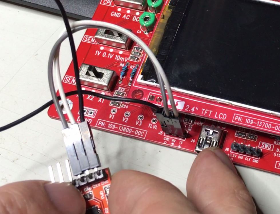 ..
..
DSO138 Case Remix with 9V Battery
thingiverse
This is a remix of https://www.thingiverse.com/thing:2545796 Since i wanted to use a 9V Batterie with the DSO138 i adapted the Case. USB and Powerconnector are not used and therefore removed. For the switches and buttons please use the ones from...
DSO138 Case for Tiny Electronics Lab
thingiverse
... sited as remixed from. works as a case for the ocilloscope. you may need a buck transformer to drop that 24v backbone down to 9v or something depending on how you designed yours. room enough to just throw in a 9v battery if you wanted. ...cheers!
USB Powered DSO138 Oscilloscope Case
thingiverse
This is my version of the DSO138 oscilloscope case that eliminates the 9V power port, and uses the USB for power. By doing this, the oscilloscope becomes ultra portable that can be powered using a USB power bank! To do this, I bought a MT3608...
DSO138 Simple Case
thingiverse
DSO138 Oscilloscope Simple Case -Hardware M3 x 7mm or smaller -Snap on legs (requires light sanding or force) Print Settings Printer: I3 Rafts: No Supports: No Resolution: N/A Infill: 30-50% Notes: Print on flat sides. ... Post-Printing Snap on legs. ..
..
DSO138 Simple Case
thingiverse
This is a case of DSO138 oscilloscope kit. https://youtu.be/UN_BFwLSDpU --------------------------------------------------------------------------------------------------------- 18 May 2018 Add These are downloadable files of Fusion360...
DSO138 Simple Case
thingiverse
The oscilloscope case has an internal board height of 15.5 mm. ...There are also containers for magnets and batteries.
DSO138 oscilloscope case
thingiverse
Simple case for cheap oscilloscope module You`ll need: 1xDSO138 (can be obtained on ebay, aliexpress, etc.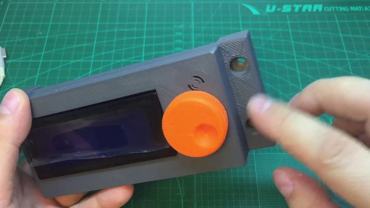 .) 4x M3 screw 9V power supply Printed parts: 1x Top 1x Base 4x Button 3x Switch
DSO138 Mini Case
thingiverse
Case for a DSO138mini (J) Oscilliscope. Complete housing which can be used with the standard test lead plug (white) and with the BNC conncetor. It has openeings for all slide switches and power connection, also small hole for the test signal wire to...
DS0138 / DSO138 oscilloscope case / enclosure
thingiverse
This is a case designed for the cheap DS0138 / DSO138 oscilloscope.
DSO138 Case Remix w/Space for Batteries
thingiverse
Just mixed two designs that I liked in order to get some battery space and the tilt legs for the cool "Fallout" style face plate.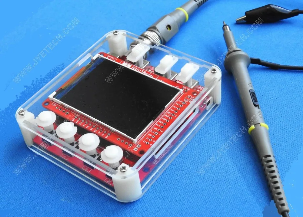 I just trimmed off the slight ridge that was on the original design so it would fit flatly against the front plate.
...
Lithium cell powered DSO138 Oscilloscope Case
thingiverse
This is an 18650 cell powered case for the DSO138 mini oscillocope. Charging is done by a standard TP4056 module. Apply some hot glue to keep it in place. A small boost converter is required to step the voltage to about 8V for the scope. ...
DSO138 Simple Case - No letters
thingiverse
No text version of https://www.thingiverse.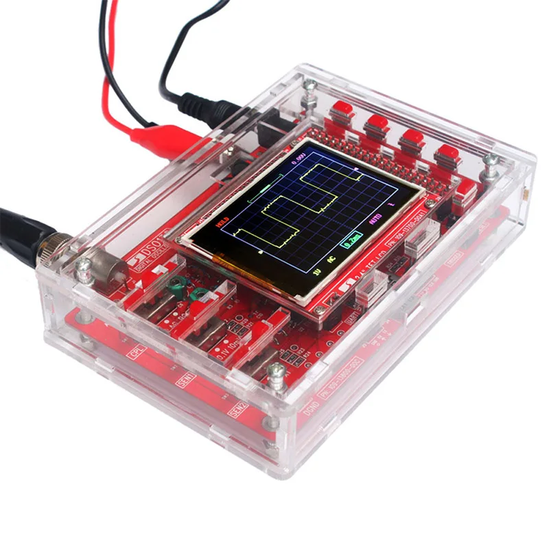 com/thing:2545796
For print settings, check original model.
... I just removed text from upper panel.
Taller Base and modified buttons for DSO138 Simple Case
thingiverse
Probably something different about the DSO138 card. This remix takes the original base and just makes it little taller. Additionally, on the original design, the pushbuttons were a bit tight, and the slider switches seemed too tight also to push...
DSO138 Oscilloscope case with 9V battery and a power switch
thingiverse
This is an adaptation of the case for DSO138 oscilloscope that features a 9V battery and a rocker switch for power (none of that tumbler switch rubbish).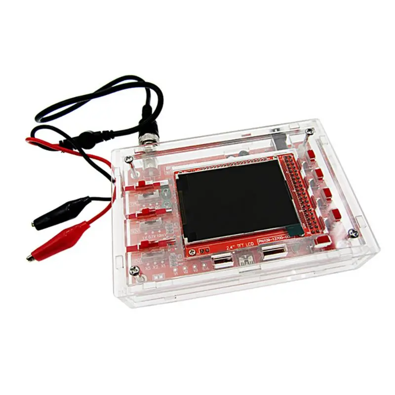 Soldering is pretty simple and is shown on the pictures but feel free to ask questions.
...
Free STL file Case for DSO138-Oszilloscope・3D printing design to download・Cults
hand with ring
Free
Stinkefinger pen holder
Free
Cup of sour cream
Free
Demon hand pencil holder
Free
Starfighter Impeller-Ducted-Fan RC-Plane
Free
Atomium - 3D printed model in stl format and Freecad
Free
FLITZI - RC Aircraft Model
Free
Cafe Clip for large Cafe-Bags
Free
The best files for 3D printers in the Tools category
AMONG US fisherman
0.66 €
3D_Print_Follow_Focus_V2.
 0
0 €15.27
Multi-Color Miniature Laptop
Free
Pumpkin Carving Knife
Free
Lamp holder for Cage modular DSLR
Free
Arrow bookmark(only 15min)
Free
filament holder - suporte para filamento
Free
Ball in a Box
Free
Bestsellers in the Tools category
Filament shielding
2.95 €
Grinder | Grinder
€1.50
Filamentmeter
2,80 €
Ender 3, 3 V2, 3 pro, 3 max, dual 40mm axial fan hot end duct / fang. CR-10, Micro Swiss direct drive and bowden compatible. Printing does not require support
1.68 €
INDICATOR FOR BETTER BED LEVELING FOR ENDER 3 V2
3. 19 €
19 €
NEW GENERATION CAR PHONE HOLDER
2,50 €
FAST PRINT STACKING STORAGE BOXES STACKING CONTAINERS
€1.50 -fifty% 0.75€
Quick print paint bottle holder (6 sizes)
2.88 €
Adjustable archery rig: coil clamp upgrade
5.70 €
INDICATOR FOR BETTER BED LEVELING FOR ENDER 3 PRO
3.19 €
telephone ring holder
0,90 €
Housing FLSUN SR
€8.50
Quick print stackable parts containers / storage boxes
2.88 €
well designed: Hemera fan duct
2.50 €
Ender 3 Briss fang Gen2, red lizard, spider, nf crazy, dragonfly, etc.

€1.87
GEAR AND DRIVE
3.56 €
Do you want to support Cults?
Do you like Cults and want to help us continue our journey on our own ? Please note that we are a small team of 3 people, so it is very easy to support us in maintaining activities and creating future developments. Here are 4 solutions available to everyone:
-
ADVERTISING: Disable the AdBlock banner blocker and click on our banner ads.
-
AFFILIATION: Shop online with our affiliate links here Amazon.
-
DONATIONS: If you want, you can donate via PayPal here.
-
* INVITE YOUR FRIENDS: * Invite your friends, discover the platform and the great 3D files shared by the community!
what is the "toy" capable of? / Tools / iXBT Live
Of course, these cannot be serious models for professionals; but let's figure it out, everything is completely bad there, or not at all ?!
Let's take the popular DSO150 pocket oscilloscope as an example.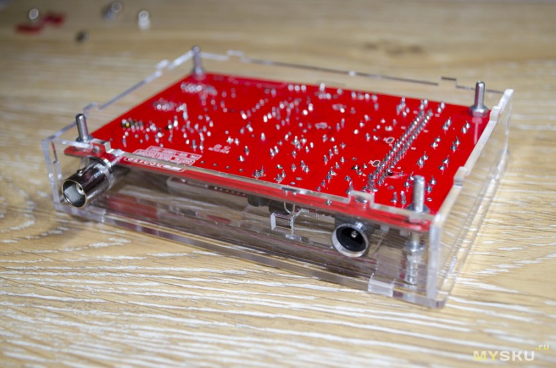 By the way, it is also known under the names DSO Fnirsi 150, DSO Shell and DSO 150 - these are all synonyms.
The image is from the seller's official page (as it turns out later, this is not exactly the same as from the manufacturer's website). All pictures in the review are clickable.
The oscilloscope is sold on Aliexpress in several versions.
One option - fully assembled and "ready to use"; the second option - in the form of body parts, boards and a scattering of parts for soldering; and the third option - body parts and boards with soldered parts. I chose the last option, in which you just need to put everything together correctly without soldering (too lazy, you know).
I bought it all here.
The price of such a kit at the date of the review with delivery to Russia is about $24.
Packaging, kit composition, assembly and appearance of the DSO150 oscilloscope
The oscilloscope arrived in a foam box, conscientiously wrapped with film and tape. This is how it looks after being stripped of the outer covers:
Styrofoam is a good protection against troubles on the way; nothing inside was damaged.
The box itself contained the following set of parts for assembly:
Assembly did not go smoothly.
I really didn't want to fit the encoder handle on its axis. I had to use brute physical force (this helped to dress her, although not quite to the end; it was scary to break something).
Perhaps a better option would be to use a soldering or cosmetic hair dryer to heat up the shaft and handle (but be careful not to melt the plastic parts).
In addition, it was not possible to fit the top cover and bottom so precisely that there was no gap between them at all. True, the remaining gap of half a millimeter can even be called decorative.
Let's look at the build result.
Top view:
Bottom view:
Two diagonal views:
Bottom side view:
View from the top side:
Here (on the top end) there is an input switching slider (closed / open / ground), a 1 kHz calibration voltage flat contact, and, in fact, a BNC connector for signaling.
In general, the appearance of the oscilloscope turned out to be quite decent, and does not particularly resemble a “toy” or a training copy (like its historical predecessor DSO138 in a transparent case or even in a frameless form).
The case is also well sealed against the penetration of small external objects and dirt (unlike, for example, DSO188).
But what is not good is the need for external power supply (there is no built-in battery). True, there is still free space inside the oscilloscope to place the battery and the necessary “strapping” there, but this is not for lazy people like me. A discussion of how to install internal power is on the forum of the official manufacturer (JYE Tech).
DSO150 oscilloscope printed circuit boards and circuitry
Finally, we have come to the electronic "stuffing" of our oscilloscope.
This filling consists of two boards: analog and digital.
Analog board - small. but very full of components:
Here I am glad that the marking of all elements is left readable, and even duplicated by inscriptions on the board. It happens that some particularly unscrupulous Chinese manufacturers, on the contrary, carefully overwrite the markings in order to make it difficult to repair products. But this is not the case, fortunately!
Moreover, schematic diagrams can also be downloaded from the official page of the oscilloscope on the manufacturer's website (at the bottom of the page, in the "Documents" section). In general, this can already be equated to a miracle !!!
The main element on the board is a TL084C quad opamp with FET inputs. He is responsible for receiving and amplifying the signal.
Two analog switches provide gain scaling: HC4053 and HC4051.
All the microcircuits listed above require a bipolar power supply, and the device is powered by a unipolar one. Accordingly, the ICL7660 converter creates a negative polarity for the internal power supply, and stabilizes the power supply 78L05 (+5 V) and 79L05 (-5 V).
The green trimmers on the top of the board are responsible for adjusting the input capacitance (required for the correct display of signal edges). Instructions for setting up are in the attached paper document (you need to set up, of course, before installing the boards in the case; or in the case, but without the top end cap).
Now let's examine the digital board, first - the view from the side of the screen:
Here - the encoder knob, buttons and screen. The screen cable under it is soldered directly to the board. This will make it difficult to change the screen if you "bang" it. True, after assembling the oscilloscope, it will be quite difficult to do this, because. the screen is located in the recess. But accuracy in handling is not canceled.
The screen is not dimmable, but its brightness is set to a moderate level sufficient for comfortable viewing in typical applications.
Screen viewing angles are different vertically and horizontally.
The horizontal viewing angle is not wide, even with small turns to the right and left the screen becomes noticeably pale.
When turning up and down, on the contrary, the image remains bright and contrasting even at large turns.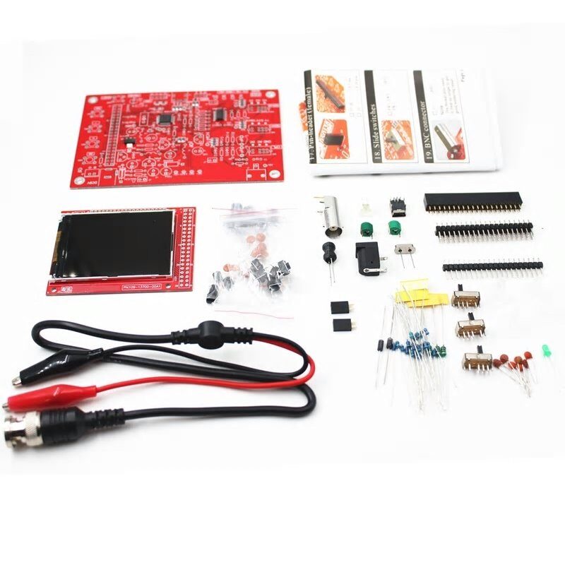
The view of the digital board from the side of the elements is much more interesting:
Here, first, let's pay attention to an important organizational point: in the white frame located in the lower left corner, there should be a board number, but it is not there!
In accordance with the manufacturer's instructions "How to distinguish a non-original oscilloscope from the original" (link), we conclude that this copy is not original.
What follows from this? It follows that its firmware is unlikely to be updated. In the best case, the new firmware simply will not be installed (the manufacturer will not give a code for installing it), and in the worst case, the oscilloscope may “brick”. Is it possible to live with the firmware as it is - let's figure it out.
Let's get back to the board.
Here we see the "heart" of the oscilloscope - analog-to-digital processor STM32F103C8T6.
Next to it is an 8 MHz quartz; but the processor has its own frequency multiplier and runs at 72 MHz. This is not much, but at a low frequency and energy consumption is less.
The processor is made according to the "all-in-one" principle: RAM and ROM are also in the processor. It also generates an image to be sent to the display.
In addition to the processor, the board has two more "mikruh": flash memory with a serial interface and a 3.3 V linear regulator that provides power to the processor.
To finally clarify the situation with the software (firmware) version, let's look at the screenshot at the time of loading the oscilloscope:
Thus, the oscilloscope works under firmware version 062. This version is not the latest, but it is quite well-developed and should not surprise you with strong glitches.
Testing the DSO150 oscilloscope
We figured out the mechanics and circuit, let's move on to practical testing. The FY6800 generator was used for testing.
Let's start with the elementary and standard: sine, 1 kHz, 5 V peak (you can't think of a standard one!):
We first pay attention to the many parameters measured by the oscilloscope in real time, right along the signal path.
In addition to the measurement results, the oscilloscope shows its own operating modes (above the waveform and below it).
If the measurement data interferes with the waveform, it can be removed from the screen.
And now let's check the measurement accuracy.
The oscilloscope showed a voltage swing (Vpp) of 5.15 V. This is a good result, since it fits within the stated error of 5%. True, with a decrease in the amplitude of the signal, the accuracy also decreases, but this corresponds to the theory of the issue.
Now let's look at the frequency. The oscilloscope showed 973.303 Hz. For measuring frequency, such accuracy is simply not good enough.
Checking the frequency measurement with a different time scale showed a much more decent result:
Here the oscilloscope measured the frequency exactly: 1 kHz.
Most likely, the device calculates the frequency primitively, according to the number of times the signal crosses the trigger level for a period equal to the buffer filling. The more periods fit into the buffer, the more accurate the frequency measurement is.
Let's move on.
Testing the bandwidth at minus 3 dB showed a result approximately corresponding to the declared in the parameters: about 220 kHz.
Now we feed a 20 kHz rectangle and check the fronts:
In general, the fronts of the “rectangle” can be assessed as good. But there is also an interesting feature: the negative front is steeper than the positive one; which has a fairly smooth "rounding" at the top.
Similar effects will be observed on other oscillograms of the "classic" series:
Now let's move from theory to practice and look at a couple of real oscillograms.
As a test object, a switching power supply was chosen, giving voltages of + 5 and +12 V with an output current of 3 A for +5 V output and 2 A for +12 V output. voltage rectifier +5 V.
Option 1, power supply without load:
Option 2, with a load of 1 A at +5 V output:
Oscillograms can be used to estimate the frequency of operation of the switching power supply converter (a little above 50 kHz) and the magnitude of the forward and reverse pulses .
It is useless to look at the signal frequency according to the measurement readings of the oscilloscope itself for signals of such a complex shape - it can show anything (and quite legally).
As a result of this chapter, it must be said that electrical processes with a frequency of about 50 kHz are the limit when you can really track the waveform using this oscilloscope. For higher frequencies, there will be too few samples per signal period to judge its real shape.
Strobo effect
Users of digital oscilloscopes are probably already aware of this interesting effect. But for amateurs and professionals who have so far used only analog “tube” oscilloscopes, this may be news. :)
By the way, analog oscilloscopes are not an anachronism, they are still successfully produced and used. But, of course, the lack of mathematical processing in them, as well as their large weight and dimensions, do not contribute to their popularity.
I will start approaching the problem from afar.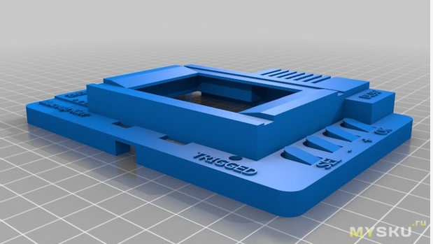 In Wikipedia, in the article "Oscilloscope", there is an interesting passage about the shortcomings of digital oscilloscopes (underlined):
This problem (displaying non-existent signals instead of real ones) occurs due to the stroboscopic effect.
Stroboscopic effects occur when the number of signal samples per period becomes too small.
According to the classical Kotelnikov's theorem for radio engineering, any signal can be absolutely accurately restored if its sampling frequency is at least twice the upper frequency in the signal spectrum.
But this is valid, relatively speaking, for signals of infinite length and after processing by appropriate algorithms, and not in real time.
And in real time, the signal "loses shape" so seriously that it becomes completely different from itself.
So, for example, our oscilloscope shows a sinusoid with a frequency of 246 kHz:
The observer sees a non-existent amplitude-modulated signal on the screen.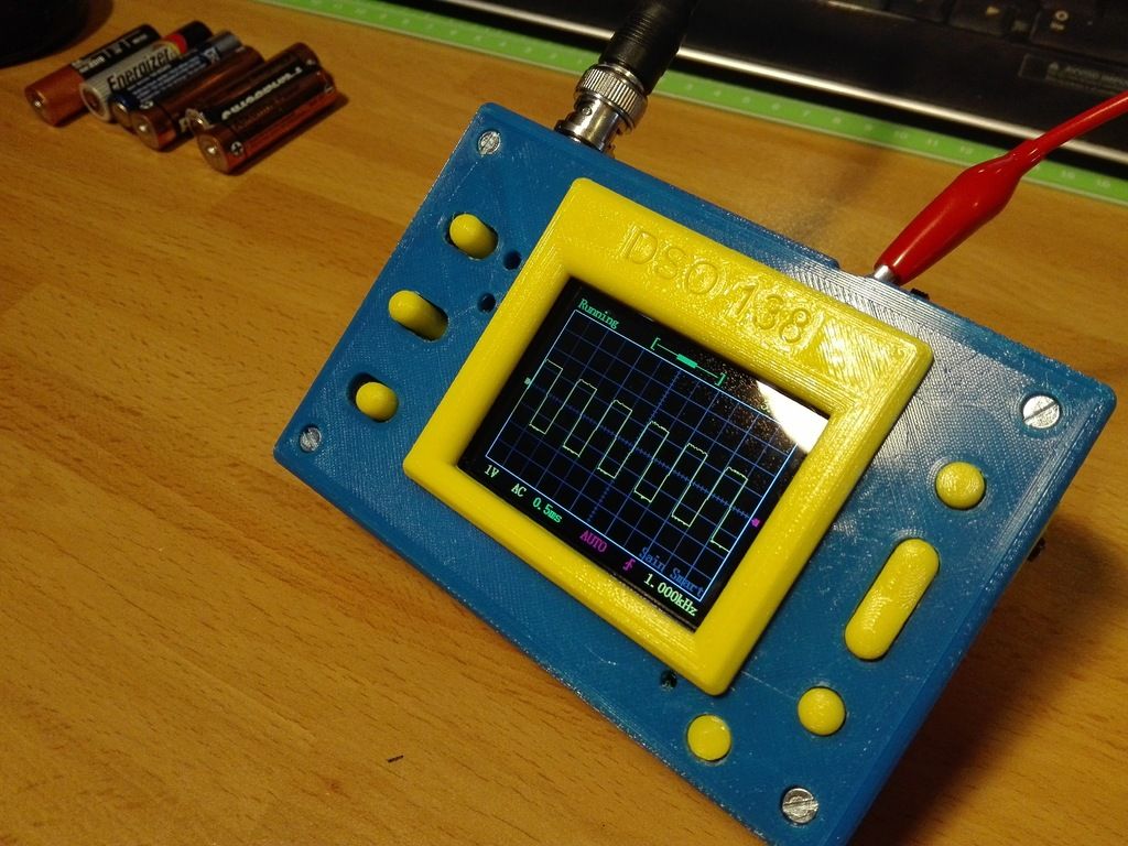 In fact, a pure sine wave is fed to the oscilloscope.
Sometimes even experienced reviewers write that at a high frequency, an oscilloscope shows a signal with a corrupted shape, jumping amplitude, etc. In fact, such a mapping of the signal can be quite legal from a physical and even from a geometric point of view.
Since switching the time scale on the oscilloscope also changes its sampling rate, the user can see these effects even at fairly low frequencies.
For example, the following waveform was taken with a square wave frequency of 124 kHz; but due to the fact that the sampling frequency at a scale of 0.2 ms / division decreased to 50 kHz, the signal on the screen degenerated into a rectangle with a frequency of 1 kHz:
It will seem to the observer. that he sees a rectangular signal with a frequency of 1 kHz; and only the fronts that are unnaturally tightened for such a frequency will be a hint that "something is wrong here."
The existence of this effect must be taken into account when working with digital oscilloscopes (ie, choosing the right horizontal sweep parameters).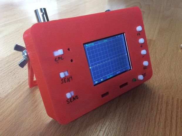
This effect can also be used to advantage: there are special stroboscopic oscilloscopes for studying periodic processes in the microwave, but these are far from “general civil” devices.
Conclusion
The oscilloscope tested is one of the cheapest ones, commonly referred to as "toys" or "display meters".
However, it can be used for serious purposes, if you do not set impossible tasks for it.
For example, for testing and tuning class D amplifiers, it is not suitable: there the PWM pulse frequency starts from 400 kHz.
On the other hand, there are almost no obstacles for working with “ordinary” amplifiers (class A or AB); except that it may not show the self-excitation of the amplifier if it happened at a high frequency.
It can also be used to work with switching power supplies with a PWM frequency of up to 50 kHz (and this, however, is not always the case; sometimes even in typical power bank controllers, the frequency can be up to 100 kHz).