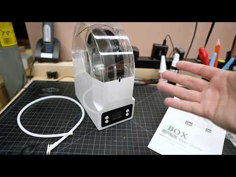
Dry box 3d printer
Filament dryboxes and alternative spool holders - not only for MMU2S
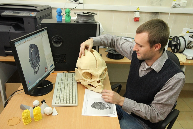
Nearly all Original Prusa i3 3D printers have a spool of filament placed in the original holder on the frame. This solution is trouble-free, practical, functional and mobile. However, if you want to print from special materials, which are hygroscopic, you need to keep the filament dry also during printing – that’s what silica gel is for. We present several solutions for this case.
What is a drybox?
A drybox keeps the filament dry during printing and also protects the filament from dust. A 3D printer with our Multi-Material Upgrade not only allows you to print from filaments of different colors but also gives you the opportunity to print with different kinds of materials. A practical example: printing water-soluble supports. The usual approach is to print supports with the same filament used for printing of the model itself. Once it’s done, it is necessary to remove the supports manually – using force. This results in visible marks left on the print. In some cases, the supports may be difficult to access and may even be impossible to remove. There must be a small gap (typically 0.1 mm) between supports and the print. Therefore, the surface under the supports is not perfectly smooth. On the other hand, soluble supports can be printed without spacing and dissolved in water. The print surface is therefore much nicer.
On the picture below, you can see the different surfaces above supports. From left: without supports, with normal supports, with soluble supports.
Table of contents
- Drybox for one filament + four filaments without cover (for MMU2S enclosure)
- Dryboxes on a wall for any number of filaments
- Samla Drybox for three filaments (for MMU2S enclosure)
- 2x Samla Drybox for up to six filaments
- Community solutions and ideas
Drybox for one filament + four filaments without cover (for MMU2S enclosure)
When printing soluble material with the MMU2S, the soluble filament should be in the fifth filament slot (as default). That is why the drybox is adapted to the location on the right. The modular filament holder is a part of the construction of the MMU2S Printer Enclosure V2. We created an alternative part that works as a cover / drybox for the fifth filament.
Benefits of our drybox
- filament is protected from dust
- filament is in a dry environment thanks to silica gel
- simple and functional oval filament outlet which is covered by a piece of foil
- easy to load filament
- easy replacement of silica gel thanks to the tray on the bottom of the box
Parts and fasteners
- printed plastic parts (preferably PLA material) – make sure you chose the right parts depending on whether you want to place the humidity sensor in the box or not
- 2x M3x30 screw
- 3x M3x10 screw
- 1x M3x5 screw
- 4pcs of 608RS bearings (from original spool holders)
- 2pcs aluminum tube diameter 7.8 mm (from original spool holders)
- plastic film from Prusament coil (or similar quality film 0.
 1mm thick
 - humidity sensor – optional
- silica gel
Building the box
- Shorten the aluminum tubes from the original spool holders to 100 mm length.
- Secure the box closing knob with the M3x10 screw. Make sure that the pin on the bottom of the box fits into the groove in the knob.
- Cut the same size foil from a Prusament bag so it fits the frame.
- Insert the foil and frame into the box and secure them from outside with two M3x10 screws.
- Use a sharp scalpel to cut the foil in the middle of the groove.
- Screw the M3x5 screw into the lid.
- Attach both halves together with two M3x30 screws.
- Place the tray on the bottom of the box and fill it with silica gel.
- Place bearings on the axes and snap them into the box.
- Push the humidity sensor into the box.
During testing, the air humidity was kept below 20% in the box at an ambient air humidity of approximately 45%.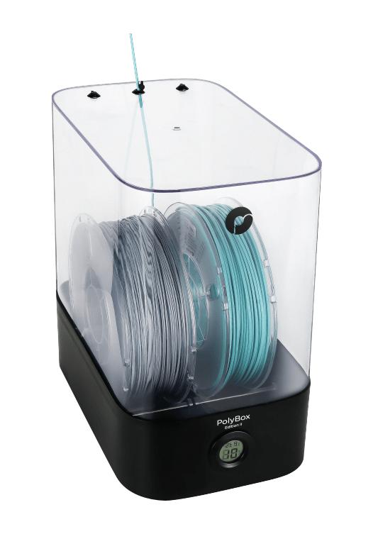
Dryboxes on a wall (for any number of filaments)
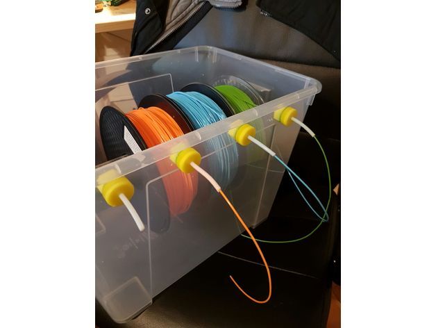
This drybox is of a similar design as the first one. However, this version can be secured onto a wall. You can use any number of dryboxes. When used with the MMU2S, it is recommended to attach the filament buffer under the dryboxes onto the wall, but you can also try printing without the filament buffer. If you do not have a multimaterial upgrade, you can use multiple boxes as storage space and have several materials at hand, so they can be switched quickly and easily.
The assembly of these dryboxes is similar to the previously described design. This versions, however, have the filament outlet at a different location and it also has mounting holes. Use these buffer mounts when mounting the buffer onto a wall. Be sure to select the right model to print depending on whether you want to use the humidity sensor. We recommend using PLA for printing – we used Prusament PLA Prusa Galaxy Black.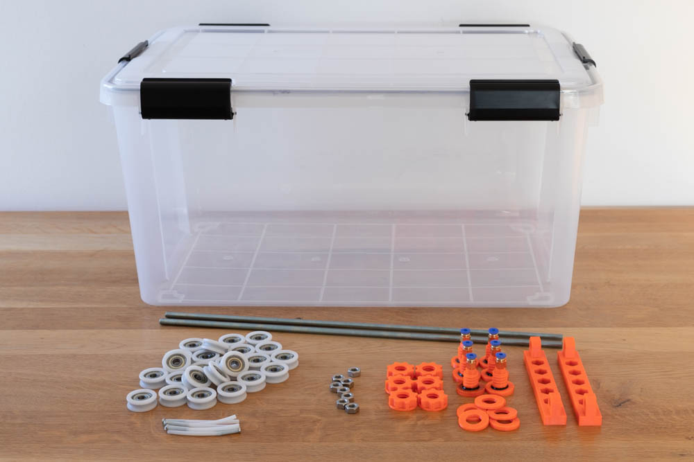
Samla Drybox for three filaments for MMU2S box
A slightly less refined design, yet a very simple and functional solution is a drybox built made using Ikea Samla boxes. The box can easily fit two filaments. If you print the middle holder, the third filament will also fit inside.
Material for the 3-filament version
- printed plastic parts of sliders and middle filament holder
- filament buffer holders
- printed lid clips
- 1x IKEA Samla box with lid 39x28x28 cm / 22l
- 12x 608RS bearings (from original spool holders)
- 4x 7.8 mm aluminum tubes (from original spool holders)
- 2x original spool holder
- 6x M3x18 screw
- 4x M3x10 screw
- 10x M3 nuts
- 4x 3,5×20 wood screw or similar (mounting box to the table)
- 2x 3,5×35 wood screw (filament buffer mounting)
- humidity sensor – optional
- silica gel
Assembly instructions
- Place the slider on the box and mark the holes on the box where the sliders will be attached with screws.
- Drill the holes in the indicated locations with a 4 mm drill bit.
- Place the inner slider part on the box and align the part with the drilled holes.
- Mark the oval holes in the box slider with a marker.
- Create oval holes by drilling a hole next to hole with 5mm diameter drill bit and then cutting the residue with a sharp knife. ATTENTION – the box material is fragile.
- Attach the sliders onto the box (M3x18 screws).
- Unscrew the filament buffer and replace the middle holders with new ones.
- Place the drybox in the center of the top lid and screw it with four screws. We recommend pre-drilling holes in the box.
- PTFE tubes should be approx. 0.5 cm from the drybox.
- Place the two original spool holders in the box and fill them with silica gel.
- Place the humidity sensor inside the box.
- Assemble the printed middle filament holder and place it in the center of the box.
- Pass the filaments through the sliders and secure the lid with the printed clips
During testing, the air humidity was kept below 20% in the box at an ambient air humidity of approximately 45%.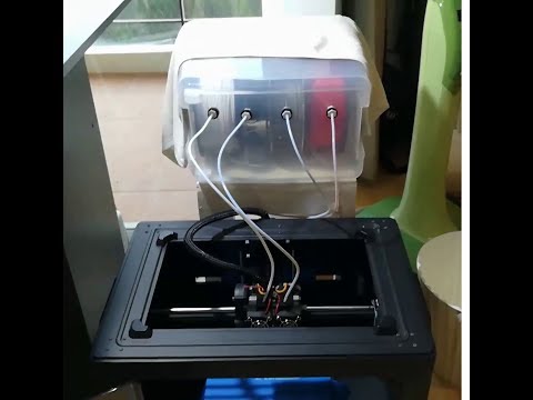
2x Samla Drybox for up to six filaments
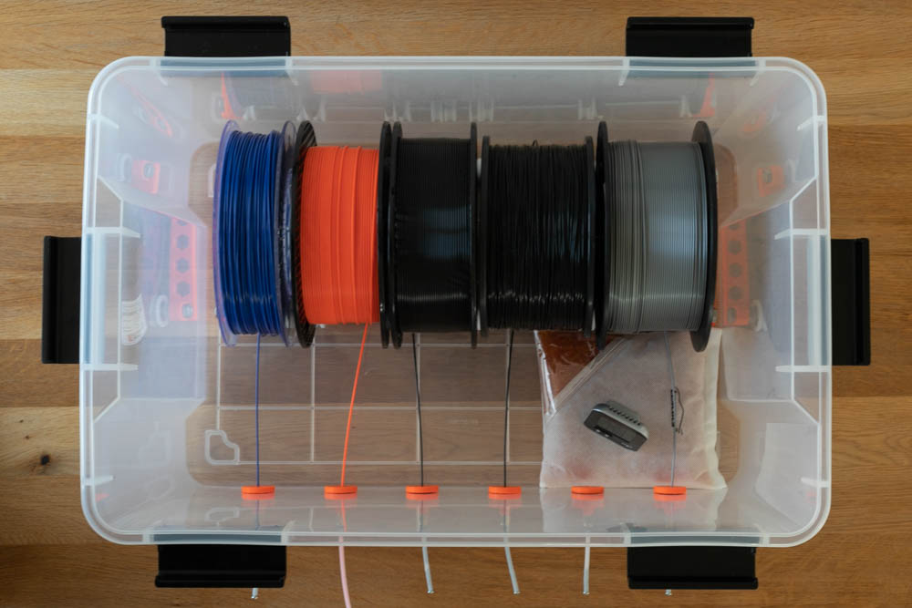
The Samla Drybox design can be used without Prusa Printer Enclosure V2 – the printer with the MMU2S upgrade can be placed on a table (see the picture below). In such a case, it is even possible to place two boxes on top of each other. Then there is enough place up to six filaments. According to our tests, this solution can be used without a filament buffer. Place the boxes behind the printer so that the PTFE tubes from the MMU2S unit end close to the drybox sliders. Building material is identical to the previous solution, only the amount of material used is doubled.
Silica gel can be re-dried in an oven and then reused.
Community solutions and ideas
Original Prusa printer owners are usually very creative people and true makers, who often design and produce their own printer accessories. At PrusaPrinters.org, there’s plenty of various add-ons, tweaks, and mods. However, keep in mind that not every “upgrade” brings only benefits. Non-original filament setup can, in some cases, negatively affect print quality and reliability. Always assemble and test your 3D printer as stated in original instructions, before you start to experiment with mods.
Do you have your own original solution you would like to show? Share your models and prints on PrusaPrinters.org, on our forum, Twitter, Instagram or Pinterest and we will add them to the gallery below.
Happy printing!
Instruction: DIY filament dry box
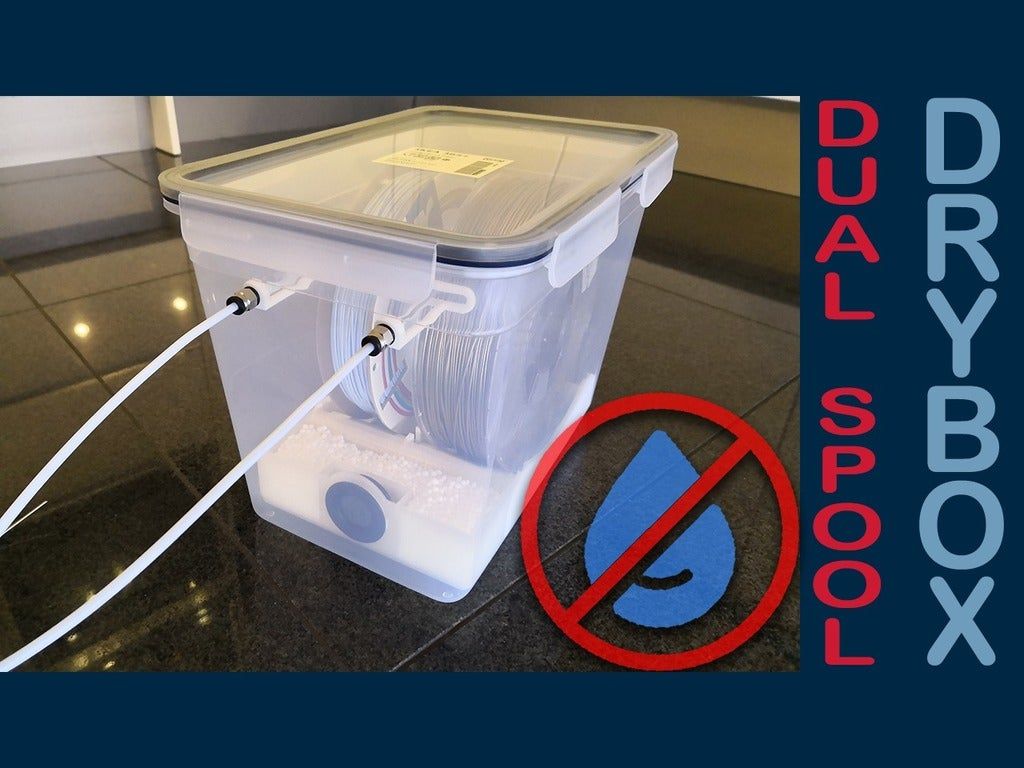
Here you will find the instructions to build a filament dry box that is much more than just an airtight storage box. Everybody who prints knows following situation, the filament spools are packed airtight in plastic bags and distributed throughout the room and every change of the filament on the 3D printer is a complicated, time-consuming procedure. Then the filament roll stays on the 3D printer far too long because it was forgotten to pack the roll airtight again. As a result, the filament draws moisture and becomes dusty, both of which are bad for the quality of the next 3D prints.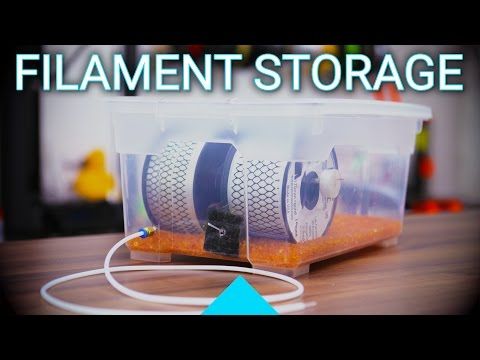
The DIY filament box solves exactly this problem, because the filament spools stored in the self-made filament dry box remain airtight and dust-free – even if they are currently used to 3D print something. Once built, up to 6 filament spools fit inside and you no longer have to worry about filament storage.
The article contains affiliate links / advertising links, these are marked with an asterisk (*).
Why should I build a filament dry box?
3D printing filaments absorb water over time, which leads to ugly prints and printing errors. That is why it is important to keep your filament rolls airtight, ideally with the addition of a desiccant (silica gel). With these instructions you can convert an airtight storage box so that you can print directly from it. Save yourself the annoying unpacking and packing of the filament spools. With a few simple purchased parts and the 3D print files from the shop you get the optimal addition to your 3D printer.
Advantages of the filament dry box
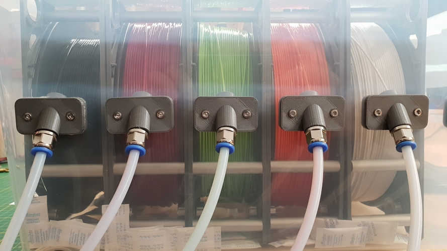
The great advantage of the filament box over other solutions is the simultaneous storage and readiness for printing with up to 6 filament spools. Simply pull the sealing plug off the PTFE tube, pull out the filament and feed it to your 3D printer. Printing with dry and dust-free filament has never been easier.
In addition to the support of 1.75 mm and 2.85 mm filament, two different variants are available for sealing the PTFE tubes. This means that long filament guides – right up to the printer – can be rolled up and stored neatly and beautifully.
Variant A: Simple plugVariant B: Plug is fixed at the filament boxIn principle, it is only a matter of preventing “spaghetti” with long PTFE tubes. The advantage of long filament guides, as shown in variant B, is that almost no excess filament has to be shortened when changing filaments, without laborious manual rolling of the filament.
- Variant A: Simply a plug to seal the tubes.
- Variant B: For the sake of order, a long PFTE tube (e.g. up to your 3D printer) can be rolled up and inserted into the plug that is integrated in the filament outlet.
Regardless of which plug solution is used, there is a reservoir in both where 1 – 2 cm of filament protrudes from the PTFE tube, see the cross-sections through the two variants below. The filament is colored blue, the PTFE tube in pale orange.
After opening the PTFE tube there is always 1-2 cm of filament available to simply pull it out and feed it to the 3D printer.
Variant A: Simple plugVariant B: Plug is fixed at the filament boxAll advantages of the new, improved airtight filament dry box compared to the old version are summarized here in this article.
Instructions: Build a DIY filament box
The instructions are divided into individual steps. To provide a short overview: the safety instructions, the required 3D printing parts, purchased parts and tools are summarized right at the beginning. At the end of the assembly instructions you will find the operation manual.
Safety Guidelines
Safety first! Read and follow the assembly instructions and the operation manual!
Read the entire instructions and operation manual carefully and adhere to the instructions and safety guidelines. If anything is unclear, simply contact support ([email protected]). In the 3D print files for this project, the instructions and operation manual are also attached as PDF, keep it because you may need it later. A one-page quick guide is also included in the files with a link to this page – you will always find the latest version of the instructions and the operation manual here. If you are giving the project to someone else, then print out the instructions, operation manual and, above all, the safety instructions and pass them on with the project.
Before you start the project, also check whether the project meets the safety regulations of your respective country.
Safety instructions for this 3D printing project
This symbol indicates a hazard that will result in serious injury or death if the instruction is not followed.This symbol indicates a hazard that could result in serious injury or death if the instruction is not followed.This symbol indicates a danger which can lead to minor injuries if the instruction is not followed.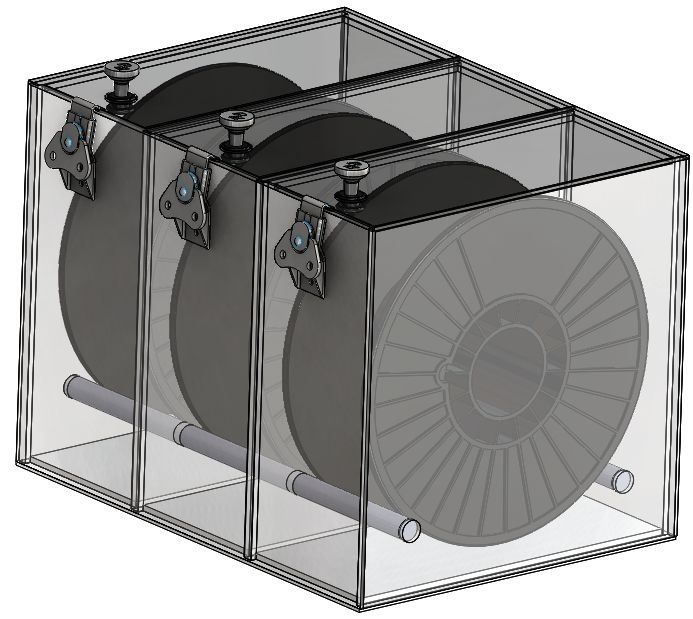 This symbol indicates possible damage to the project or the environment if the instruction is not followed.
Safety instructions for this 3D printing project
Never lock living beings (children, animals) in the box! Danger of suffocation, danger to life! Only for storing commercially available filament!
Keep the filament box safe and out of the reach of children and animals, the filament dry box is not a toy!
Do not leave the 3D printer unattended while printing! If the printing is interrupted or the 3D printer makes unusual noises, switch off the 3D printer immediately, check the filament box and the filament feed!
Also read through, follow and keep the operation manuals and safety instructions for the purchased parts!
Attention for all purchased parts: Before assembling, check whether they meet the safety regulations in your country and whether the dimensions, function and stability are fine. Repeat this safety check at regular intervals and before using the project.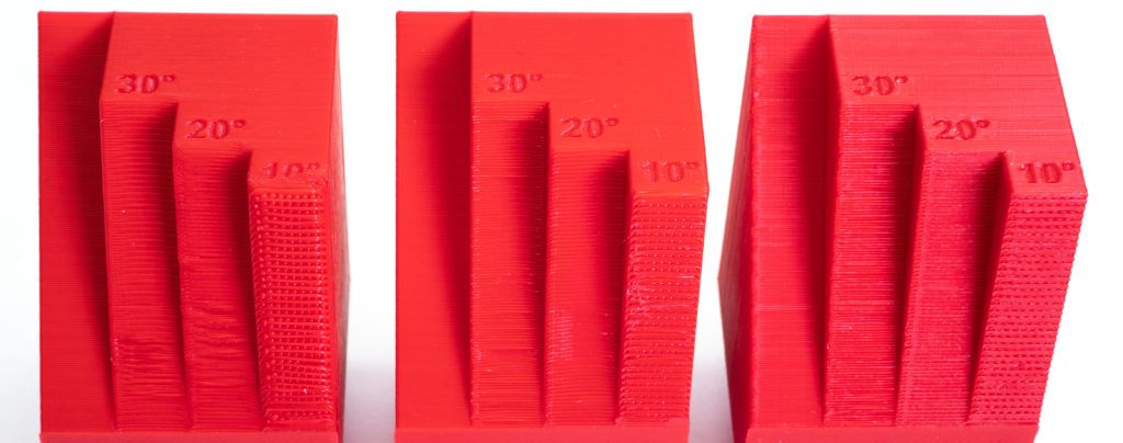 If a part is damaged or unsuitable, do not continue to use the project until the affected part has be
Attention for all self-printed parts: Due to incorrectly set printing parameters, poor material, incorrect material selection, poor layer adhesion and other reasons, these can sometimes not meet the requirements needed on them and thus break, fail or their functionality cannot be guaranteed. In the event of a break, the parts can splinter and the fracture surface leave sharp edges. Take particular care when replacing these parts, there is a risk of cuts! Check 3D printed parts for cracks, stability and functionality at regular intervals and before using the project. If a part is damaged or unsuitable, do not continue to use the project until the broken part has been replaced with a new, improved part.
Always place the filament dry box horizontally and at a stable, safe location.
When printing parts, sharp edges can occur (usually on the first layer), there is a risk of cuts! These edges have to be ground down in order to deburr them.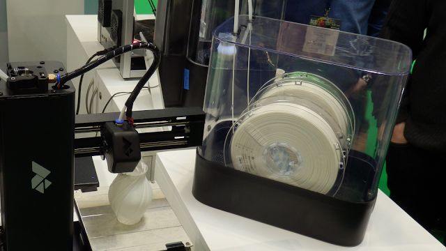
3D printed parts
Buy the 3D print files in the shop
The files of the required 3D print parts are available here in the shop
This is a purely digital product, you get all the files you need to print in a ZIP-file. The STL-files for the required components, for the versions for 1.75 mm and 2.85 mm filament, as well as for the different PTFE tubes (OD4 ID2, OD4 ID3 and OD5 ID3) are included.
- 000100_Rod_Mount
- 000200_Pulley
- 000300_Spacer
- 000400_Tool_Bearing_Press_In
- 000500_Tool_Bearing_Press_Out
- 000600_Tool_Bearing_Press_Counter
- 000700_Filament_Outlet_175_OD4
- 000800_Nut
- 000900_Plug_OD4
- 001000_Clamping_Ring
- 001100_Clamping_Plug_OD4
- 001200_SilicaGel_Carrier
- 001300_SilicaGel_Plate
- 001400_Filament_Outlet_175_OD5
- 001500_Filament_Outlet_285_OD4
- 001600_Filament_Outlet_285_OD5
- 001700_Plug_OD5
- 001800_Clamping_Plug_OD5
The largest 3D printed part of this project (SilicaGel_Carrier) requires a base area (X, Y) of 166 x 52 mm, the highest part (Plug) is 39 mm high (Z). Any 3D printer with a build volume (X, Y, Z) of at least 170 x 170 x 40 mm is suitable for this project.
3D print settings
For the parts: 000100_Rod_Mount, 001200_SilicaGel_Carrier and 001300_SilicaGel_Plate:
- Layer height 0.2 mm and 20% infill (rectangular)
For all other parts:
- Layer height 0.2 mm and 100% infill (rectangular)
The following settings have proven themselves for the used PETG*:
- Nozzle temperature: 250°C (First layer: 240°C)
- Bed temperature: 90°C (First layer: 85°C)
- Perimeter speed: 45 mm/s (First layer: 10 mm/s)
- External and short perimeter speed: 25 mm/s (First layer: 10 mm/s)
- Infill speed: 80 mm/s (First layer: 10 mm/s)
- Top solid infill speed: 40 mm/s
Used 3D printing filament and 3D printer
For this instruction Prusament PETG Prusa Orange* Filament was printed on a Prusa i3 MK3s* 3D printer with a standard 0.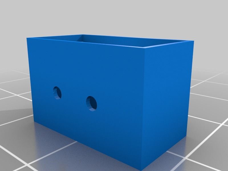 4 mm nozzle.
Approximately 265 g PETG filament* is needed for all required parts of one filament box. At a price per kilo of EUR 29.90, this is around EUR 7.90 in material costs for one filament box. The total 3D printing time for all required components is approx. 28 hours. To calculate the total 3D printing time, all printing times are added up, whereby the total number of pieces of a component is always printed at once.
Because of the higher stability and the low warpage, I recommend a PETG* filament. The parts could be also be printed with ABS or ASA*, but these place higher demands on the 3D printer and operator. The widespread material PLA* is not recommended because technically more demanding parts are not stable enough due to the more brittle nature and the lower layer adhesion of this material. In particular, the clamping jaws of the Filament_Outlet can fail, see the safety information.
It is essential to print the Filament_Outlets with 100% infill and a mechanically resilient material (PETG, ABS, ASA, etc.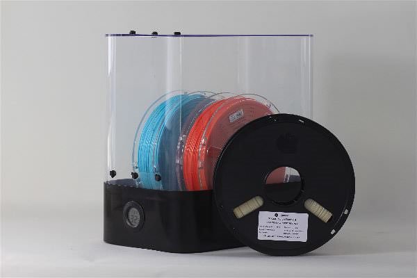 ). Tests of an external tester have shown that these components, printed with PLA, can break when they are clamped or after a while after assembly.
Bill of materials: Needed purchased parts for the filament dry box
- 1 pc 50l air-tight box (Amazon Germany)* (approx. 25 EUR / pc) – for Amazon US see the Qt62.8 air-tight box (US)* or the Qt46.6 air-tight box (US)*
- 24 pcs Ball bearings 608 (Amazon Germany)* (approx. 10 EUR / 20 pcs) – for Amazon US see these ball bearings 608 (US)*
- 1 m Threaded rod M8* (approx. 15 EUR / 5 m)
- 12 pcs Nut M8 DIN934* (approx. 9 EUR / 50 pcs)
- 1-6 m PTFE tube OD4 ID3* (approx. 6 EUR / m) – alternatives possible
- 1 pc Silica gel bag* (approx. 7 EUR) – alternatives possible
- 4 pcs Cylinderhead screw M3x14 DIN912* (approx. 7 EUR / 50 pcs)
- 4 pcs Nut M3 DIN934* (approx. 5 EUR / 50 pcs)
The dimensions of the air tight boxes from Amazon US – Qt62.8 and Qt46.6 – are close to the German boxes, but not identical.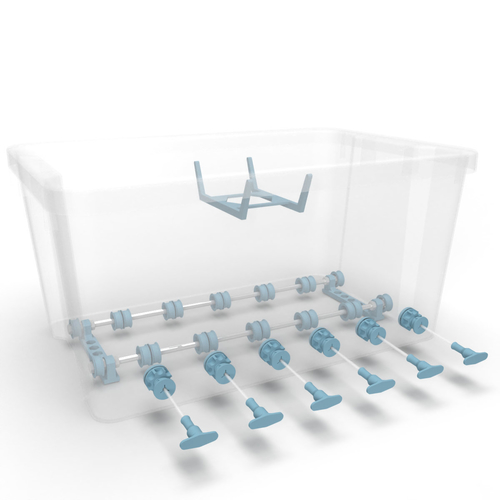 Please check your filament spool dimensions, adapt the length of the threaded rods, and the distance and amount of the filament outlets.
The total costs of the purchased parts come to approx. 67 EUR. For the calculation only the costs for the required parts for one filament box were added together.
Alternative purchased parts
Threaded rod, screws and nuts: They are usually much cheaper in hardware stores and can be bought there in the required number of pieces.
PTFE tubes: Besides the OD4 ID3 (outer diameter 4 mm and inner diameter 3 mm) it is also possible to build the filament box with OD4 ID2 and OD5 ID3 tubes. Use tubes with an inner diameter of 3 mm if the box is built for 2.85 mm filament. But I also recommend the ID3 tubes in variant B with long filament guides, as the friction in the ID2 tubes on longer distances is higher, especially with rough filament (matt colors). Depending on the version you are going to build more or less tube length is needed.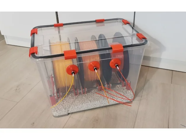
Silica Gel: If you got other silica gel bags or if you prefer loose silica gel, then download the free 3D print files of the silica gel box. With this free addon loose silica gel can be used in the filament dry box.
Airtight box: Of course, other airtight boxes can also be used, but please check the dimensions to ensure that the filament rolls have enough space in them. The length of the threaded rods must then be adapted to the respective width of the alternative box.
Additional parts
To check the humidity level in the box, a hygrometer* can be bought for about 14 EUR. The measuring range for the humidity starts with these hobby devices only at 10% to 20%, that means even if the measuring device shows these values and not 0% everything is fine.
Required tools
- Cordless screwdriver*
- Allen key set* (M3 key 2,5 mm)
- Wrench set small* (M3 wrench size 5.5 mm)
- Wrench set basic* (M8 wrench size 13 mm)
- Wood drill bit 2 mm* und Wood drill bit 4 mm* (wood drill bits cut best through the plastic of the box)
- Step drill bit* (including 16 mm step)
- Hacksaw* (for cutting the threaded rod)
- Metal file* (for deburring the thread cuts)
- Marker pen*
- Box cutter*
- Scissors*
- Double-sided tape*
Step 1: Building the filament roll storage
Required purchased parts
- 24 pcs ball bearings 608* (approx.
 10 Eur / 20 pcs)
 - 1 m threaded rod M8* (approx. 7 EUR)
- 12 pcs Nut M8 DIN934* (approx. 9 EUR / 50 pcs)
Use a hacksaw to saw the threaded rod into 2 pieces, each 485 mm long.
Clamp the threaded rods securely before sawing, wear protective goggles and gloves when cutting.
Beware of sharp metal grades! Deburr the threaded rods with a file after sawing.
Required 3D printed parts
- 2 pcs 000100_Rod_Mount
Layer height 0.2 mm and 20% infill (rectangular)
- 24 pcs 000200_Pulley
- 10 pcs 000300_Spacer
Layer height 0.2 mm and 100% infill (rectangular)
Pro tip: first print only one pulley and one spacer, then press in a bearing and thread the spacer onto the threaded rod. If this works the remaining parts can be printed. If the pulley or the spacer is too tight, the parts can be enlarged a little in the slicer (scale function) until the bearing sits well, or the spacer can move freely.
To press the ball bearings into the pulleys, use the tools provided in the 3D print files.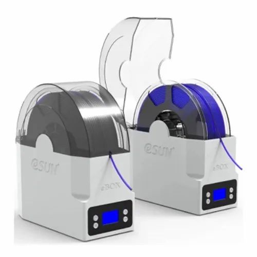 This makes it much easier to press in the bearings and to press them out again if necessary.
Use the included 3D printed tools for easier assembly and disassembly of the ball bearings in the rollers.
- 1 pc 000400_Tool_Bearing_Press_In
- 1 pc 000500_Tool_Bearing_Press_Out
- 1 pc 000600_Tool_Bearing_Press_Counter
Layer height 0.2 mm and 100% infill (rectangular)
Pressing the 608 ball bearings into the pulleys for the filament box
Prepare one 608 ball bearing, one 3D printed pulley and the press-in tool.
Insert the ball bearing on the side of the pulley with the larger opening.
Position the press-in tool and press firmly until the ball bearing is completely pressed against the lower edge in the roller.
If the ball bearing has been pressed in correctly, it will sit parallel to the pulley and approx. 2 mm deep from the pulley surface.
The ball bearings must sit securely and firmly, as well as parallel and not tilted in the pulleys! Important so that the filament rolls do not block later!
Now prepare all remaining pulleys according to the same scheme.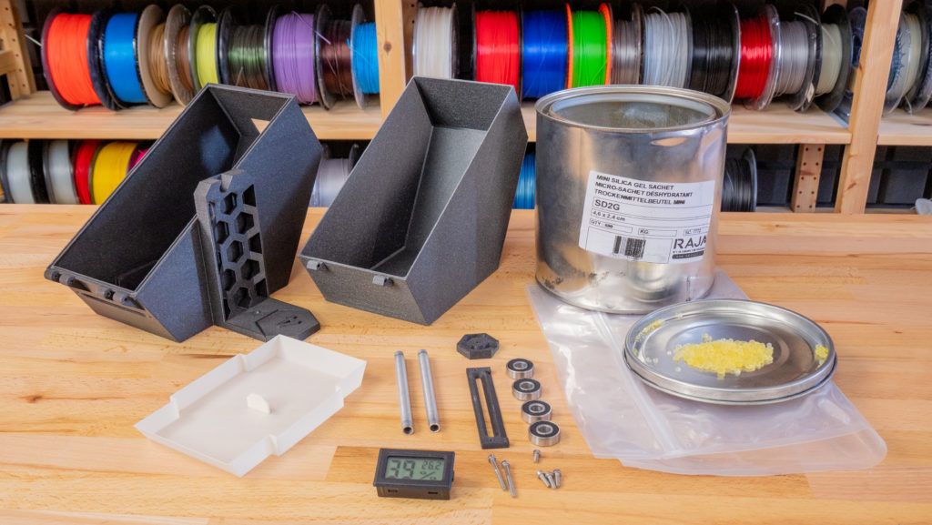
If something goes wrong when pressing in, or if you want to remove the ball bearing from the pulley again, the Tool_Bearing_Press_Out and Tool_Bearing_Press_Counter can be used. How this works is written down in the chapter Pressing a ball bearing out of a pulley in the appendix.
Assembling the filament roll storage
Then one of the 485 mm M8 threaded rods is inserted into one of the rod mount and secured with two M8 nuts on both sides. Simply use two 13 mm open-ended wrenches for this. Do not overtighten to avoid damaging the 3D printed bracket. The short, free end of the threaded rod should protrude approx. 13 mm beyond the nut.
Then put on a pulley and tighten it with a third nut so that the nut and the threaded rod end are flush.
Now do the same on the second hole of the rod mount with the second threaded rod. Then it should look like the photo.
Now pull on the rollers and spacers on the long free side. Repeat this in following pattern: roll – spacer – roll, and then repeat. So thread a total of 10 rollers and 5 spacers.
The spacers prevent that later, when two filament rolls run close to each other, a stationary roll is driven from a moving one, or a stationary roll is blocking a moving one.
Check that all adjacent pulleys are separated by a spacer and that the pulleys are not hitting anywhere else.
There is a little clearance between the ball bearing and the threaded rod. This results from the fact that the outer diameter of the threaded rod is approx. 7.8 mm in diameter and the inner diameter of the ball bearing is approx. 8.0 mm. This means that the roll can be tilted a little, especially if the filament roll is at the outer end of the pulley surface. It must be checked whether the pulley lying next to each other are separated far enough by the spacer so that they do not touch each other when the two are inclined inwards. If this is the case, print a second spacer and place it in between. If the inclination of the rolls is too extreme that a stable unwinding of the filament roll cannot be guaranteed, measure the diameter of the ball bearing and the threaded rod and replace them if necessary.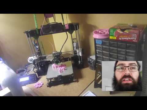
Repeat on the second threaded rod.
Once all the pulleys that should later run between the brackets have been drawn up, the end on the second side is prepared. In addition to the rod mount, you also need 2 pulleys and 6 M8 nuts.
First of all, 2 nuts are screwed on, the free ends of the threaded rod should protrude approx. 30 mm.
Thread the rod mount onto the two threaded rods.
Secure the rod mount with 2 nuts. As before, do not overtighten to avoid damaging the 3D printed rod mount.
Put on 2 pulleys and secure them with nuts.
Congratulations, the filament roll storage is ready. Time for a beer!
Step 2: Building the filament outlets into the airtight box
Required purchased parts
- 1 pc air-tight box* (approx. 17 EUR / pc)
Of course, other air-tight boxes can also be used, as already mentioned, please check the dimensions first and adjust the length of the threaded rod and the number of pulleys.
I have 4 of the linked boxes (IRIS 50L) in operation and I am very satisfied, they are super air-tight and offer enough space for up to 6 rolls.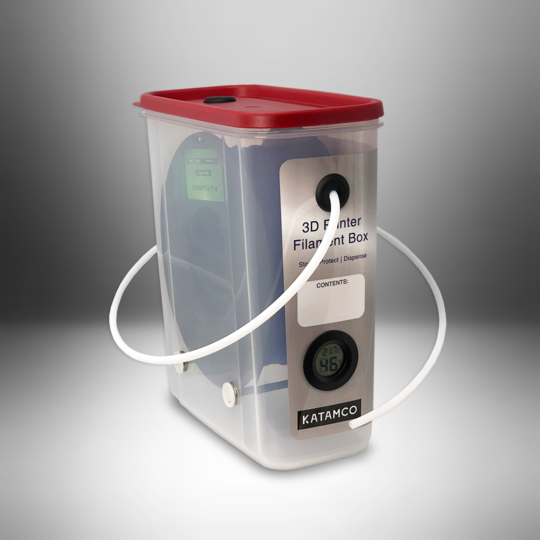
- PTFE tube OD4 ID3* (approx. 6 EUR / m)
Alternatively, a PTFE tube with an outer diameter of 4 mm (OD4) and an inner diameter of 2 mm (ID2) or an OD5 ID3 tube can also be used.
This picture shows the three possible PTFE tube variants with an 1.75 mm filament. It fits well with the ID2, and of course at ID3 there is more space and therefore less friction. This is an advantage if you want to build variant B with long filament guides.
If you build your filament box for 2.85 mm filament you have to choose a PTFE tube with an inner diameter of 3 mm (ID3).
Required 3D printed parts
- 6 pcs 000700_Filament_Outlet_175_OD4
- 6 pcs 000800_Nut
Layer height 0.2 mm and 100% infill (rectangular)
If an OD5 PTFE tube is used, then use the 001400_Filament_Outlet_175_OD5 STL-file.
For 2.85 mm filament, use the STL files 001500_Filament_Outlet_285_OD4 or 001600_Filament_Outlet_285_OD5.
It is essential to print these parts (Filament_Outlets) with 100% infill and a mechanically resilient material (PETG, ABS, ASA, etc.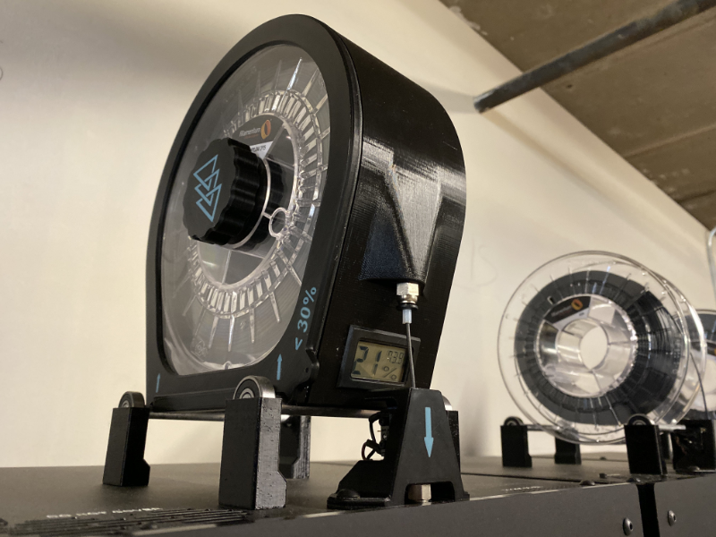 ). Tests of an external tester have shown that components printed with PLA can break when they are clamped or after a while after assembly.
As a test, pull filament (1.75 mm or 2.85 mm, depending on the design of your box) through the borehole of the printed Filament_Outlets and check for clogging and ease of movement. If necessary, remove print residues or burrs, correct or drill out until all parts for the selected filament diameter run smoothly.
For variant A – Simple plug
- 6 pcs 000900_Plug_OD4
- 6 pcs 001000_Clamping_Ring
Layer height 0.2 mm and 100% infill (rectangular)
If an OD5 PTFE tube is used, then print the STL-file 001700_Plug_OD5.
For variant B – Plug is fixed at the filament box
- 6 pcs 001100_Clamping_Plug_OD4
Layer height 0.2 mm and 100% infill (rectangular)
If an OD5 PTFE tube is used then print the STL-file 001800_Clamping_Plug_OD5.
Drill the holes in the air-tight box
To do this, mark the drilling pattern shown on the box using a marker or a foil pen.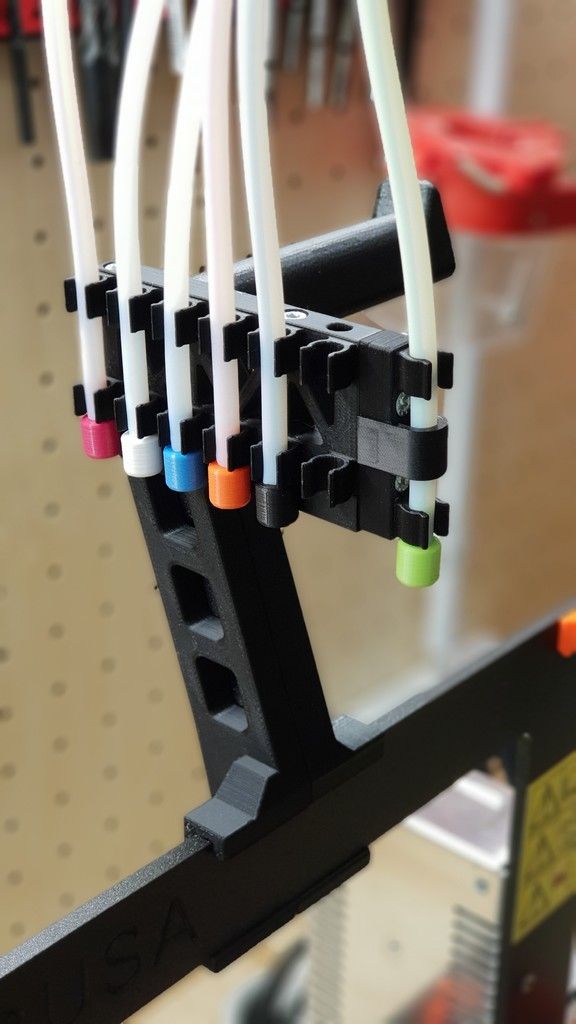 To do this, mark 6 holes in the middle at a horizontal distance of 75 mm and 45 mm above the floor. The holes must have a diameter of 16 mm, then the filament outlets fit neatly and seal well. To make life a little easier, Flo created a drilling template to mark the correct distances, here to download on thingiverse.
Prepare the cordless screwdriver, 2 mm and 4 mm wood drill bits and the step drill.
On the step drill, all steps larger than 16 mm can be taped off as a precaution – so nothing goes wrong when opening the holes.
Sharp wood drill bits are very suitable for the plastic of the box, it is important to exert only little pressure on the box – too much pressure could break it, so it’s best to pre-drill with the small 2 mm drill and then prepare the hole for the step drill with the 4 mm drill. Use a slow drill speed at step drill and slowly widen the hole.
Wear protective goggles to protect against chips.
This is what the box should look like with the 16 mm holes.
Insert the selected filament outlet from the inside through the hole and screw it with the 3D printed nut from the outside.
Tighten the nut only by hand – hold the inside against it – check whether the filament outlet is pulled completely into the hole.
Repeat this for the other 5 filament outlets.
Now it’s time to attach the PTFE tubes, here you can choose between two variants. Regardless whether variant, A or B it’s still very easy to switch between the two variants later, you are able to print the required components with only a few grams of filament.
Variant A – Simple plug (Variant B is dealt with immediately afterwards)
Cut the selected PTFE tubes into short pieces of 10 to 20 cm using a box cutter. Make the cut neatly straight. Push the pieces of tubing into the filament outlets until they are stopped on the inside edge, some force is require
Use cut-resistant underlay, wear work gloves.
If the tube is fully inserted in the outlet, it is fixed with a clamping ring.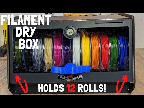 The cone of the clamping ring is pushed over the cone of the toothed gripper of the outlet and thus clamps the tube. When pressing on, always hold the outlet on the inside of the box against the pressure. The embossed arrow on the clamping ring must point towards the filament box.
The PTFE tube is sealed by the 3D printed plug, due to a cone on the inside which also clamps the plug on the tube.
Repeat for the remaining filament outlets.
Variant B: Plug is fixed at the filament box
Use a box cutter to cut the selected PTFE tubes into long pieces, depending on needed length to the printer, in this example it’s 70 cm. Make the cut neatly straight.
Use cut-resistant underlay, wear work gloves.
Push the tubes into the filament outlet until they are stopped at the inside edge, some force is required here.
If the tube is fully inserted in the filament outlet, it is fixed with the clamping plug. The cone of the Clamping_Plug is pushed over the cone of the toothed gripper of the outlet and thus clamps the tube.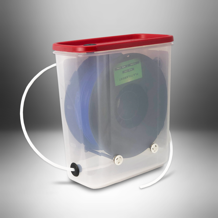 When pressing on, always fix the filament outlet on the inside and hold against it. The embossed arrow on the Clamping_Plug must point in the direction of the box.
The long PTFE tube is then sealed by simply pressing it from above into the 3D printed clamping plug, sealing it with a cone on the inside and at the same time fixing it.
Now repeat the procedure for all remaining filament outlets.
With this variant, always make sure before printing that the PTFE tube cannot be pulled or squeezed into the extruder or the mechanics on the 3D printer.
Very good, the most difficult part is done and the filament box is almost ready!
Step 3: Tape the filament roll storage into the filamet box
In order to prevent the filament roll storage from slipping in the filament box, it is recommended to fix the filament roll storage in the box with double-sided adhesive tape.
All you need is scissors and double-sided tape.
Cut the tape so that it fit under the filament roll storage. Remove the protective film and stick the holder in the rear half of the filament dry box.
When positioning, it is best to insert the largest roll of filament to be stored and to check whether it hits the back wall of the filament dry box.
Leave enough distance to the walls of the dry box and after gluing in, test whether the largest roll of filament to be stored can also rotate freely. Otherwise change position and test again.
Done, now all that’s missing is the filament box lid with the integrated silica gel holder to finish your dry filament storage box.
Step 4: Attach silica gel holder to the lid
The last step is to prepare the lid. A bag with silica gel is housed here so that it does not disturb the filament rolls when they are turning. There is also the possibility to use loose silica gel, check the free 3D print files of the silica gel box and the instruction for the silica gel box. In my opinion, the handling of the bags is a little less problematic, the handling of loose silica gel usually ends with the crackling sound of the granules on the floor.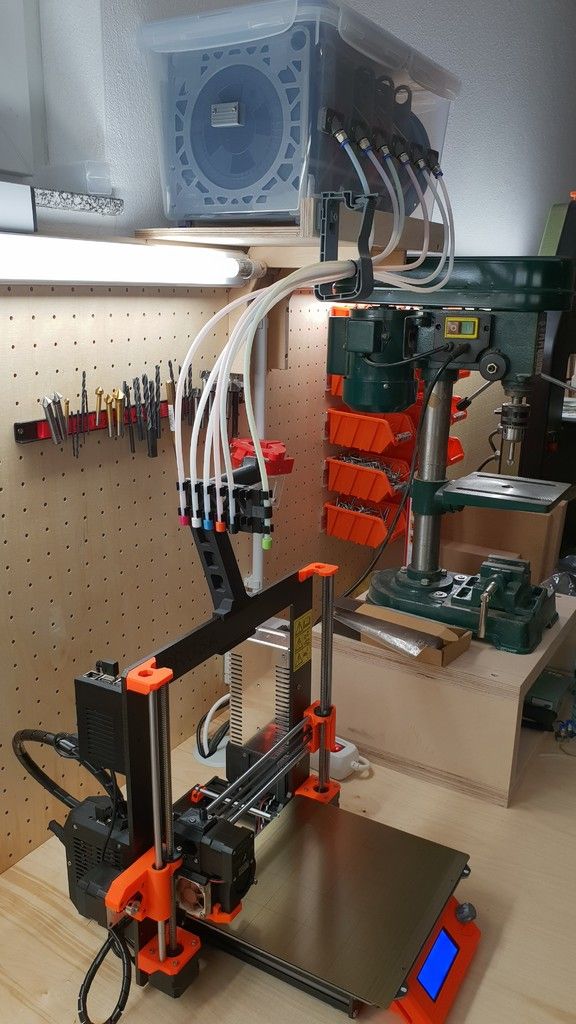
Required purchased parts
- 1 pc Silica Gel Bag* (approx. 7 EUR)
- 4 pcs Cylinderhead screw M3x14 DIN912* (approx. 7 EUR / 50 pcs)
- 4 pcs Nuts M3 DIN934* (approx. 7 EUR / 50 pcs)
Required 3D printed parts
- 2 pcs 001200_SilicaGel_Carrier
- 1 pc 001300_SilicaGel_Plate
Layer height 0.2 mm and 20% infill (rectangular)
Assembling the silica gel holder for the filament box
Put the two carriers together with the plate and screw the 4 cylinderhead screws into the pre-printed holes.
Test the plug-in connection between the two carriers and the plate, if this is too loose best glue the parts together or print the plate again, scaled a little larger.
The 500 g silica gel bags have plenty of space on this silica gel holder.
To fix the holder in the filament dry box lid, 4 holes with a diameter of 4 mm must be drilled. For the holes, first mark the distances between the two central ribs on the cover.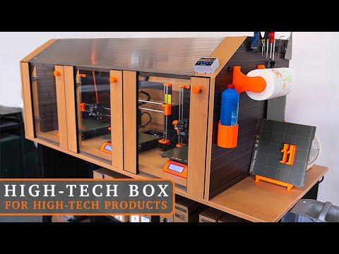
The first two holes should be placed approx. 15 mm away from the rubber seal. The next two holes then follow at a distance of 160 mm. It is best to place a mark again about 5 mm from the edge of the rib.
Again it is best to pre-drill the holes with the 2 mm wood drill bit and then set the final holes with the 4 mm wood drill. Due to the lack of space, the cordless screwdriver has to be set at an angle. Drill slowly so that the cover is not damaged when the ribs are pierced.
Attention when drilling at an angle, there is a risk of slipping! Wear protective goggles to protect against chips!
Place the silica gel holder between the two central ribs, inserting the screws through the holes.
Now fix the holder with the 4 pcs M3 nuts.
Finally slide the silica gel bag under the holder. Now the lid is ready.
Put the lid on the box and check whether the holder and the silica gel bag are seated properly.
Check the stability of the screwed bracket and the secure fit of the silica gel bag.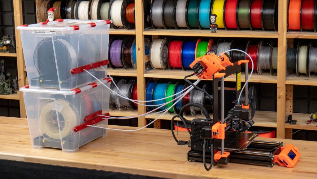 It must not come off when the filament dry box is in operation.
Step 5: Load the finished filament box and test it out
Thread the filament of the filament rolls to be stored into the filament outlets and adjust the pulleys to the width of the filament roll. Gradually insert all the rolls and then close with the lid.
When inserting the filament rolls, check that they can rotate freely and that they do not touch the floor or the walls of the storage box – if a filament roll scrapes or blocks, this roll is not suitable for the filament storage box.
If the filament blocks or can only be pushed through the outlet under a lot of pressure, the outlet and the PTFE tube must be checked for blockages or too small bore diameters and cleaned or replaced.
Inserting and threading the filament is described in more detail in the operation manual immediately afterwards.
Awesome! It’s done, your filament dry box is ready for use. In my experience, the silica gel only needs to be regenerated every 3 to 6 months.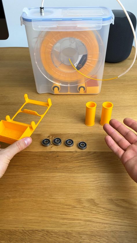 Enjoy printing!
The filament dry box also works perfectly in combination with the DIY 3D printer enclosure, the filament which should be printed can be easily plugged in and out. The 3D print files of the DIY 3D printer enclosure can be found in the web shop.
Operation manual filament box
Inserting the filament rolls:
Move the pulleys on the threaded rods so that the filament roll to be inserted is securely and centrally on the 4 pulleys after it has been inserted.
Align the filament roll so that the end of the filament is at the bottom of the filament roll and points towards the filament outlet, see the attached sketch with the correct direction of rotation of the filament rolls. Always pull the filament end off the filament roll from below, as parallel as possible to the bottom of the box and thread it straight into the outlet.
Push the filament through the PTFE tube until the filament end protrudes out of the tube at the front.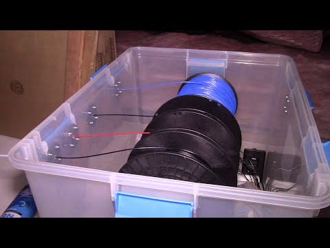
At the end of the PTFE tube, leave 1-2 cm of filament protruding, in order to then put on the plug or insert the tube into the clamp plug until it sits well and firmly.
When inserting the filament rolls, check that they can rotate freely and that they do not touch the floor or the walls of the storage box – if a filament roll scrapes or blocks, this roll is not suitable for the filament storage box.
Check whether the filament is threaded into the outlet parallel to the floor and as straight as possible, and that nothing is preventing the filament from being pulled out. Also check the correct direction of rotation of the filament spool and correct it if necessary.
Check whether filament has become tangled on the filament roll – if necessary untangle and rewind.
If the filament blocks or can only be pushed through the outlet under a lot of pressure, the outlet and the PTFE tube must be checked for blockages or too small bore diameters and cleaned or replaced.
Check the ease of movement of the pulleys, the condition of ball bearings and rollers at regular intervals (every month).
Always perform a safety check on the filament box before 3D printing
Perform the following safety check before 3D printing!
- Check whether the filament roll is stable on all 4 pulleys.
- Check whether filament has become tangled on the filament roll – if necessary untangle and rewind.
- Check whether the selected filament roll can rotate freely and is not in contact with other filament rolls.
- Check that the filament roll holder is parallel to the wall of the filament storage box and that the filament rolls do not touch the walls of the storage box.
- Check the filament feedthroughs and PTFE tubes for blockages and whether the filament can be easily pulled through and check that the filament runs smoothly.
- If a long PTFE tube is used up to the 3D printer, then make sure before printing that it cannot be pulled or squeezed into the extruder or the mechanics of the 3D printer.
- Check whether the silica gel bag or the silica gel holder is blocking or touching the filament or the filament roll.
Maintenance of the desiccant (silica gel):
Check the color of the silica gel (desiccant) at regular intervals (1-2 weeks) – if the saturation of the silica gel is reached very quickly (less than 4 weeks), the box may be leaking.
When saturation is reached (discoloration of the indicator dye) regenerate the silica gel bag according to its instructions.
Normally the selected silica gel bags (for 100ml water absorption) last about 3 to 6 months until it is saturated and has then to be regenerated according to its instructions.
Do not leave silica gel granules or bags open in the room for too long – always store them in the closed filament storage box or a closed plastic bag! Also keep the opening of the box to change a filament roll as short as possible, so the desiccant lasts longer without having to be regenerated.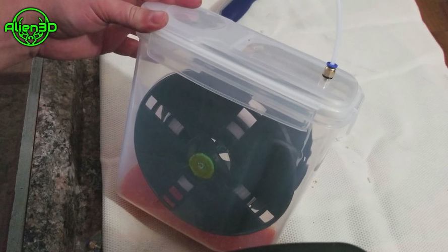
Disclaimer:
The instructions and the associated files are an inspiration of Ingenieurbüro Dr. Janko GmbH to build this project yourself. Since Ingenieurbüro Dr. Janko GmbH has no way of checking and influencing the required quality of the printed components and purchased parts as well as the quality of the assembly and the correct functioning of the project or if any inadmissible changes and modifications to the project has been made, Ingenieurbüro Dr. Janko GmbH accepts no liability for functionality, stability or the damage incurred by the project.
Appendix – Additional tipps and tricks
Pressing a 608 ball bearing out of a pulley
If something went wrong while pressing in or if the ball bearings should find a place in another project, the process of pressing out a bearing is shown here. With the aid of the inculded 3D printed tools it is quite easy.
In order to remove a pressed-in ball bearing from a pulley, the 3D printed parts Tool_Bearing_Press_Out and Tool_Bearing_Press_Counter are required.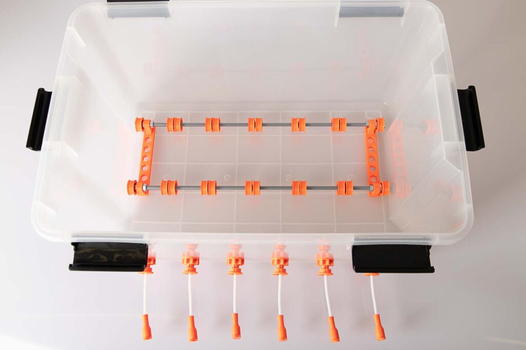
Place the pulley on the counter so that the open side faces down towards the desk. This allows pressing out the ball bearing and to fall into the counter part.
Place the press-out tool in the middle of the ball bearing and press firmly,
until the ball bearing is fully pushed out.
The ball bearing is already removed from the pulley and can be removed from the counter part.
Free 3D file Dry box (low vitamin)・3D printer design to download・Cults
Foldable tablet stand
1.18 €
Folding phone stand
1.18 €
3M Command Headphone Duck Stand with Bracket
Free
nine0003 Simple soap dishFree
Shaving brush Razor and soap holder
Free
Parametric Filament Concentrator
Free
Eclipse Goggles
Free
Ender 3 Bracket for Plate 9 Flame Arrestor0004
Free
The best files for 3D printers in the Tools category
Bosch Professional 18V Battery Wall Holder ProCore and Old type Minimalistic Bracket Organize Accu
1. 25 €
25 €
Covid 19 Amesis Project Mask Mask
Free
ALPHABET BRAILLE + Ñ
Free
Peugeot radio removal key
Free
Multi-Color Angular House
Free
Garden finger claw
0.61 €
Triangle electric cabinet lock core shaft replacement
Free
nine0003 Screwdriver rack for desktop or pegboardFree
Bestsellers in the Tools category
Ender 3, 3 V2, 3 pro, 3 max, dual 40mm axial fan hot end duct / fang. CR-10, Micro Swiss direct drive and bowden compatible. No support required for printing
1. 57 €
57 €
PET-Machine, make your own plastic bottle filament at home! nine0004
15 €
Rapid print paint bottle rack (6 sizes)
2.84 €
Display holder FLSUN v400
9.99 €
ENDER 3 S1/S1 PRO COIL HOLDER AND DEPORTED COIL
€2.13 -20% 1.70€
SUPERBOX
1,50 €
Ender 3 S1 BEST cable guide - vertical
2,50 €
Fire hydrant container
1.89 €
PRECISE DIAL INDICATOR 3D PRINT DIY
1.91 €
nine0003 well designed: Hemera fan duct 2. 50 €
50 €
Ratchet holders - magnetic - holders for tool box organization
2,68 €
ARTEMIS -> Shop for Alligator 2 || 6.5" arrows || Repeating crossbow
6.25 €
Paint stand with scissors
5.21 €
PRECISION CALIPER 3D PRINT DIY
3,13 €
telephone ring holder
0,90 €
Printer boxes for Ikea Lack Table
1,99 €
Do you want to support Cults?
Do you like Cults and want to help us continue our journey on our own ? Please note that we are a small team of 3 people, so it is very easy to support us in maintaining activities and creating future developments.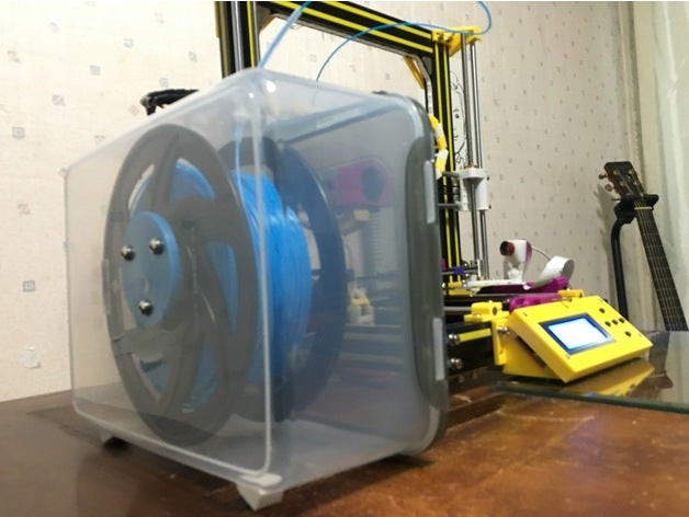 Here are 4 solutions available to everyone:
-
ADVERTISING: Disable the AdBlock banner blocker and click on our banner ads.
-
AFFILIATION: Shop online with our affiliate links here Amazon.
-
DONATIONS: If you want, you can donate via PayPal here.
-
* INVITE FRIENDS: * Invite your friends, discover the platform and great 3D files shared by the community!
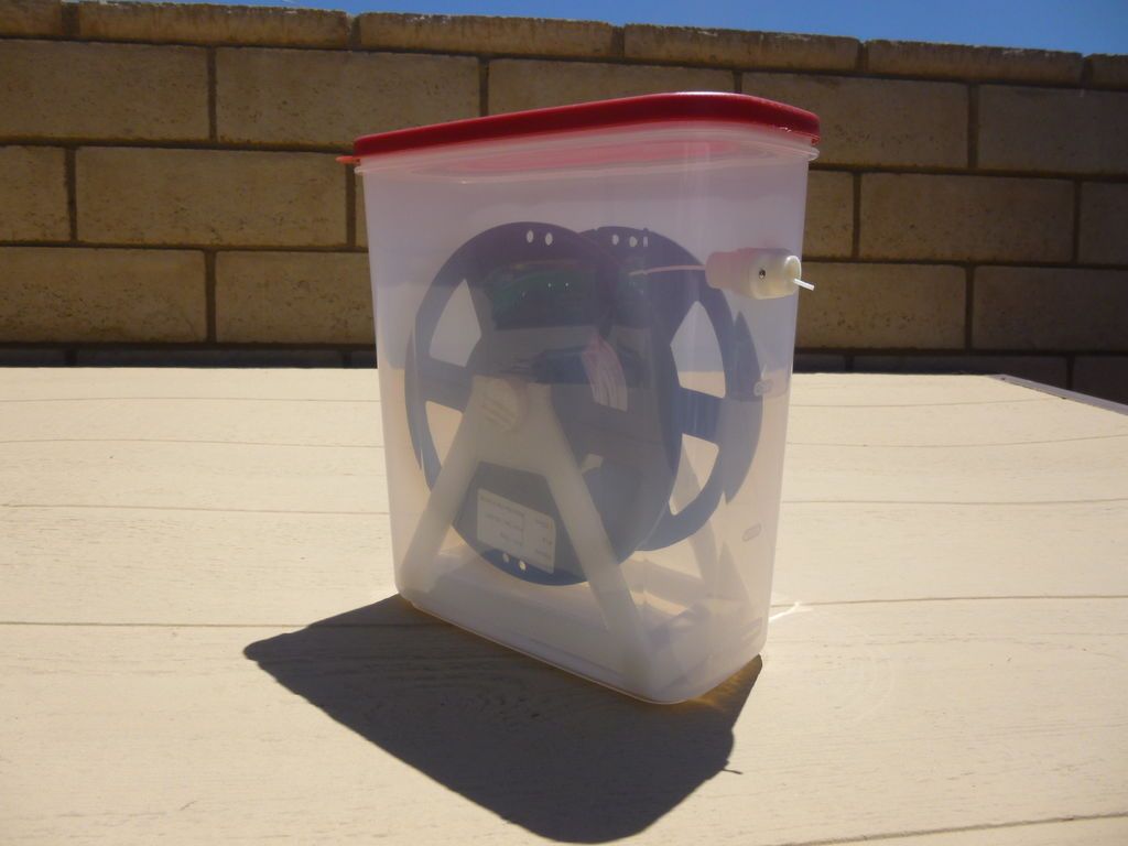
Free STL file Nebula Series Print Drybox・Model for download and 3D printing・Cults
Nebula Drybox is the first of a series of 3D printing accessories that I plan to develop for use in my own workshop and for sharing with the 3D printing community. The goal of the project is to create useful structures that are efficient, durable and have a pleasing modern aesthetic. nine0006
This box helps limit moisture absorption during printing and is designed to accommodate most common spool sizes up to 210mm in diameter and 80mm wide.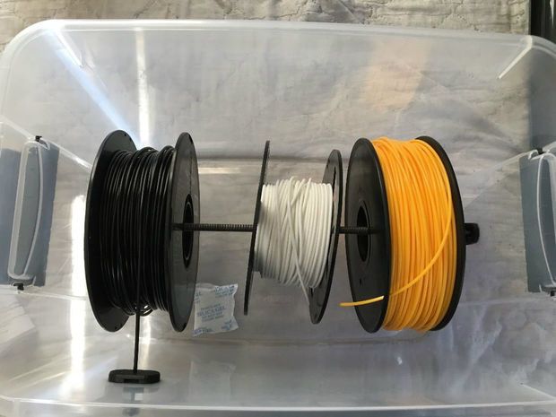 Multiple roller attachment points also allow the use of smaller spools.
The west coast of Canada experiences high humidity for most of the year. Keeping the filament dry requires frequent maintenance; highly hygroscopic materials can absorb a significant amount of moisture from the air during the day of printing. Tools like foil bags, airtight storage chests, and dry print boxes are a must. If you're looking for a simple desktop drybox that doesn't require a lot of materials and has a nice look, try the Nebula Drybox! nine0006
What you will need:
Printer capable of printing 240 mm prints.
Low warp filament such as PLA, PLA+, or PETG (approx. 440 g in all parts).
4x 608 bearings
Pneumatic coupling 9.5 mm
Short (or long) length of PTFE tube
Knife/scalpel for deburring holes. (recommended)
Dehumidifier to keep the interior dry.
Nylon zippers
Anti-slip pads (optional)
How to print and assemble:
Ground clearance test:
(Recommended) Print out a small 'Outlet Size Test.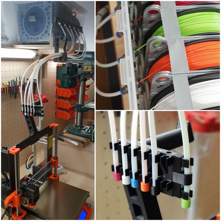 stl' file (bottom flat side down, no supports) to check the fit between your seal and the air clutch. If it's too tight to fit, you may need to change the settings or clean/widen the hole with a hobby knife (a friendly reminder of knife safety). If instead it seems loose, you can always use glue or epoxy. nine0006
Base:
Print the file 'Drybox Base.stl'. Depending on your settings, this should only take 140-160 g of material. To obtain a smoother contact surface between the lid and the base, it is recommended to turn on ironing (for best ironing results, first calibrate the settings on small test cubes). To improve media efficiency, you can turn off the initial bottom layers and print with a skeletonized underside. However, for PETG, I still recommend using at least one initial undercoat for better plate adhesion. nine0006
Lid:
The dry box lid has been designed to be lightweight and optionally printed with a single wall thickness of 1mm to the rim. Thus, it is similar to a vase, but with separate layers and a z-seam. If you can't print it with one wall, you can use 0.5mm line width to print two.
Using the latest version of Cura, here are the settings I've had success using the 0.4mm nozzle.
◘ Wall Line Width = 1.2mm (setting a value greater than 1mm causes Cura to use one wall on corner lots)
◘ Top/Bottom Line Width = 0.5 (for cleaner infill)
◘ Walls = 1 ( important, otherwise you might end up with some too thick walls with gaps in the lower layers)
◘ Layer Height = 0.2 mm (You can increase this setting a little, but remember that at this stage you are already printing a lot of material for nozzle 0, 4 mm)
◘ Temperature = Slightly higher than your normal profile. nine0006
◘ Speed = Not too fast or you might get fluctuations.
Printing such thick walls on a 0.4mm nozzle often works well, but only on a single wall. When in doubt, stick to a line width of 0.5mm.
The wall diverges in the last section to create a thick rim. This helps to create a rigid contact surface with minimal material consumption.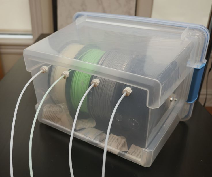 If you want an even smoother surface, you can turn on ironing on the last layer. nine0006
PLA is your friend here as it has low thermal expansion and warping. There are two versions of the cover: flat and corrugated. I don't recommend trying to print a flat version out of anything other than PLA, as the walls can sink in or bulge out. The corrugated version has better strength/stiffness and is also recommended when printing PETG or other cap materials.
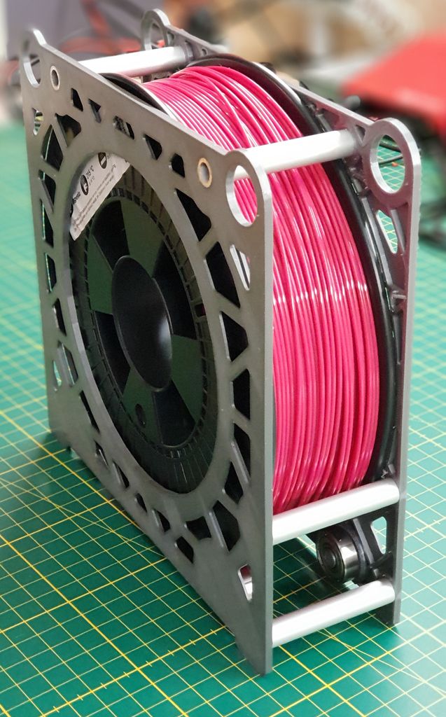
High rollers:
Print two rollers from the 'Drybox Roller 608.stl' file (print standing up with the supports touching the plate). Use material with good interlayer adhesion and hot printing; matte or silk PLA may not be the best choice in this case depending on their z-strength (varies by brand and settings). PETG is a great material, but clean removal of the support can be a problem. PLA+ might be the perfect choice. nine0006
Alternatively, use a piece of 8mm aluminum pipe or rod that fits into the bearing bore and cut to length.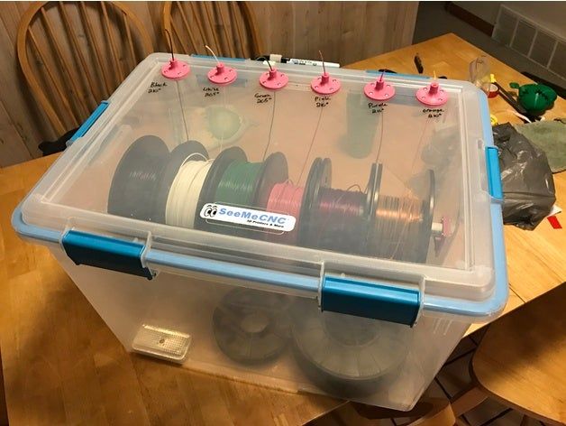 Or even print a thin 8mm rod from something with good layer adhesion. Or use a wooden pin. There are many options.
(Optional/Experimental!) Has adapter and roller with suffix 625, can be used with 625 bearings assembled from worn POM wheels instead of 608 bearings. I found the 4.8mm spindle on them to be brittle when printing on PLA. A possible solution to increase the strength of a thin spindle could be to print the rollers in half. nine0006
Tray:
(Optional) Print the "Drybox Desiccant Tray.stl" desiccant bag holder (recommended line width is 0.5 mm). You can also skip the tray and simply add the desiccant packs to the empty reservoir at the bottom of the base. If you are adding a desiccant to the tray, please make sure you are using the large ball type and not the salt-like pieces (otherwise it will leak all over the place).
PETG is an excellent tray material. It can be thrown whole into a dehydrator to renew packages without fear of deformation. nine0006
Assembly:
Attach the bearings to the ends of the rollers and snap them into the slots in the base (optional, glue them to the spindle so they don't fall off the rollers when removed from the dry box, recommended when using 625 bearings and adapters).