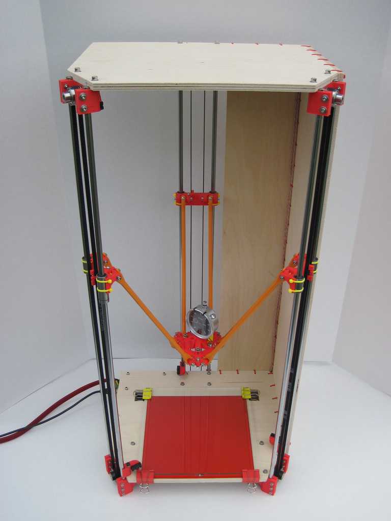
Diy cnc router 3d printer
Simplest CNC Machine with Minimum Parts Possible
In this tutorial I will show you how I built the simplest CNC machine with minimum parts possible and without using a 3D printer. That’s right. I’ve been using 3D printers for most of my recent projects because, of course, they are great for prototyping as we can easily make any shape we want with them. However, not everyone has a 3D printer, so therefore I wanted to show you that we can also make stuff even without the help of 3D printers or other CNC machines.
You can watch the following video or read the written tutorial below.
Overview
I will show you how I built this CNC machine by using just a single power tool, a drill, and several hand tools. The material that I used for this build used is 8mm MDF board, which is actually quite strong and probably more rigid than a 3D printed PLA material and at the same time it’s easy to work with.
For this video I will use this CNC machine as a laser engraver, and in a future video I plan to make it work as a pen plotter.
Obviously, this type of construction of the machine cannot provide much rigidity so we cannot use it as a CNC router or a mill. Though, if we attach a more powerful laser, we could use it to cut various materials, like this MDF board that we are using here or other type of wood boards and with quite good accuracy.
The working area of is quite big 390 by 360mm, and the level of details that this laser engraver can produce is pretty impressive. To be honest I was surprised how good the engravings turned out.
The brain of this CNC machine is and Arduino UNO board in combination with a CNC shield, but more details about that as well as how to prepare your drawings or images for laser engraving, make G-codes and control the machine using free, open-source programs, a bit later in the video.
DIY CNC Laser Engraver Machine 3D Model
I started by designing the machine using SOLIDWORKS for Makers. The two main components of this CNC machine are these MGN15H linear rails together with their suitable sliding blocks.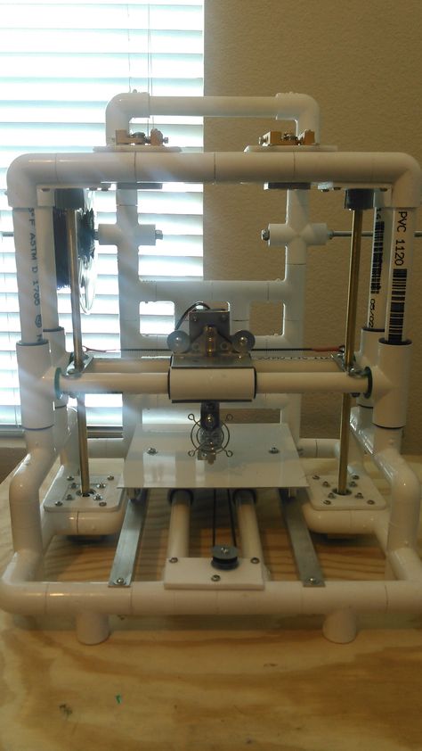
For driving the blocks or the two axes, we are using two NEMA 17 stepper motors and some suitable GT2 pulleys and timing belts. For connecting everything together we are using 8mm MDF board, and for homing the machine, two micro limit switches.
And that’s it, a CNC machine with minimum parts possible.
You can download the 3D model here:
You can find and download this 3D model, as well as explore it in your browser on Thangs:
Download the assembly 3D model from Thangs.
Thanks Thangs for supporting this tutorial.
Here’s the drawing of the central mounting plate:
See also: Arduino CNC Foam Cutting Machine
Assembling the machine
All right, so now we can start building the machine. Here’s a list of components needed for assembling this DIY CNC machine. The list for the electronics components can be found below in the circuit diagram section of the article.
- MGN15H Linear Rail ………………………… Amazon / Banggood / AliExpress
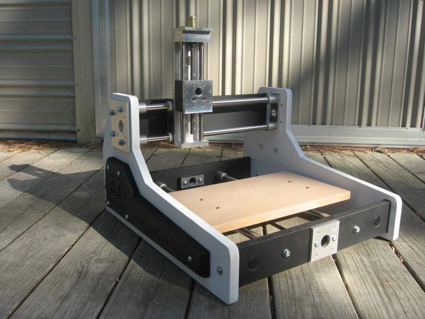
- Stepper Motor – NEMA 17 ………….
 … Amazon / Banggood / AliExpress
 - GT2 Belt + Tooth Pulley…………………… Amazon / Banggood / AliExpress
- GT2 Idler Pulley ………………………………… Amazon / Banggood / AliExpress
- Spacer Nuts …………………………….…….. Amazon / Banggood / AliExpress
- Bolts and Nuts set …………………………… Amazon / Banggood / AliExpress or from local hardware store + Flat Head Screws 3x16mm
- M2x20 x2, M3x12 x20, M3x16 x6, M5x25 x5, 3x16mm screws x20
Disclosure: These are affiliate links. As an Amazon Associate I earn from qualifying purchases.
Here’s the 8mm MDF board that I will use, and according to the drawings that I took from the 3D model, now I will cut the pieces to size.
Related: DIY Pen Plotter with Automatic Tool Changer | CNC Drawing Machine
For that purpose, I used the simplest possible method, a pencil for marking where I needed to cut and a hand saw to cutting them.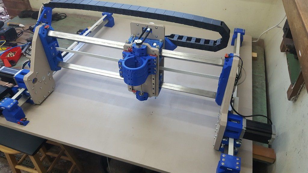
Of course, it requires some effort to cut all the pieces by hand, but still, we can get them pretty nice and clean even with this method.
Once I cut all pieces to size, I moved on with making the holes on them. Making the holes precisely is actually more important than cutting the pieces. The holes positions must be very precise as they have to fit with the other parts which have precise and fixed dimensions, like the linear rails and the stepper motors.
The central plate where the Y-axis and the stepper motors are mounted has many holes and in order to get them right, I printed a drawing of that part in real size.
Normal printers are easily accessible to everyone, so I though it won’t be a cheating if I used one for building this project. In this way we can position the part and the drawing and mark the locations of the holes. Then we can drill the holes, although this doesn’t mean that we will get them 100% accurate. We are still doing the job by hand, so we have to be very concentrated and patience to get them right.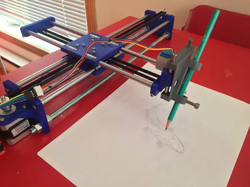
We need 3 and 5mm drill, as well as one 25mm drill for making the opening for the stepper motor.
Next, I continued with assembling the base of the machine, on which the X-axis rail will be secured. For that purpose, I marked the position where the rail support part should be fixed, and drilled two holes on the base part, and one hole on the support part.
Then I secured these two parts with the first 3mm screw and some wood glue. With the first screw in place, I checked for squareness and then pre-drilled the second hole on the support material with 2mm drill.
In similar way, I added two brackets for better support.
To be honest, this method of assembling these MDF parts is not that good, as it’s really hard to get them square as everything we do is by hand and the MDF boards are just 8mm tick which additionally complicates this process. Maybe a better and easier way would be to use metal brackets which you can easily find them in a hardware store.
Nevertheless, once I had the two sides ready, I installed the X-axis rail to them.
These MGN15H rails provide very smooth and play free movement, as their sliding blocks have balls or rollers inside them.
Before installing them, we should clean and grease them well. I secured the linear rail in place with two M3 bolts on each side.
Next, we need to install the Y-axis on top of the X-axis sliding block. For that purpose, we will use the central plate.
Again, we are using M3 bolts for securing the parts together. For securing the stepper motors in place we also need M3 bolts.
In addition to that, for one of the steppers I’m using some distance nuts in order to get a proper mounting height for it, though I probably could have mounted this stepper at the bottom side of the plate and so we would have to use those distance nuts.
For driving the X-axis, we need to install two GT2 idler pulleys near the stepper shaft so that we can create a proper tension between the belt and the stepper pulley.
We need M5 bolts and nuts for securing them.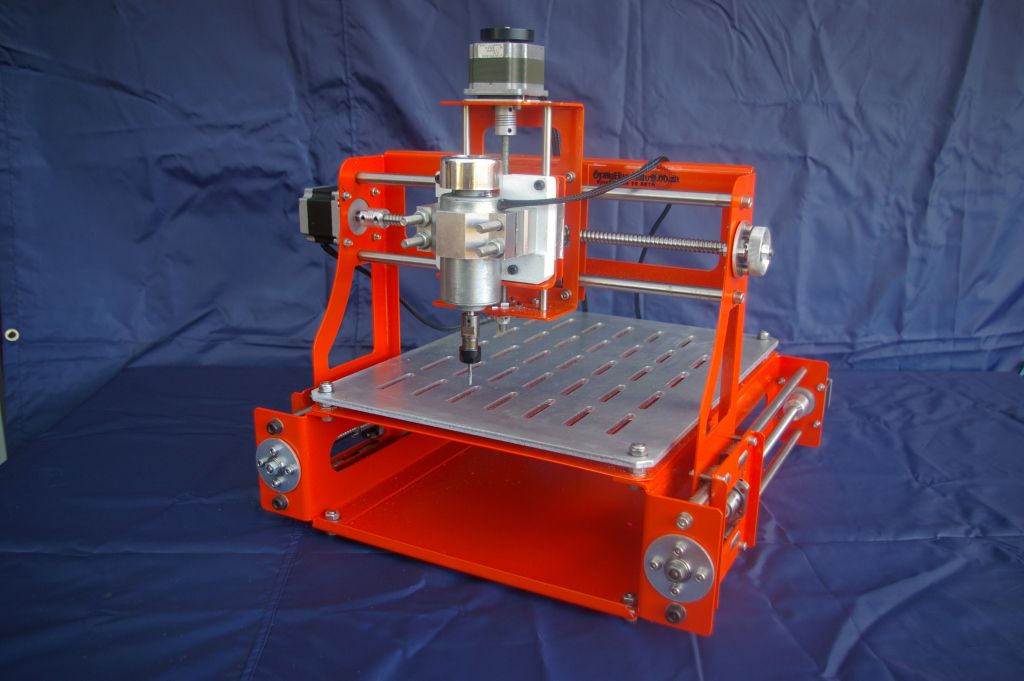 As for the Y-axis, we need only one idler pulley on the other side of the rail, as the belt for this axis will be installed in a loop.
All right, so next is the marriage or connecting the X and the Y axes rails together. We do that using four M3 bolts. This connection is crucial to be precise as the precision of the whole machine depends on it.
Using a square ruler, we must check whether the two axes are perpendicular to each other, and if not, we should adjust them properly.
Next, we can install the parts which go on the Y-axis sliding block and actually hold the end effector or the laser module in this case. Using the method explained earlier, I assembled these parts and secured them to the sliding block using four M3 bolts.
Now we can secure the laser module in place with two M3 bolts.
I continued with installing the GT2 belts. I measured how much length I need and cut the belt to size.
For securing the belt to the sliding block I used two M5 bolts and zip ties.
I secured the first side of the belt to the M5 bolt with a zip tie, and then tensioned the belt on the other side and secured it to the second bolt with the zip tie.
As for the X-axis, the belt will be stretched in line from one to the other side while passing through the three pulleys in a way that will provide tension or grip with the stepper motor pulley.
I secured the belt on both sides with a single bolt and square MDF piece.
With this our CNC machine is almost done. There are few more things that we need to do.
At the bottom side, I glued some furniture pads so that the machine stays more firmly in place.
Then I installed the micro limit switch for the Y-axis. We need two M2 bolts for that purpose.
As for the X-axis limit switch, I forgot to make those holes on the central plate, so I marked them and drilled them on site.
It was a bit tight securing this limit switch in place but at the end it came out well.
Connecting the electronics components
The mechanical part is now completed, so we can move on with connecting the electronics components. As I mentioned, we will use an Arduino UNO board in combination with a CNC Shield and two DRV8825 or A4988 stepper drivers.
I will secure the Arduino board on the side of the machine, so I mark two Arduino holes and drilled them with 3mm drill. I used a 5mm distance nuts between the side panel and the Arduino board.
Read more: Stepper Motors and Arduino – The Ultimate Guide
The CNC shield simply goes on top of the Arduino board. We need to insert 3 jumpers for each driver so that we have the highest stepper resolution selected.
Please note here that these three jumpers should be removed as we don’t need them. I used them in one of my previous projects.
Then we can connect the stepper motors in place with the provided cables. For connecting the limit switches, we need two wires connection.
I soldered the one end of the wires directly to the endstops, and on the other side I soldered female pin headers so I can easily connect the to the CNC shield.
As for connecting the laser module, we need 3 wires, GND, 12V and a signal line for a PWM control. These wires need to be a bit longer so they can reach the farthest point of the machine.
On one side we have the 3-pin connector that goes in the laser module, and on the other side we have the GND and 12V wires that will go to the power supply connector of the CNC shield and the signal line that needs to be connected to the Z+ or Z- endstop pin.
DIY CNC Laser Engraver Circuit Diagram
Here’s the circuit diagram of how everything needs to be connected.
You can get the components needed for this project from the links below:
- Stepper Motor – NEMA 17……………… Amazon / Banggood / AliExpress
- DRV8825 Stepper Driver……….……..… Amazon / Banggood / AliExpress
- Arduino CNC Shield ………………………. Amazon / Banggood / AliExpress
- Arduino Uno………………………………..… Amazon / Banggood / AliExpress
- Limit Switch …………………………………. Amazon / Banggood / AliExpress
- DC Power Supply ………………………….
 Amazon / Banggood / AliExpress
 - Laser Module ………………………………. Amazon / Banggood / AliExpress
- Laser Safety Goggles …………………….. Amazon / Banggod / AliExpress
Disclosure: These are affiliate links. As an Amazon Associate I earn from qualifying purchases.
So, we are using an Arduino UNO board in combination with a CNC Shield and two DRV8825 or A4988 stepper drivers. We have two micro limit switches for homing the machine and a 12V Laser module which can be PWM controlled. For powering we need 12v power supply with a minimum current rate of 3 amps.
Firmware and Control Software
With this, we are actually done with assembling the machine. What’s left to do now is to give life to it or make it a real CNC machine. For that purpose, we need to install a firmware to the Arduino for controlling the motion of the CNC machine.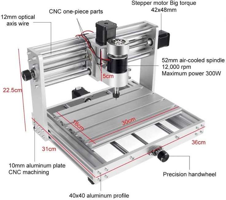
The most popular choice for DIY CNC machines is the open source GRBL firmware. In addition to the GRBL firmware, we also need a control software through which we will send G-codes and tell the machine what to do. In this case we will use the LaserGRBL controller. This software is specifically made for controlling laser engravers with the GRBL firmware, and I can tell you that it’s really an amazing controller for that purpose considering it’s also open source.
With LaserGRBL we have an option to directly flash or upload the GRBL firmware to the Arduino so we don’t have to do that manually. We can even choose a ready to use version for two axis machines with just X and Y homing, just like the one we need.
So, once we flash our Arduino with the GRBL firmware, we can connect our machine with the controller and open the GRBL configuration window so we can adjust some parameters according to our machine.
The first thing that we should adjust here is the travel resolution or the steps/mm values for the X and Y axes.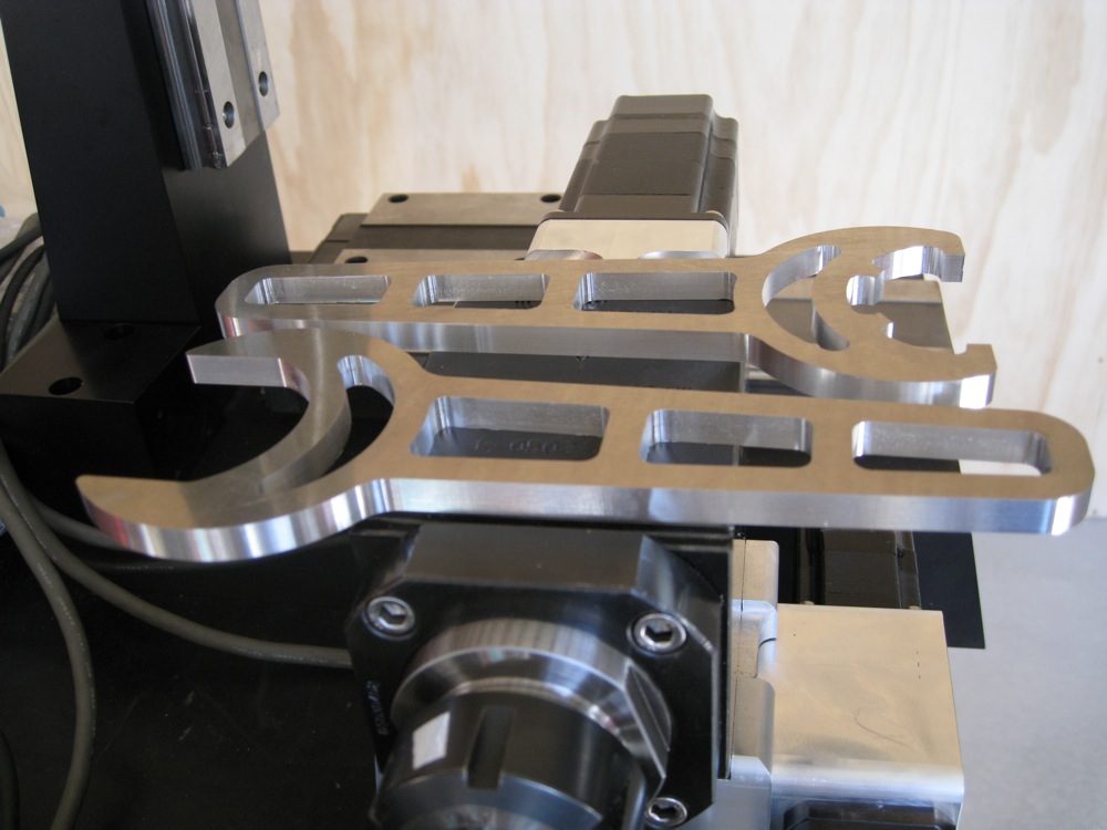 These values indicate how many steps the motor should take in order to move 1mm. This depends on the type of stepper motor that we have, the selected step resolution and motion transmission, in this case the GT2 belt and pulley.
Here’s how we can calculate these values for our machine. The default values here are usually 250 steps/mm. Now we can move the machine using the JOG commands, for example 20mm, and we should notice how much the machine will actually move.
In my case, for 20mm jog on the Y-axis, the actual movement was 31mm.
So, 20/31 = 0.645, and if we multiply that value with 250, we will get 161.29. So, that’s the value that we should set as a steps/mm value for our machine.
If we try to move the machine now with the updated values, the machine should move the exact distance. If you are not happy with the result you can still fine tune these values by drawing squares and measuring them. I ended up using a value of 160 steps/mm.
Nevertheless, there are other important parameters that need to be adjusted as well. For example, we should enable Hard limits which are the actual limit switches, Soft limits which defines the working area, set the Homing direction which defines where our limits switches are located on the machine and so on.
You can download my set of parameters so you can just import them into your firmware.
Generating G-codes for Laser Engraving
Another great thing about this software is that it also has a built-in G-code generator. This means that we can load any photo, clip art, pencil drawing and so on, directly into the software and we can generate a G-code for engraving according to our needs. The rastering image tool is quite versatile with many options to choose like, selecting Line to Line tracing, Vectorizing, 1bit BW Dithering etc.
Of course, if you want you can also generate G-code with other software, like for example Inkscape and its plugin Inkscape-Lasertools for generating G-codes and load them here. I already explained how to use this method for generating G-codes in my previous video, for the SCARA Robot laser engraver, so for more details you can check that video out.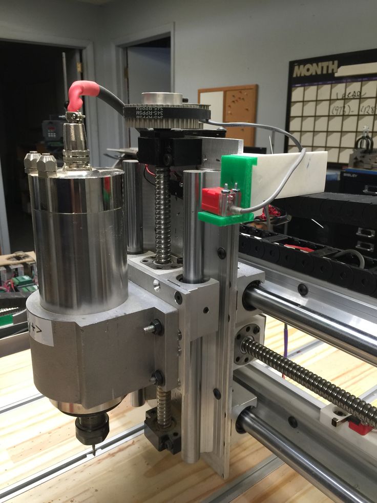
Now I will show you how you can generate a G-code for laser engraving from a photo using LaserGRBL. Here I have a photo of a dog, which I will open with the software.
Using the Brightness and Contrast option we can adjust the image to our desire. We can choose the type of conversion of the photo, for example, Line to Line tracing, 1 bit BW dithering or a vector format. I will use Line to Line tracing for this photo and here we can also select the line direction and the quality of the engraving which is defined by how many lines per mm there will be.
Next, we can select the Engraving Speed, set the minimum and maximum PWM values for the laser power, and set the size of the engraving.
And that’s it, the software will generate the G-code for this engraving. Before we start the it, we can use the Frame button to outline or show us where the engraving will take place, so we can adjust our work piece as needed.
Please note that we must use laser safety goggles that will protect our eyes from the ultraviolet light of the laser, as it’s very dangerous.
If we have calibrated our machine correctly, we can get quite good engravings. For calibrating we could use this image that I made which has squares from 100% to 10% transparency.
According the results adjust the engraving speed and PWM value for the laser power.
Here you can download the calibration image:
So, that’s it for this tutorial. I hope you enjoyed it and learned something new. If you have any questions feel free to ask the in the comments section below and don’t forget to check some of my other Arduino Projects.
5 Best 3-in-1 3D Printer (with Laser Engraving & CNC) 2023 Update
- Last Updated: January 31, 2023
- Pat Nathaniel
Bored of your current marriage with your 3D printer? Want more spice in your life? Maybe you’re looking to cheat on your 3D printer with a CNC milling machine?
Well what if I tell you that you could have the best of both worlds.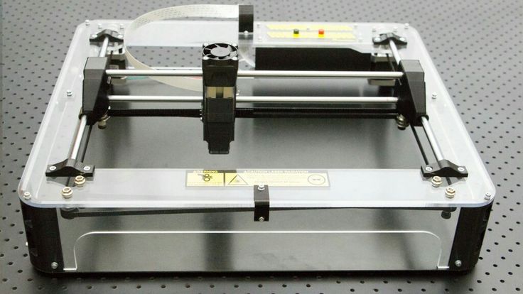 Thanks to all-in-one 3D printers, it has never been easier to stay faithful!
More than just 3D printing, these machines can laser engrave, CNC machine, print food (you heard that right, your future machine-wife cooks as well), and much more!
Snapmaker 2.0
Build Volume: 320 x 350 x 330mm
Get Discount (Official Store)
Check Latest Price
Snapmaker Original
Build Volume: 125 x 125 x 125 mm
Get Discount (Official Store)
Check Latest Price
Zmorph Fab
Build Volume: 250 x 235 x 165mm
Get Discount (Official Store)
Check Latest Price
Table of Contents
- What’s an All-in-One 3D Printer?
- All-in-One 3D Printing Functionalities
- 3D Printing
- Laser Engraving/Cutting
- CNC Milling
- Paste Extrusion/Syringe Extrusion
- Hot-Wire Cutting
- Drawing
- Vinyl Cutting
- How Good are these 3D Printers?
- Top All-in-One 3D Printers At A Glance
- 1.
 Snapmaker 2.0 (Best Value)
 - 2. Snapmaker Original (Best Budget)
- 3. Zmorph Fab (Premium Choice)
- 4. Creality CP-01
- 5. E3D ASMBL Tool Changer
- 1.
An all-in-one 3D printer is a jack-of-all-trades kinda machine. As I mentioned, it can 3D print, laser engrave, CNC machine, print food, and more.
All kinds of people use these 3D printers – hobbyists, engineers, businesses, chefs, etc. They can be a godsend to those who don’t want multiple machines taking space in their house. Additionally, buying all those contraptions can significantly rack up your expenditure.
All-in-One 3D Printing FunctionalitiesLet’s look at the different capabilities of these machines.
3D Printing
If it wasn’t already obvious, 3D printing is the main function of an all-in-one 3D printer. For those not familiar with 3D printing, it’s a process by which material is deposited layer by layer to create a 3D object.
Laser Engraving/Cutting
Laser cutting uses a high-powered laser to cut into materials like metal, plastic, and wood to create objects in different shapes. Laser engraving, on the other hand, uses a low-powered laser to engrave on similar materials.
CNC Milling
CNC milling is a popular method used in subtractive manufacturing (the process of removing materials to create different objects). A rotary cutter moves along a pre-programmed path to cut the block to be milled.
Paste Extrusion/Syringe Extrusion
With paste extrusion, a syringe is used to print objects made of filaments such as PVC foil, wax, EVA foam, etc. Even food can be used as filament, as long as it’s made into a uniform semi-solid paste.
Hot-Wire Cutting
In hot-wire cutting, a heated wire of stainless steel is used to cut polystyrene foams and other materials.
Drawing
Perfect for artists, this tool uses a pen to draw computer-programmed illustrations on any surface.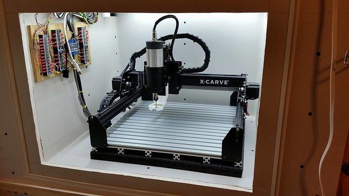
Vinyl Cutting
This process uses a drag knife to cut designs or letters into thin adhesive plastic surfaces.
How Good are these 3D Printers?An all-in-one 3D printer is a Jack-of-all-trades. But you know Jack; the guy doesn’t seem to master anything.
Don’t expect these compact machines to perform each task like a champ. Ideally, these 3D printers would serve hobbyists the best. On the other hand, if you’re running a full-scale business, you may want to reconsider.
Top All-in-One 3D Printers At A Glance1. Snapmaker 2.0 (Best Value)
2. Snapmaker Original (Best Budget)
3. Zmorph Fab (Premium Choice)
4. Creality CP-01
5. E3D ASMBL Tool Changer
One of the most funded Kickstarter 3D printing projects ($7.85M to be exact), the Snapmaker 2. 0 follows boldly in the footsteps of its predecessor. It surpasses the Snapmaker Original; not by a huge margin, but just enough to keep you hooked.
Available in three sizes:
- The A150 (160 x 160 x 145mm) – considered the direct replacement to the itty bitty 125 x 125 x125mm build volume of the Snapmaker Original
- The A250 (230 x 250 x 235mm), and the
- A350 (320 x 350 x 330mm)
The build size is the only difference in all these models.
The 2.0 improves upon the original in a few ways. The automatic bed leveling, a feature lacking in the older version, is one of the welcome additions in the new one. Another cool upgrade is the camera module on the laser tool head. A final noteworthy upgrade is the option of varying CNC milling speeds.
The Snapmaker 2.0 inherits the good looks from the original, it looks gorgeous and oozes with class. The body is made of machined metal – you can see the care taken in crafting the machine. If you love machines, you may lust for this one.
Looking at the 3D printing side of things first, the A350’s build volume of 320 x 350 x 330mm makes it the Godzilla of 3D printers.
Print quality is pretty good; the prints came out nice and smooth. Just don’t expect world-class printing (remember, it’s Jack).
Printing is unfortunately slow, a snail may race past this one. The 3D printer trudges along to get the job done.
The laser engraver does its job well. You can engrave on materials like plastic, leather, wood, non-transparent acrylic and more.
There are four lasering modes: Black & White, Greyscale, Vector, and Text. Another feature is the camera, with which you can take a picture of the uncut material block. The picture then shows up on your design software, with the help of which you can easily align the design in the software.
CNC milling improves upon the original, while some things stay intact. The primary changes are hardware related, and they get the job done more efficiently.
If you’re looking for the best value for your money (especially the A350 with it’s ginormous build volume) , you can’t go wrong with the Snapmaker 2.0.
- The 3D printer is a stunner
- Print volume is large, especially in the A350 version
- Good 3D printing and laser engraving
- Slow 3D printing speed
Get Discount (Official Store)
Check Latest Price
2. Snapmaker Original (Best Budget)The legend of the Snapmaker series began with this machine. It was also one of the most funded Kickstarter projects, raising around 2. 2 million from its backers. When it was first released it was the best modular 3D printer under $1000.
Packaging was awesome; if you’ve had any experience with Apple packing, you’ll know what to expect.
After unboxing the machine, you need to set it up. And that takes time. Luckily, the kind folks at Snapmaker provide you with step-by-step instructions so that you won’t get stuck anywhere.
Build quality is once again apparent in the 3D printer. Each module (3D printing, CNC, and laser) feels solid.
Changing between different modules is a fluid and easy process. Unscrew a couple of screws, remove a cable, fix the new module, and rescrew. All in a minute’s work.
Print quality was good in our test print. We found no noticeable errors, and I was happy with the final results. You can also use a wide range of materials as the nozzle can attain temperatures of 250°C.
The laser tool module has a laser of power 200mW with a wavelength of 405nm. These specs are decent, and get the job done. I missed the presence of the 2.0’s camera though, as laser engraving was a ton easier.
If we look at the CNC milling side of things, the Snapmaker Original pales compared to the 2.0 – this CNC is rudimentary in many ways. Don’t expect industrial-level output on the machine, the CNC module is only meant for light-duty work.
Another disappointment was the work volume, with measly dimensions of 125 x 125 x 125 mm (the smallest version of the Snapmaker 2.0 had dimensions of 160 x 160 x 145 mm for reference). You won’t be winning any Guinness Records for the World’s Biggest Printer with this 3 in 1 3D printer.
But on the bright side, the 3D printer is much more affordable than its successor and it’s worth the price.
- Affordable
- Build quality is excellent
- 3D printing and laser engraving is good
- Poor CNC milling
- Small work volume
Get Discount (Official Store)
Check Latest Price
3. Zmorph Fab (Premium Choice)
 The Zmorph is an engineering marvel. If I had to choose one 3D printer among this list that captured my heart, it would be this one.
Sexy – that’s the adjective that comes to mind looking at the machine. I hope you aren’t attracted to machines, you’ll fall for this one (I think my machine-o-philia is slipping through in this article).
This 3 in 1 3D printer is as sturdy as a stubborn rock. For 3D printing, this is fantastic news – you don’t need to do any leveling as the build plate won’t budge. The rigidity also helps in the CNC milling.
3D printing with standard settings leads to good prints, with just a few kinks here and there. However, you can make masterful prints by playing around with settings, so your prints are in good 3D printer hands.
Ready for the feature that will blow your minds? (None of the other 3D printers have this)
This machine has a dual-extruder tool head!
With this unique addition, you can mix and match filaments. Or use the same filament with different colors. The print bed is your playground.
Secondly, let’s look at the laser engraving feature. Engravings are picture-perfect with little to no artifacts. There’s not much to say here, other than – wow. The laser is carried over from the discontinued VX which is a 2.8 watt blue laser diode. It’s not the strongest laser but it’s sufficient enough to cut softer materials and be able to engrave woods, plastics, and leather without overburn.
And lastly, the CNC module steals the glory with the best CNC milling I’ve ever seen in an all-in-one machine.
The Zmorph Fab is an upgraded version of the former ZMorph VX. Here’s a list of enhancements from the original model.
- The single extruder is upgraded for faster 3D printing.
- Addition of sensors to detect filament runout.
- The cooling fan is redesigned to cool better. This further results in faster printing speed.
- An improved aluminum work table for the CNC that improves rigidity.
- Improved software
- A HEPA filter that prevents the emission of 99% of particles released during the 3D printing process.
Be ready to shell out some serious dough. You may have to pick a few pockets, but it’s worth being on the wrong side of the law to get this beauty of a laser 3D printer and CNC combo.
- Beautiful machine
- Dual Extruder tool head
- Heated bed goes up to 115°C - great for ABS, PETG, plus HIPS and PVA
- All 3 modules do a fantastic job
- Expensive
Get Discount (Official Store)
Check Latest Price
4. Creality CP-01
 Yes, Creality had to put its hat into the all-in-one 3D printing ring. The CP-01 is their desktop 3D printer, laser engraving, and CNC milling answer to the success of the original Snapmaker.
And does it succeed? For the price, I’d say it does!
The setup was swift and simple, thanks to the instructions included with the 3D printer. The printer had excellent build quality and was sturdy.
Creality follows in the footsteps of Snapmaker to a tee with the 3-in-1 model (3D printer, laser engraver/cutting, and CNC milling).
I first tested 3D printing (because that’s where my heart lies). There was one feature I didn’t like – the rather bulky tool head. It prevented me from seeing the first few layers while printing.
The initial print turned out quite stringy, though that was mostly due to the initial settings (a common theme for Creality owners). I then adjusted the slicer settings and had a go again. Thankfully this time around the prints turned out clean. Surfaces felt smooth to touch and were rich in detail.
I then checked the laser module. Once again, switching from the 3D printer to the laser only took a few minutes. This ease of use makes it worthwhile to buy 3D printers like these.
The laser software was just as easy to use as the 3D printing slicer. The laser engraving was good, and I loved how the final piece turned out.
To get the best results in laser engraving, you only need to play around with one setting, and that’s the speed (as the power remains the same).
Be warned though: wear the safety goggles that come with a printer when using the laser. I cannot stress this enough. The lasering process also releases a lot of smoke, so I advise you to move this 3D printer to a ventilated area.
And now, let’s talk about the most inferior part of the machine, the CNC mill module.
The results from this were lackluster, you need to REALLY slow down speed settings to get a decent result. The machined portions were uneven at higher feed rates. I did manage to get decent prints at slower speeds, but of course, this took ages.
A major contributor to the poor performance in CNC milling is that the drill isn’t rigid and wobbles slightly.
But if you can forgive the CNC bit, Creality CP-01 is a fantastic machine that does a commendable job in both 3D printing and laser engraving. And as Creality’s 3D printers tend to be, the 3D printer is relatively inexpensive.
- Good 3D printing and lasering
- Relatively affordable
- The CNC milling was subpar
Check Latest Price
5. E3D ASMBL Tool ChangerIn all the above 3 in 1 3D printers, you cannot go all out on customizing the 3D printer.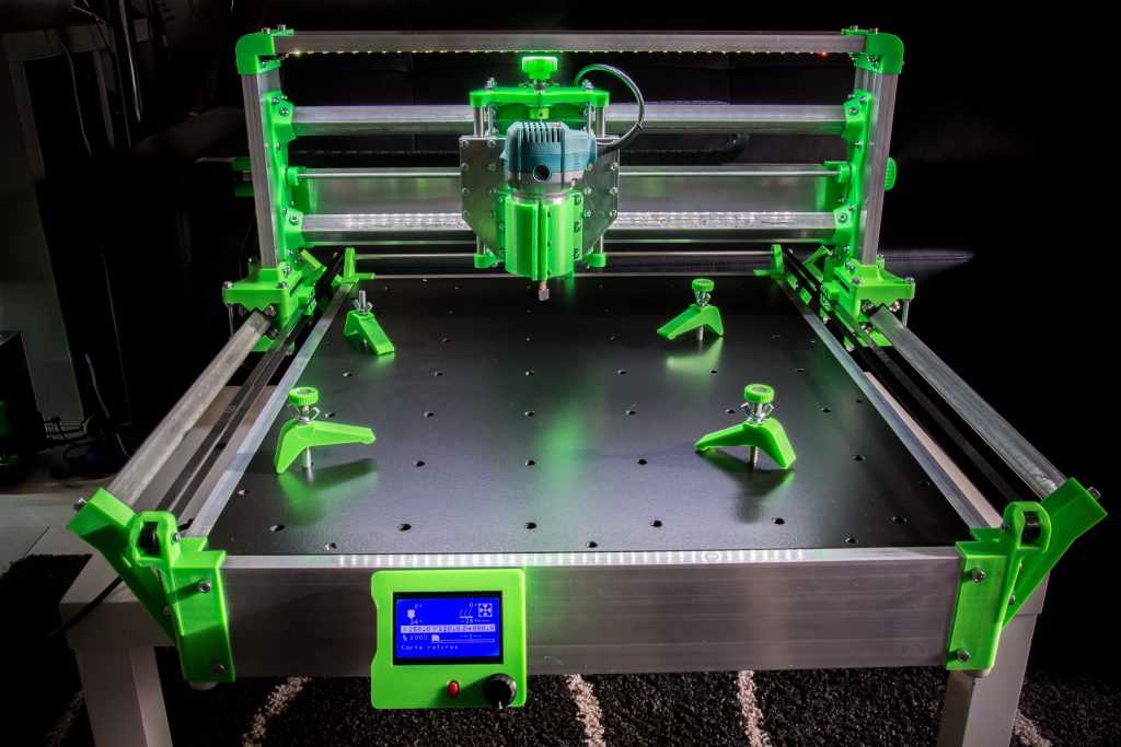 Understandably, the DIYers among you may want a machine that scratches your DIY itch.
Well, you can scratch away thanks to the E3D Motion system and Tool Changer.
The level of customization possible is staggering. In this printer, you can combine 4 multifunctional tools in a single print. Tools like laser engravers, CNC tools, extrusion tool heads, and more.
Just check out the hotend variety here.
E3Ds components are high-performance and best-in-class – built to meet the highest standards.
Spare parts like cable covers and spool holders among others can easily be downloaded on E3D’s GitHub.
The build volume is 300x200x300mm, which is extremely big.
You need to set up the 3D printer all by your lonesome, so if you’re really planning to buy this, be aware. You can get assembly guides to aid you here.
Using an automatic sensor leveling system, leveling is made easy.
And what about print quality?
I experimented with a few different tool heads, and boy was the print quality something to behold. The surfaces were smooth, and with the help of the milling tool, these surfaces could be made even smoother.
With a 3D printer of this complexity, you may require additional help from outside. If so you can always go to this forum: you’ll get all your questions answered by the company’s engineers.
Of course, the E3D ASMBL printer is an expensive one. Buying different parts and playing around with them makes it an even more costly affair.
But who says money can’t buy fun? You’re sure to get yourself entertained with the endless customizability offered by this 3D printer.
- Highly customizable 3D printer
- Great 3D prints
- A costly affair
Check Latest Price
Pat Nathaniel
Pat is the editor-in-chief at Printing Atoms.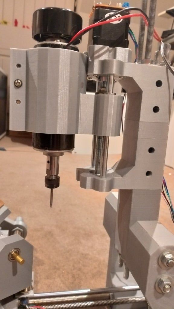 He has a BS in Mechanical Engineering from the University of Florida and wants to spread the word on 3D printing. When he's not writing, he likes to tinker with his Ender 3 Pro, test filament brands, and scuba dive.
CNC machine on 3D printer
Drawings of a CNC machine that can be printed on a 3D printer
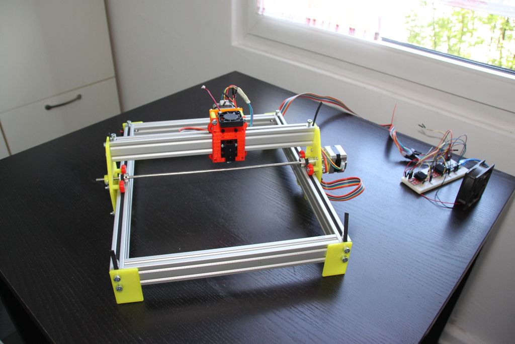
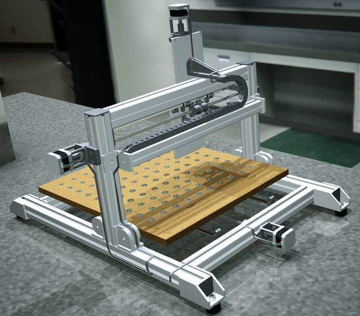
Probably every owner of a 3D printer has thought more than once that: 3D printing is, of course, good, but it would also be cheaper to make a CNC router. Wood costs an order of magnitude less than plastic, and if the object being manufactured can be assembled from flat parts, then plywood cut on a CNC machine turns out to be almost waste material. nine0008
At the end of this article, you can download drawings of CNC machine parts and print them on a 3D printer. Also in the article there is a video of the assembly and operation of this router.
The CNC machine turns out to be very technological and easy to assemble, in fact, after printing, you will have a constructor that you just need to connect with nuts and screws.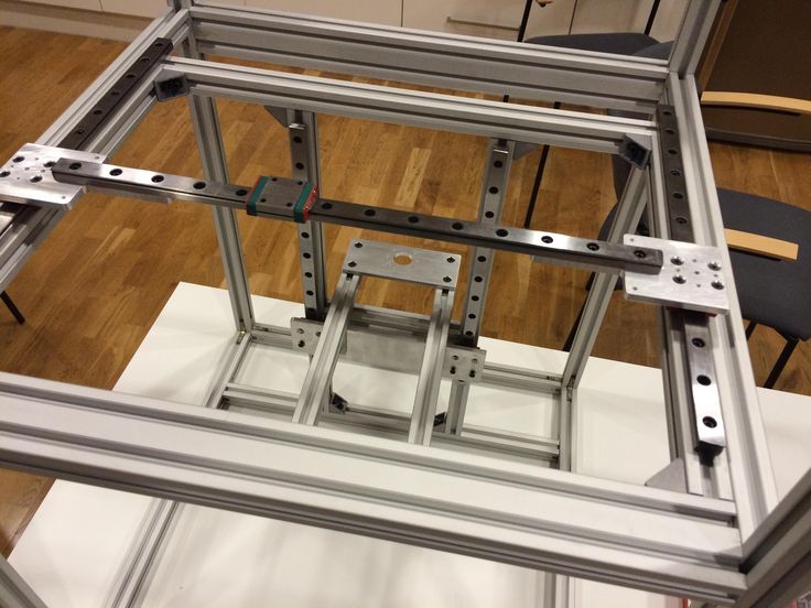
If you collected constructors in childhood, then you can also handle the assembly of the CNC machine! nine0008
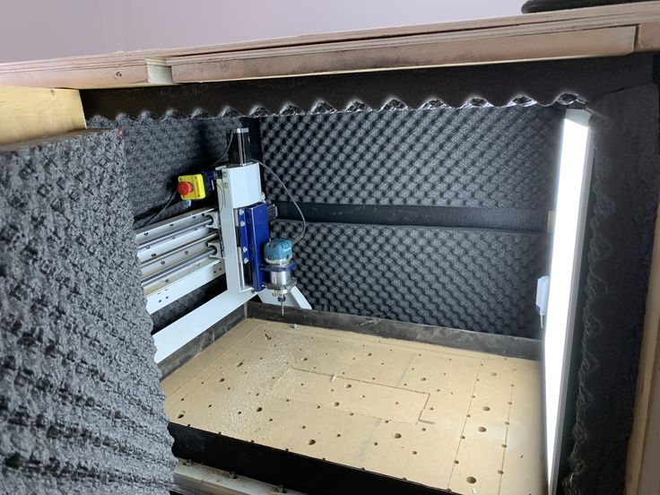
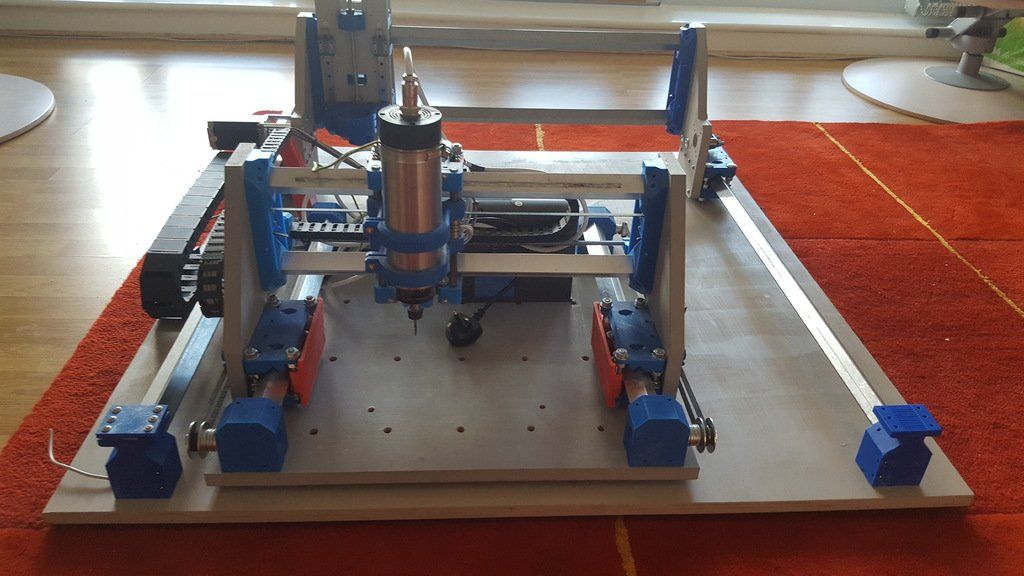
Despite the fact that the machine is assembled on parts printed from PLA, it is quite capable of working with the Makita RT0700C router - it is he who was photographed. You can also supply a budget spindle with Aliexpress ER1 500w, see links to electronics and spindle at the end of the article.
What you saw in the photos at the beginning of the article is a modified version of the CNC machine, with cable channels and connecting a vacuum cleaner. But initially the concept was much simpler and at the same time - it worked great! nine0008
Video of assembly and testing of the printed CNC machine
The video above shows the assembly of the CNC machine from parts printed on a 3D printer, as well as its test runs. Printing is done with PLA plastic, it is quite strong in bending and has less shrinkage than ABS plastic. See below for a list of fittings and electronics for assembly.
As you can see, despite the apparent fragility of the design, the CNC router performs test tasks without problems. And if you need faster work with a large depth of the cutter, then with this machine you can cut a set of drawings of a durable plywood CNC machine. nine0008
Like any other do-it-yourself homemade product, this CNC machine printed on a 3D printer has undergone improvements. Cable channels and a nozzle for connecting a vacuum cleaner are not only beautiful, but also practical! Detail drawings can be found in the archive with the machine itself at the link at the end of the article.
The third video shows another refinement, this time an increase in the size of the working area.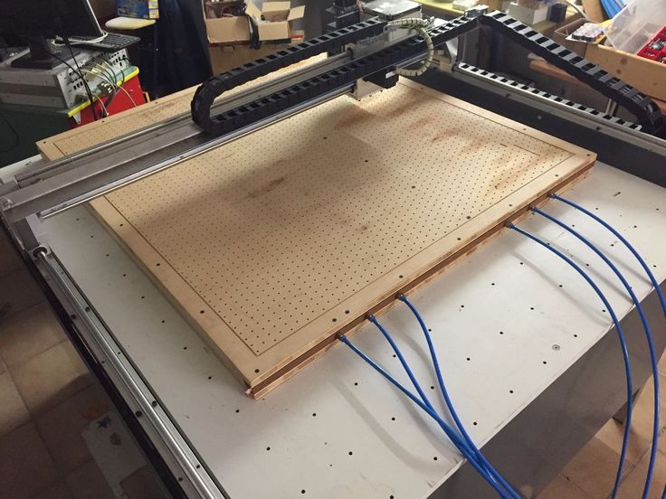 Fortunately, for such a refinement, it is enough just to change the profile to a longer one and put the corresponding lead screws, which in this case are made from an ordinary construction stud. nine0008
The whole alteration takes an hour, a maximum of two of your time. By the way, you can store the machine in disassembled form, assembly and disassembly takes only 10-15 minutes. If you only need the CNC machine from time to time, then you can save a lot of space in your home workshop by disassembling the CNC when you don't need it.
Accessories for assembling CNC machine
- 04x | Stepper motor Nema17
- 03x | Flange nut M5 / M8
- 04x | Aluminum profile 20x40 mm (see length according to your working area)
- 03x | Lead screw T8, with nut (100 mm shorter than aluminum profile)
- 14x | Nylon wheel with 5 mm bearing (type B in the link)
- 02x | Chrome steel rod 8 mm in diameter and 180 mm long (Z-axis)
- 01x | 200 mm lead screw T8, with nut (Z-axis)
- 04x | LM8UU linear bearing
- 03x | Standard 8mm bearing
- 01x | Pulley GT2 20 teeth, 5 mm inner diameter
- 01x | Pulley GT2 20 teeth, 8 mm bore
- 01x | Toothed belt GT2 200mm ~ 220mm
Screws and nuts (Also take a nut and washer for each screw):
- 12x | M6 x 30 mm screw nine0046 04x | Screw M6 x 35mm, 35mm VERY important for attaching the spindle to the Zaxis cart
- 26x | M5 x 50 mm screw
- 22x | M4 x 15 mm screw
- 08x | M4 x 10 mm screw
- 16x | M3 x 15 mm screw
- 20x | Wood screw 4mm (fixing the CNC machine to the base)
- 30x | M4 clamping nut
nine0007 CNC electronics
Arduino CNC Shield from Protoneer is used as control electronics, there will be a separate article about it soon.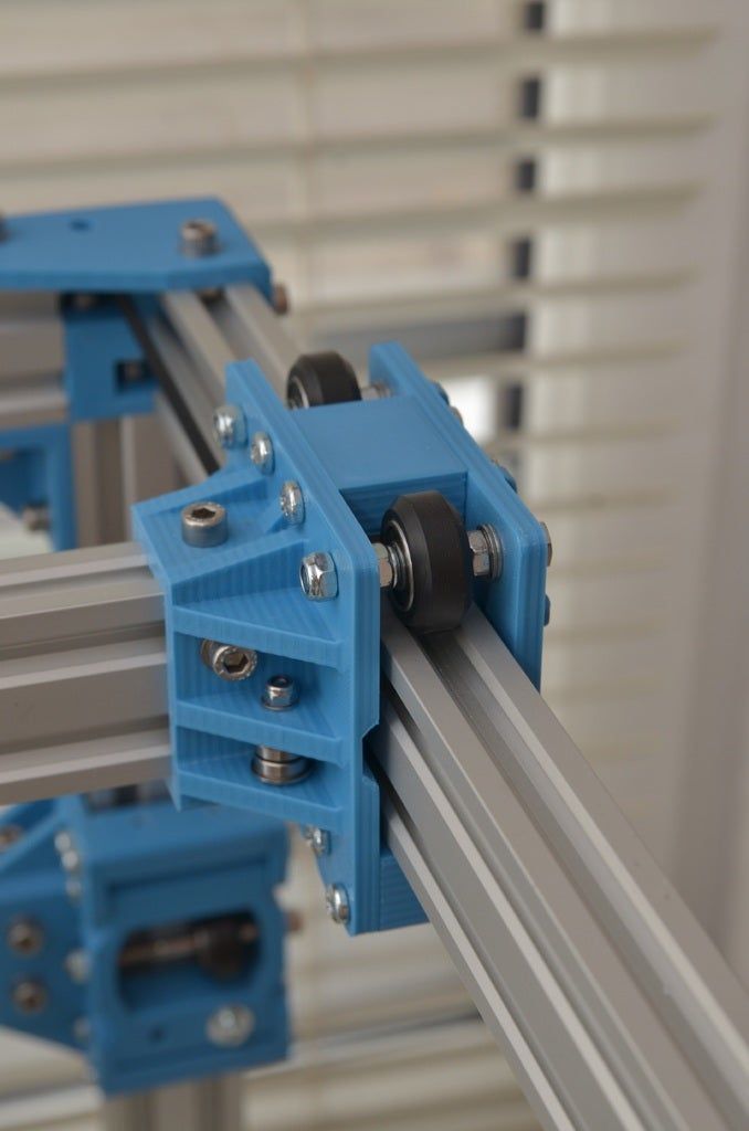
UPD . The article about electronics is ready and you can read it here: Electronics kit for CNC with USB connection.
The spindle can be used from small CNC machines 500W ER11, you can install Makita or DeWatt, or you can work on a budget one with a dremel. nine0008
Drawings of the CNC machine printed on a 3D printer
- Download drawings of CNC machine here
Konstantin, Overview of CNC machines
which is better for prototyping?
3D printing and CNC machining are more popular and affordable than ever. When you want to make a prototype, you decide what is best to use.
In this article, I will show you the strengths and weaknesses of each technology to help you make a decision. nine0008
Difference between 3D printing and CNC machining
The difference between 3D printing and CNC machining is that 3D printing is additive manufacturing while CNC is subtractive manufacturing. 3D printers have a nozzle that feeds layers of material to make parts, while CNC machining consists of a cutting tool that removes material to make parts.
CNC machines allow you to change the cutting tool according to the complexity of the application. As a result, CNC machines can be used to produce relatively more detailed products with high precision. nine0008
On the other hand, 3D printers are capable of creating complex shapes, making them ideal for rapid prototyping applications.
But is a 3D printer a CNC machine? Short answer: yes, it is a type of CNC machine that consists of a computer-controlled nozzle to print material.
However, 3D printing involves heating the working element, followed by cooling and solidification. This increases the total processing time required to manufacture the object. nine0008
In addition, there are many other differences that distinguish a 3D printer from a CNC machine.
Workflow
When you look at CNC machines and 3D printers from a technical point of view, both of these machines are controlled by a computer.
Interestingly, 3D printers belong to the CNC additive manufacturing industry.
3D printers are a kind of CNC machines.The CNC motion control system is responsible for moving the cutting head over the material. nine0008
In 3D printers, the cutting head has been replaced by a print head that applies material, and the controller controls its movement to print the desired shape or object.
Like any other CNC machine, 3D printers also have a similar workflow. Differences arise in the production process.
A typical workflow for CNC machines and 3D printers includes:
CNC machines use CAD/CAM software to create designs and G-code files that are programmed into the machine for production.
Most 3D printing applications only require a 3D part design file to print.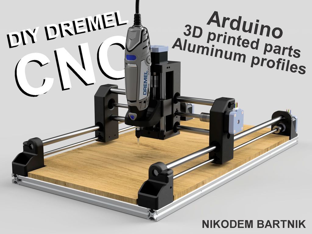 He then uses the CAM software to create a part program from the project. nine0008
The software used with 3D printers is similar to the CAM software used on CNC machines. They generate a G-code file used by CNC controllers.
Material Waste
CNC Metal MillingMaterial wastage in 3D printing is lower than in CNC machining. The main reason is that 3D printers only use the required material to create a part.
Because CNC machines use subtractive manufacturing techniques, they continuously cut out a block of material to give it the desired shape, resulting in a lot of material wastage. nine0008
Size and assembly
Compared to 3D printers, CNC machines are readily available in larger sizes. Making 3D printers more portable than CNC machines.
Most XXL rated CNCs have a footprint of a few square meters, while large 3D printers can have a maximum footprint of 1 square meter.
For example, some of the giant 3D printing machines have a build volume close to 1500×1200mm. While most industrial grade CNCs can have a working area of 3500 X 10,000 mm or more. nine0008
Because the CNC removes material from the workpiece by force, it must be of a rigid construction strong enough to withstand high cutting forces.
The rigid frame is one of the most important parts of a CNC machine. This is the frame that holds all the other components together. It also acts as a guide for the cutting tool and provides a precise path for the tool.
On the other hand, 3D printers use the material in a molten or powdered form, which eliminates the need for a rigid structure for high forces during the printing process. nine0008
Additions
Coolant on a CNC machineDuring machining, these machines use certain additives to provide a suitable processing environment for the tool and material.
For example, CNC machines use cutting fluids to lubricate and cool the material-to-tool contact point. Sometimes they also require dust collectors to keep their working environment clean.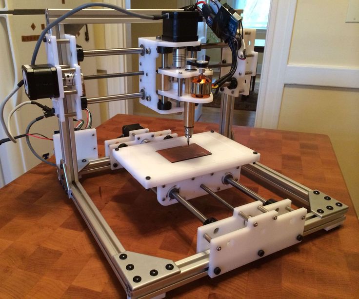
In the case of 3D printers, they use a heated platform to help adhere the object to the print surface. nine0008
Tools
VMC threadingCNC machines are versatile machines that allow you to change cutting tools to perform different types of cuts with different sizes and finishes.
3D printers lack this flexibility, and the printed object has the same resolution with a constant layer thickness throughout the print.
Accuracy and reproducibility
CNC machines can achieve higher precision than 3D printers because of the way they work. nine0008
The rigid frame of the CNC machine provides high repeatability with minimal vibration, making it suitable for high volume production where multiple items with the same dimensional accuracy are required.
On the other hand, 3D printers melt and print material layer by layer, causing the printed parts to be subject to slight dimensional inaccuracies.
Surface quality
3D printed plastic part (left) and CNC plastic part (right) In terms of surface quality, CNC is better than 3D printing. This is due to the wide range of tools used by the CNC.
With various tools such as ball end mill, end mill, sanding belt, etc., the CNC can produce workpieces with high surface quality.
The layering process of 3D printers leaves behind a rough surface texture on the workpiece.
Today, 3D printed parts are treated with surface finishing methods such as painting, powder coating, electroplating, etc. to achieve a smooth surface. nine0008
Part strength and stability
Compared to 3D printing, CNC machining allows parts to be produced with tighter tolerances and greater strength.
CNC machines have a tolerance of ±0.025mm, while advanced 3D printing techniques such as direct metal laser sintering (DMLS) can only achieve a tolerance of around ±0.1mm.
Also, because the CNC uses subtractive manufacturing methods to make the part from a block of material, it does not lose the original strength of the material. nine0008
The 3D printer adds layers of material on top of each other that are fused together to form the final product.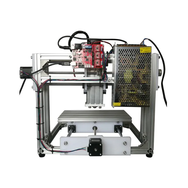 This reduces the overall strength of the part, making it prone to breakage.
The minimum line thickness that a modern 3D printer can achieve is 0.4 mm.
Costs
CNC machines are comparatively more expensive than a 3D printer with the same work area.
In addition, the need for various accessories such as coolant supply system, special cutting tools, etc., further increases the maintenance cost of CNC machines. nine0008
For small prototyping businesses, a 3D printer is a cost-effective option as it allows prototyping without the need for expensive equipment.
CNC and 3D Printing Basics
Additive and Subtractive Manufacturing
Additive ManufacturingAdditive Manufacturing is a technique that involves adding material layer by layer to produce a desired part or object. For example, 3D printers work on this principle. nine0008
This method is used for rapid prototyping of parts, production of complex parts and creation of customized products.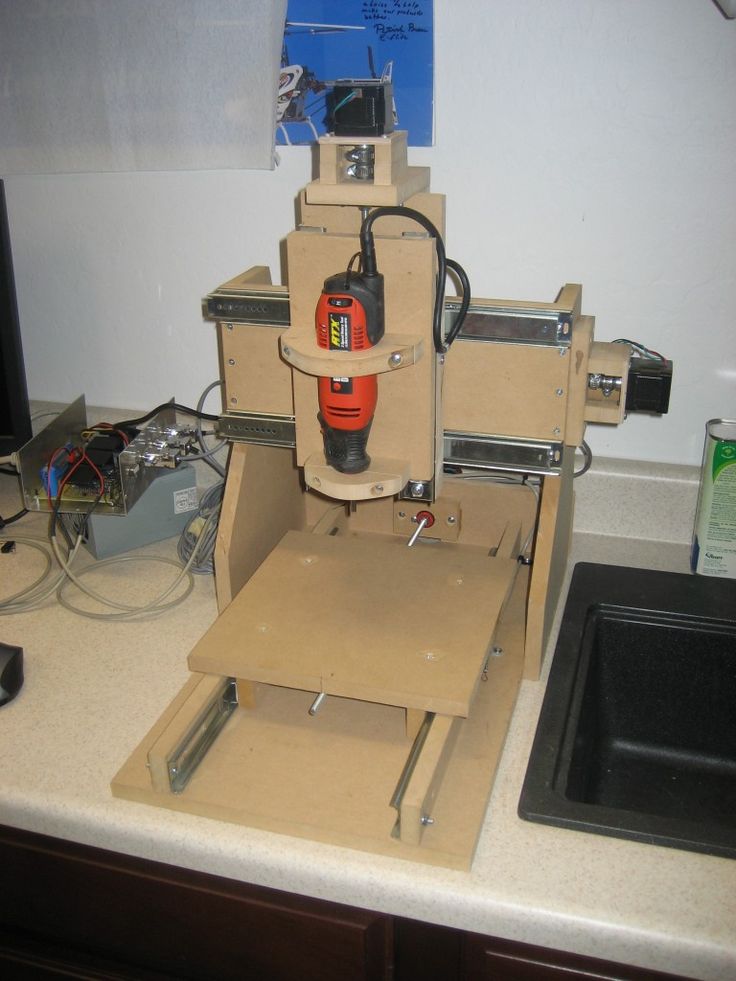
The Subtractive Manufacturing process removes material layer by layer from a blank block to create an object.
This is done with cutting tools and machines such as lathes, milling machines.
What is a CNC machine?
Various types of CNC machinesA CNC machine is a computer-controlled tool that can be used for various processing operations such as cutting, shaping and shaping various materials. nine0008
These machines typically have three axes of motion and can produce complex shapes from materials such as metal, wood, plastic, etc.
Numerical control technology has been used in manufacturing for decades. This allows machines to be programmed to perform complex operations automatically.
It is now an integral part of the production process in many industries and can be found in various types of machines. nine0008
Some of the common CNC machines include CNC milling machines, CNC lathes, laser cutters, plasma cutters, electrical discharge machines (EDM), grinders, etc.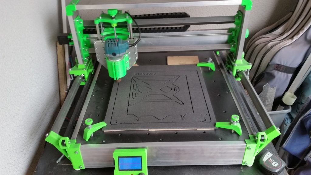
What is a 3D printer?
3D printing vase with Snapmaker 2.03D printer is a type of automated machine that follows the principle of additive manufacturing and uses numerical control technology to produce the desired part from a CAD file.
These machines create 3D objects by laying successive layers of material on a build plate until the object is complete. nine0008
The most common type of 3D printer is Fused Deposition Modeling (FDM) printers, which work by extruding thin filaments of heated plastic, metal, or other materials that cool and solidify after being deposited.
Practical application of 3D printing and CNC machining
Practical application of 3D printing and CNC machining depends on the material you plan to work with, the type of part you want to produce, the quantity and speed at which you want to make them.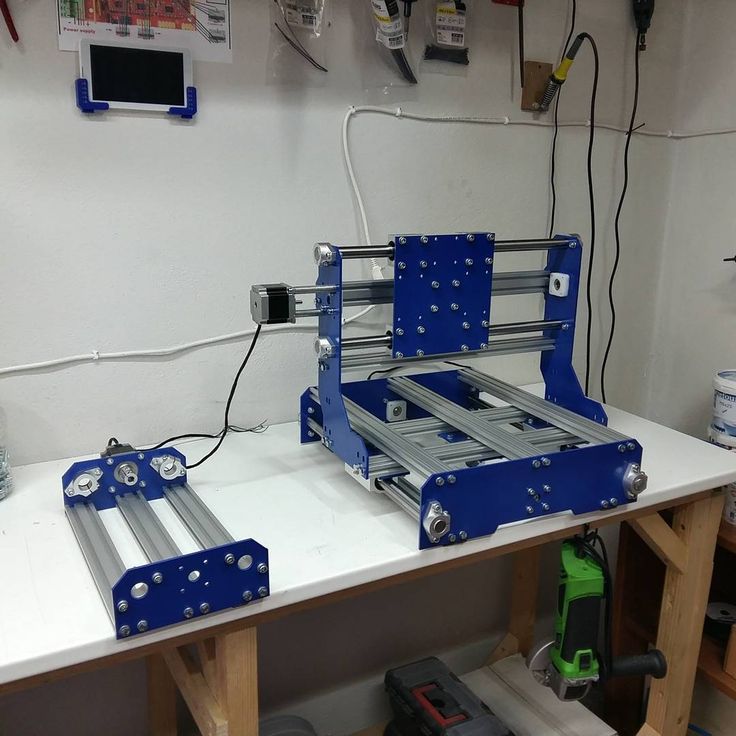 nine0008
The type of material you plan to use
The materials most commonly used for 3D printing are plastics, metals, and some biomaterials such as sugar or wood pulp.
3D printers can also use other materials such as ceramics and concrete, but these materials are less common because they take more time and effort to produce than plastics or metals.
By comparison, CNC machines can cut and mill almost any material. Some popular CNC machining materials are metals, wood, and plastics. nine0378 Common types of plastic and metal materials used in 3D printers.
Which is better for making metal parts?
CNC milling machine processes metal workpiece. TheCNC machine is best for making metal parts because its rigid structure and transmission provide higher precision and accuracy than a 3D printer.
In addition, it allows the production of metal parts with higher tolerances compared to 3D printers. nine0008
What about plastic?
Both 3D printing and CNC machining are equally good for making plastic parts.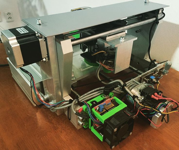 The best option depends on the amount of detail you plan to make.
How many parts do you plan to make?
CNCs are better suited for machining large quantities of parts because they have higher repeatability.
If you are using 3D printing techniques to make similar parts, it may be more expensive than CNC machining. nine0008
This is because 3D printers take more time and effort to complete a job, while CNC machines can produce many parts at once or in cycles with little effort.
3D printing is ideal for prototyping when you need to make fewer parts (less than 10), whereas if you want to make more parts, it is better to consider using a CNC machine.
For larger objects, consider CNC machining methods such as casting or injection molding as they are cost effective when producing parts in large quantities. nine0008
Which is better for prototyping?
While both 3D printers and CNC machines can produce custom parts or prototypes, 3D printers are much more efficient because they allow you to make multiple changes at a lower cost.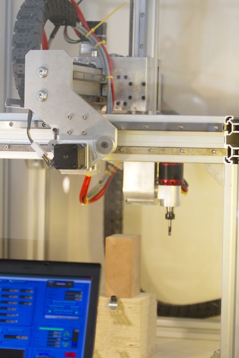
Therefore, various industries such as engineering, architecture, design and medicine use 3D printers for prototyping.
Will 3D printing replace CNC machines?
In a short period of existence, 3D printers have been able to partially replace the CNC used in the fields of medicine, architecture, product design, etc. nine0008
With controlled spray printing technology and the ability to create complex shapes, 3D printers are now increasingly being used to create architectural models and real structures.
Medical prostheses such as dental implants, orthopedics, etc. are now using 3D printers to produce various parts like never before.
These manufacturing shifts seen in these industries are a prime example of how 3D printers could replace CNC in the near future. nine0008
Although 3D printers can replace CNC in many areas, they still cannot replace CNC when it comes to producing parts with high precision and tight tolerances.
In addition, the wide range of materials that the CNC can work with is a huge advantage of the CNC over 3D printers.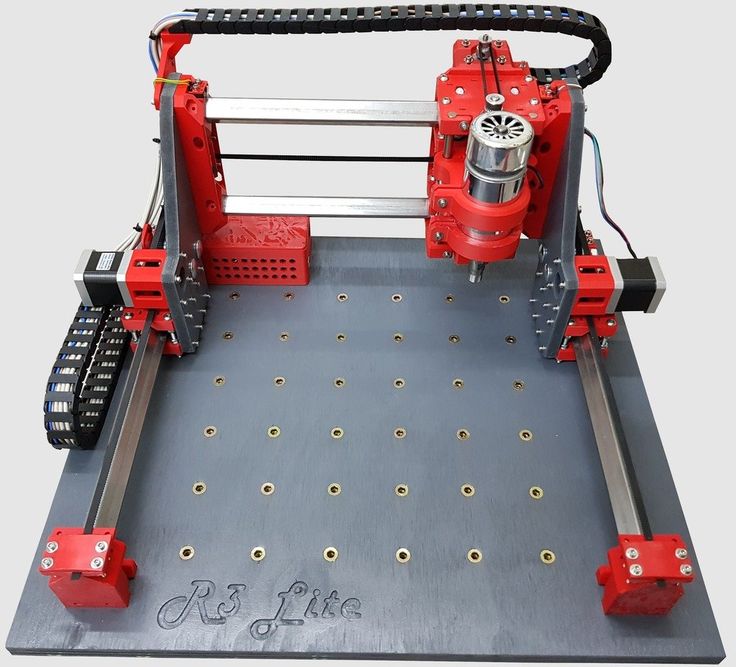
In short, CNC is here to stay. Although they have lost their importance in some industries, they are the most commonly used machines in the manufacturing industry. nine0008
It is difficult to say whether one will completely replace the other. But in the future, they will be used together to create complex molds and prototypes.
In fact, CNC hybrid 3D printers are currently used in some industries.
Traditionally, printing and cutting were done on separate machines, but these hybrid printers or CNCs can do both tasks on the same machine.
Final thoughts - which is better?
Since the introduction of 3D printing into the manufacturing industry, it has taken over some of the work of CNC, but they could not take over all. nine0008
Much of the work is still done on CNC machines such as milling, turning, milling and grinding machines.
CNC and 3D printers are part of the puzzle. They both have their places, and both are needed to complete it.


