Diy 3d printer reddit
Reddit Archives - Perfect 3D Printing Filament
Auto Added by WPeMatico
Posted on
We didn’t have a lot of NERF guns in the house growing up, but I do remember one specific NERF incident when I was older. I was home from college for winter break, and my family and I were stuck inside due to a snow emergency. We were getting restless and sick of watching TV, when someone – my mom, maybe – randomly picked up a NERF dart gun from behind her chair, aimed it at the map of Michigan hanging over the couch across the room, and fired. The game quickly evolved into seeing who could get the dart to stick the closest to where we vacationed each summer, and we all forgot we’d been bored.
Just like using 3D printing to increase the fun of LEGOs, so too can the technology be put to work with NERF weapons. NERF modding is the practice of adding hands-on modifications to your NERF guns, so their capabilities are enhanced.
“NERF blasters aren’t just for pre-pubescent boys — the resurgence of NERF is real and it’s happening now,” a Manual post states.
“Grown men are dipping back into the hobby and making hands-on modifications that increase the range and speed of the toys.”
3D Printed Hades Pump Grip, $12 on Out of Darts
In the post, Luke Goodman, referred to there as “the surgeon general of NERF modifications,” describes the basics of modding a NERF Hammershot blaster gun. The former filmmaker wrote a popular book about Nerf modding, and also runs an online shop and NERF modification YouTube Channel called Out of Darts.
Goodman came up with some novel mods, like an air blaster that holds 1,200 rounds and shoots 15 rounds per second, and purchased a 3D printer so he could make his own modification parts. It’s now his full-time gig.
“There’s nothing better than taking something into your own hands and improving it — taking something old and making it new,” Goodman said. “For both kids and adults, getting them off video games, working with their hands, and interacting with the community can happen through NERF.”
Luke Goodman with modified NERF gun (Credit: Luke Goodman)
Reddit user Pballwiz24 posted about his 3D printed hobby-grade NERF blasters, which look like they stepped right out of the 1990s. An appreciative person said they were “still amazed how much 3D printing has revolutionized homemade nerf guns and the nerf community as a whole,” and Pballwiz24 agreed, writing “It really helped launch the hobby to a whole new level.”
Another user wanted to know if the darts had to be cut down, and what was used for springs.
Pballwiz24
“Yeah they are cut to 39mm,” Pballwiz24 replied. “They use brushed motors with flywheels on them to compress and “throw” the dart out.
”
He was asked if the model was available on Thingiverse, and while the answer was no, he did state that several of his other models were there under the search term “cowabunga.” I checked it out, and the first one I found was the Cowabunga! Foam Dart Blaster by user radblasters, which contains detailed instructions on how to 3D print your own.
Cowabunga! Foam Dart Blaster
“The key feature of this design is the fact that it uses a smaller solenoid than most other solenoid builds. The Solenoid I designed this around is about half the size of the 35mm ones that are currently popular, but it functions exactly as needed (at only 15mm stroke),” it says in the description.
“Other than that feature, this is basically a primary blaster crammed into the smallest form factor I could create. Fully built, this can get 130-140 FPS on 4x Honeybadger motors…and it can be select fire too!”
There are plenty of other NERF mod designs on Thingiverse as well, such as sights, scopes, barrel extensions, magazines and dart holders, and even this cool NERF-compatible Grappling Hook.
“Printed without raft/supports. The first 5-6 layers look a little rough for lack of supports but it builds just fine,” Thingiverse user hewmart wrote. “I printed: 100% infill .2mm layer height 2 shells 60mm/s travel but these settings are probably changeable.”
If you think you’d like to try 3D printing a NERF mod, but are a little intimidated by the process and don’t know where to start, fear not – you can find Nerf Mods: a Beginner’s Guide on Instructables, which introduces readers “to the vast world of Nerf gun modifications” with instructions that are easy to understand.
“Beginners can be easily repelled from the world of Nerf gun modding by seeing a modification “write-up” that seems complicated. Many modification write-ups do seem confusing at first. However, modding a Nerf gun isn’t very hard–It simply takes knowledge of how a Nerf gun works and how a mod should be executed. With this knowledge, modifying Nerf guns is quite simple,” the post states.
While the instructable doesn’t actually mention 3D printing, it’s still a very helpful guide, with details on a variety of different mods and the differences between NERF spring guns and pump guns. You can check out one of the YouTube videos in this article for help with some cool 3D printed NERF mods.
Have you ever 3D printed a NERF mod? Tell us about it! Discuss this story and other 3D printing topics at 3DPrintBoard.com or share your thoughts in the Facebook comments below.
The post Niche Made: Modding NERF Guns With 3D Printing appeared first on 3DPrint.com | The Voice of 3D Printing / Additive Manufacturing.
Posted on
I always enjoy a good 3D printed DIY project, whether it’s truly helpful or just for fun. These projects are even cooler when you add Legos into the mix, like Reddit user DIY_Maxwell did. He posted about his work using 3D printing, Arduino, Raspberry Pi, and Lego bricks to make an open source, motorized microscope. But, the microscope itself is not fully 3D printed – instead, the body was built with Lego bricks and some 3D printed components. What makes this project more awesome is the stop motion-style video he made showing the various parts of the project and how they all fit together to make a working microscope.
BUILD YOUR OWN MOTORIZED MICROSCOPE using 3D-printing, Lego bricks, Arduino and Raspberry Pi… all design files, source codes and detailed instructions are provided open-source.
from r/3Dprinting
“I wanted to have a modular microscope, something I can easily modify for transmitted-light, reflected-light, cross-section, etc. My early prototypes did not have Legos, as I started making my own interlocking pieces, I realized that I was in fact printing lego-like designs, I thought buying legos would be less of an effort,” he wrote on Reddit when asked why he didn’t 3D print all the parts. “Then I found out about these “sliding” lego pieces, which are very precise for linear actuators. The other advantage is that, if I want to change the height of the camera let’s say, I simply add more bricks, it’s convenient.”
DIY_maxwell used FreeCAD to design the 3D printed microscope parts, which were fabricated on an Ender 3 system. All of the source codes and design files have been provided open source on GitHub, along with detailed step-by-step instructions on how to make your own.
Before you jump right in, do you know what exactly a motorized microscope does when compared to a regular microscope? DIY_maxwell explained that, at least for him, it needed to be able to tilt in order to take photos, from an angle, of “highly reflective surfaces (semiconductor chips),” and that it should quickly adjust the focus and magnification, and position of the sample.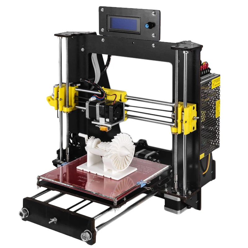
“The microscope has a simple operation principle based on changing the magnification and the focus by adjusting the relative distances between a camera, a single objective lens and a sample. Briefly, two linear stages with stepper motors are used to adjust these distances for a continuous and wide magnification range,” the GitHub instructions state. “Four additional stepper motors tilt the camera module and change the X-Y position and rotation of the sample. A uniform light source illuminates the sample either from an angle (reflected light) or from the bottom of the sample (transmitted light).”
The main components of this modular, motorized microscope include a Raspberry Pi system, an 8 MegaPixel camera, six stepper motors, a keyboard or joystick for variable speed control, uniform illumination, and obviously plenty of Lego bricks.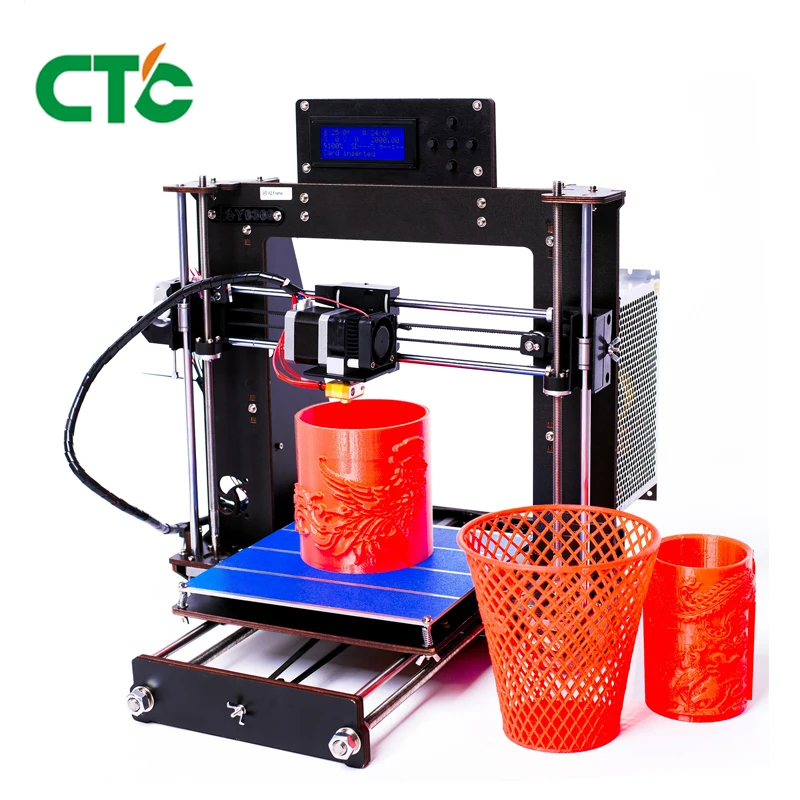 Depending on the specific features and electronics vendors used, the whole thing costs between $200-$400, and once you have all the parts in front of you, should only take a couple of hours to assemble.
The main body was built with individually-purchased Lego bricks, and DIY_maxwell designed custom actuators and 3D printed them, rather than using available motors and gears from LEGO Technic.
“This approach not only lowered the cost of the microscope but also gave me some flexibility in the design and implementation of precise linear and rotary actuators. In principle, the whole structure could be 3D-printed without using any LEGO parts but that would be less modular and more time consuming,” he writes in GitHub.
In addition, 3D printing offers you the flexibility of quickly changing the design for maximum optimization if and when it’s needed.
“If the parts do not match well, some minor modification in the original design file (e.
g. enlarging the holes matching to LEGO studs) or polishing/drilling may be required,” he explained.
The contents of the motorized microscope are as follows:
- Linear Actuators
- Camera Module
- Rotary Stage
- Illumination
- Tilt Mechanism
- Electronics
- Final Assembly
- Software
You can find detailed instructions, images, slicer settings, tips, and more on GitHub, and a longer version of the assembly video can be viewed here.
Several other Reddit users who routinely use microscopes related how impressed they were about the project; a geologist mentioned that “starting price can be anywhere between $500 to $1000 for something with that kind of quality” when DIY_maxwell said that his microscope could “easily resolve 10um features.” A pathologist expressed excitement about “a modular system to motorize common non motorized microscopes (Leica, Olympus, etc.).” While the compliment was appreciated by the maker, it was noted that “this microscope is not meant to replace a lab microscope used for medical assessment.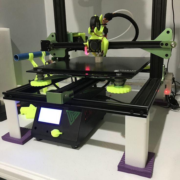 No dark-field, no fluorescence, no aperture control, it suffers from chromatic aberration and other optical effects at high magnification, etc.”
“I hope this prototype persuades other DIY-enthusiasts to develop new designs of microscopes.”
If you’re interested in using 3D printing to make your own microscope, you can check out all of the relevant information on GitHub to build this one, or check out the OpenFlexture Microscope project on Wikifactory. This was created as “part of the Waterscope initiative, which by allowing for fast and affordable on-site bacterial testing of the water quality in developing regions of the world, is helping to cope with the diseases caused by bad quality water drinking.”
OpenFlexure Microscope
The OpenFlexure can be built in the classroom and used as an education tool for both students and teachers. Because the 3D printed microscope stage uses plastic flexures, the motion is free from friction and vibration, and the four-bar linkages in the stage can be 3D printed in a single job with no support material.
You can find other open source 3D printable microscopes on Thingiverse as well; happy making!
Discuss this and other 3D printing topics at 3DPrintBoard.com or share your thoughts below.
The post Build Your Own 3D Printed Open Source Motorized Microscope appeared first on 3DPrint.com | The Voice of 3D Printing / Additive Manufacturing.
Posted on
In this week’s 3D Printing News Briefs, we’re talking about partnerships, new software and buildings, and a neat 3D printed miniature. Together, Evolve Additive Solutions and Evonik are developing materials for the STEP process, while Awexim has partnered with Farsoon in an exclusive sales agreement, and SHINING 3D and 3D Systems released Geomagic Essentials. Oerlikon inaugurated its new R&D and production facility, and a Reddit user posted video of a miniature 3D printed steering wheel that fits on a video game controller.
Evonik and Evolve Partnering to Develop 3D Printing Materials
A little over a year ago, Stratasys spinoff company Evolve Additive Solutions emerged from stealth with its production-scale additive manufacturing STEP (selective thermoplastic electrophotographic process) solution.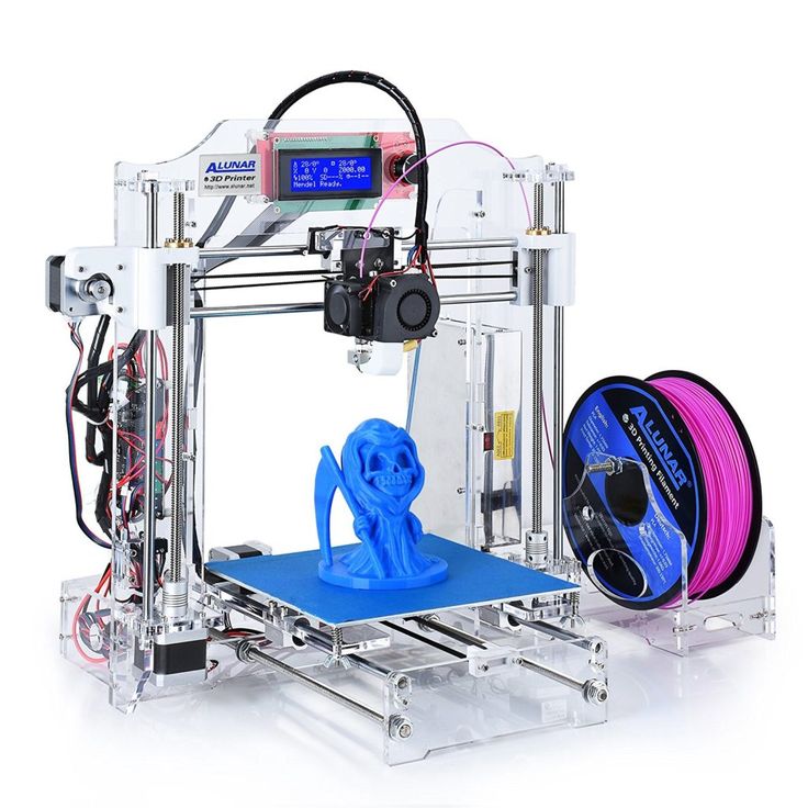 Now, the company is partnering up with the Evonik Corporation, a leading specialty chemicals company, in a joint development agreement to formulate the thermoplastic 3D printing materials for STEP solutions. Initial efforts will be focused on polyamide 12, PEBA, transparent polyamide, and polymer for the polyamide 6 series, and the two companies also plan to create a wider range of production materials for STEP users in the future.
“Evolve’s entirely new technology approach will allow us to expand the range of applications of our high-performance powder materials, which are produced through a unique production process,” said Thomas Grosse-Puppendahl, the Head of the Additive Manufacturing Innovation Growth Field at Evonik. “With more than 20 years of experience in 3D printing, we will also develop a wider range of customized powder formulations to unlock the full potential of the STEP technology.”
Farsoon and Awexim Sign Exclusive Sales Agreement
Another 3D printing partnership has Farsoon Europe GmbH, which is located in Stuttgart, signing an Exclusive Sales Agreement with Warsaw-based Awexim, which was founded in 1991 as a technical consulting and cutting tools supplier.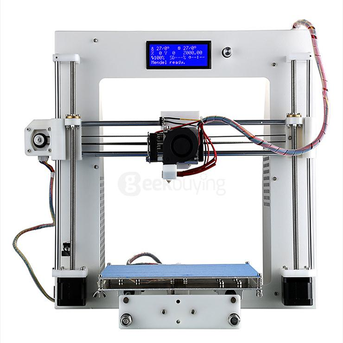 Awexim’s 3D printing adoption as an official Farsoon Europe sales agent will support Poland’s industrialization of 3D printing with Farsoon’s Open Laser Sintering Systems.
“Farsoon’s strength in industrial Laser Sintering Systems, ideally supports our strategy to enter into the 3D Printing market. We support industrial customers in Poland for almost 30 years with top quality tools, machine tools and especially top quality technical and customer service. We are glad to start cooperation with such solid partner as Farsoon, whose approach and vision is similar to ours,” said Andrzej Wodziński, the Managing Director of Awexim. “This cooperation opens huge possibilities to bring even more solutions for our customers on solving their needs. 3D printing is a future of industry, and we are sure, that connection of Farsoon and our team will have big influence on this industry in Poland.”
SHINING 3D and 3D Systems to Deliver Geomagic Essentials
Chinese company SHINING 3D recently announced that it has partnered up with 3D Systems to launch a new cost-effective scan-to-CAD solution.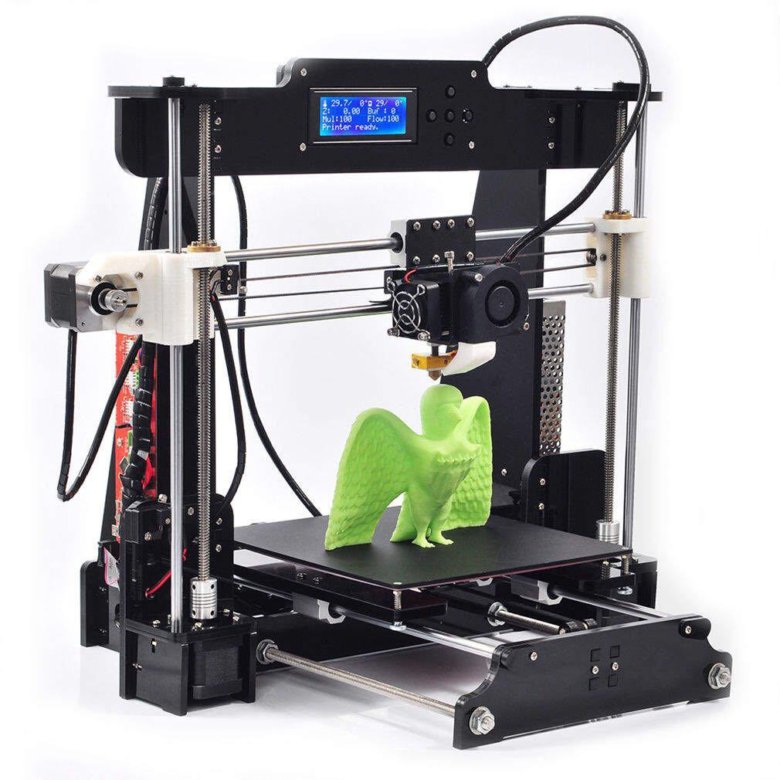 The two released Geomagic Essentials on the market as a bundled offering along with SHINING 3D’s most recent handheld, multi-functional 3D scanner: the Einscan Pro 2X series.
The Einscan Pro 2X and 2X Plus are lightweight and compact, with faster scanning speeds and higher accuracy. The new Geomagic Essentials bundled offer only increases these capabilities, as the solution is perfect for downstream reverse engineering and scan-to-print applications. While many CAD software programs are limited in terms of what they can do in processing, Geomagic Essentials makes the scan data compatible with native CAD workflows, so designers wanting to integrate part design and 3D scan data can do so with ease.
Oerlikon Inaugurates New R&D and Production Facility
Technology company Oerlikon is based in Switzerland, but it has 170 locations in nearly 40 different countries, including the US. The company provides surface solutions, equipment, and materials processing, and as part of its continuing growth strategy here, recently celebrated the opening of its new $55 million, state-of-the-art Innovation Hub & Advanced Component Production facility in Huntersville, North Carolina.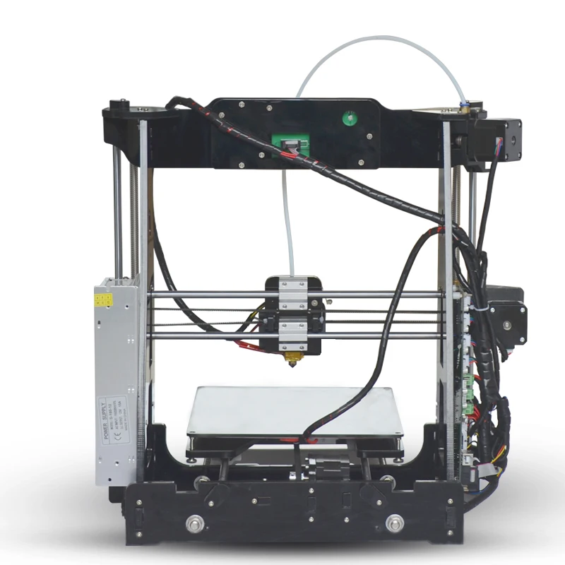 This is Oerlikon’s second location in the state, and the 125,000 sq ft, fully functional facility employs about 60 people and will continue to gradually add jobs as the business continues to expand.
“We are already working with customers in the aerospace, automotive, energy and medical industries in the US, and we anticipate continued growth in those sectors, as well as in others. We believe that additive manufacturing can transform production in many industries, and we are excited that our presence here in North Carolina allows us to better demonstrate those possibilities to our customers,” said Dr. Sven Hicken, Head of Oerlikon’s Additive Manufacturing business.
State and federal officials spoke at the inauguration event, which was attended by employees and their families, in addition to business leaders and customers. Oerlikon presented a local robotics club with a check at the event in order to begin growing collaborations with academic institutions and show support for STEM learning.
Oerlikon Huntersville Event
We had a lot of fun last week opening our new Innovation & Proctuction Hub in Huntersville, NC. Check out what happened on the big day! #OerlikonUSA #OerlikonAM
Gepostet von Oerlikon Group am Freitag, 7. Juni 2019
3D Printed Steering Wheel
Reddit user Malespams recently posted a video of a 3D printed steering wheel in action, but not one for a regular-sized car…or even a car at all, actually. No, this miniature green wheel is made to attach to the controller for a video game system, like XBox, to make it easier and more natural to play racing games. However, not everyone who commented on the video thought that the 3D printed mod would make these games easier. One person said that it would offer “zero control” during play, and another noted that it covered the controller’s right stick and would make it hard to press any buttons,
“I have one, but while it’s a fun concept it covers the dpad so if you’re playing horizon you can’t access Anna m.
Sometimes it hits the clutch and messes me up,” user 3202 people wrote. “It’s sometimes fun and I could see people having fun if they got used to it.”
If you’re interested in making your own game controller racing mod, check out this Thingiverse link.
Discuss these stories and other 3D printing topics at 3DPrintBoard.com or share your thoughts in the Facebook comments below.
Posted on
In today’s 3D Printing News Briefs, euspen plans to hold a Special Interest Group meeting in September centered around additive manufacturing, and an adjunct professor completed a comparison between a small SLS 3D printer and a large one. Moving on to interesting 3D printing projects, an artist teamed up with Mimaki to use full-color 3D printing to make a stage prop, a reddit user created an anti-cat button for an Xbox system, and an imgur user created a modular 3D printed fashion system.
euspen to Hold Special Interest Group Meeting on AM
The European Society for Precision Engineering and Nanotechnology (euspen) will be addressing the factors which are influencing an uptake of the use of additive manufacturing as a production technology at a Special Interest Group (SIG) meeting in September.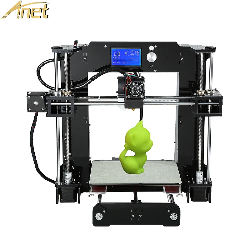 The meeting, which will be co-hosted by the American Society of Precision Engineering (ASPE), will analyze the barriers to, and the opportunities for, the adoption of AM in production. It will be held from September 16-18 at the École Centrale de Nantes in France.
At the AM SIG meeting, issues that are, as euspen put it, “critical to the viability of AM as a production technology,” will be addressed. The co-chairs of the meeting are Professor Richard Leach from the University of Nottingham and Dr. John Taylor from the University of North Carolina at Charlotte. Local hosts and the organizing committee include Professor Alain Bernard from Centrale Nantes, Dr. David Bue Pedersen from the Technical University of Denmark, Professor Leach, and Dr. Taylor.
Comparison of Small and Large SLS 3D Printers
3D printers are often used in educational settings these days. Piotr Dudek, an adjunct professor at the AGH University of Science and Technology in Poland, runs a 3D printing lab at the school that both students and researchers frequent.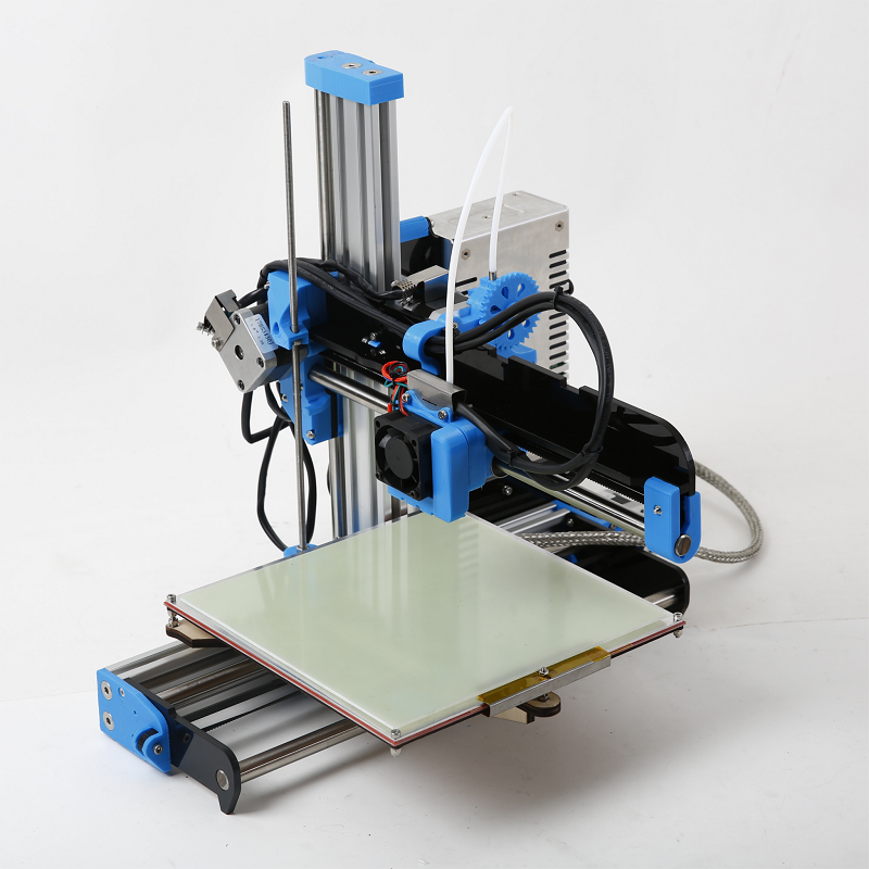 While many technologies are used in the lab, SLS is the one that most interests Dudek, who decided to compare a big SLS system from EOS with the smaller Sinterit Lisa.
“We are using the big EOS SLS 3D printer for a long time and we wanted to compare it with Sinterit Lisa, check the possibilities of it. In SLS technology every detail matters. The temperature of the printing chamber, powder distribution system, heating or laser moving mechanism are very precise and important features. We wanted to test if Sinterit’s device is the valuable solution,” Dudek stated.
Larger 3D printers obviously have higher print volumes, but the down sides include difficult calibration, specialized training, and higher costs. In addition, it’s easy to mess up the calibration of a large 3D printer during transport. The Lisa 3D printer uses a gantry system, which comes pre-calibrated to save time, and it also uses less material, which means less money. The desktop printer is also much more student-friendly, making it the better choice for 3D printing labs like the one Professor Dudek runs.
Full-Color 3D Printed Stage Prop
A few months ago, 3DPrint.com heard from 3D printing specialist and Post Digital Artist Taketo Kobayashi, from the Ultra Modelers community, about an art exhibit in Japan that he helped organize which featured colorful, 3D printed works created on the Mimaki 3DUJ-553 full-color 3D printer. Recently, he reached out to us again with news of his latest Mimaki Engineering collaboration – a stage prop for the Japanese artist Saori Kanda, who performed with techno/trance band Shpongle at the Red Rocks Amphitheater in Colorado.
“It is a artwork,” Kobayashi told 3DPrint.com, “but also a utilization of full color 3D printing to entertainment field.”
The “Shpongle Mask,” which took 28 hours to print and mixed in Asian details, was worn onstage by Kanda as she performed her painting live with the band.
3D Printed Anti-Cat Xbox Button
reddit user Mbiggz was getting sick of their cat turning off the touch-sensitive button on the Xbox console while it was in use, which I can understand, having two cats of my own. So Mbiggz came up with the perfect solution – a 3D printed cover for the button. The design can be found on the maker’s Tinkercad account, as Mbiggz originally made the design for a Digital 3D class.
“Adhesive goes on the back part (it is labeled in the print). I’m a newcomer in terms of this so it’s not perfect,” Mbiggz wrote on Tinkercad. “Also, the door doesn’t open all the way, so you can fix it so that it does if you want to (even though it doesn’t really matter, there’s not really a need for it to open it all the way).”
3D Printed Modular Fashion System
hunter62610, a young imgur user, designed and 3D printed a Lego-like modular fabric system, which was featured in his school’s fashion show. He made two dresses that are made with a 3D printed prototype fabric pattern called Escher, which was designed to be “put together and taken apart” hundreds of times. It took him just two weeks to make the material, which the two young ladies who modeled the dresses said was fairly comfortable.
“The idea of the system is that theoretically, one could buy a fashion catalog filled with designs, and say 5000 links. Once could make every clothing item in the catalog, based on there needs. Perhaps that’s a pipe dream, but it’s a fun idea,” hunters62610 wrote.
“The Escher system is quite versatile. Each link acts like a free flowing Equilateral triangle, and has a male and female ball joint on each side. Every individual link is theoretically compatible with every other link. Special links are stored in the middle of this pouch that are really 3 merged links with a screw hole. If needed, these links can be used as elastic tie down points or buttons, if you screw in the buttons i made.
”
A Makerbot Replicator Plus was used to print the fabric links in unique, small panels.
Discuss these stories and other 3D printing topics at 3DPrintBoard.com or share your thoughts in the Facebook comments below.
Posted on
This year’s RAPID + TCT ended late last week at the Cobo Center in Detroit, so we’re again starting off today’s 3D Printing News Briefs with more news from the busy show floor. DyeMansion launched a new extended color series at RAPID, while 3D Systems made the announcement that its Figure 4 Modular is now available. Moving on, SLM Solutions just celebrated the grand opening of its new Shanghai application center. Finally, a Reddit user made an adorable miniature 3D printer.
RAPID 2019: DyeMansion’s New Colors
DyeMansion at RAPID 2019 [Image: Sarah Saunders]
Munich startup DyeMansion, a leader in finishing and coloring solutions for 3D printing, launched its new ColorsX extended color series for end-use products at RAPID last week, in order to continue helping its customers achieve the perfect finish for all of their applications. Automotive ColorsX and Neon ColorsX are the first solutions under the startup’s X Colors for X Industries premise, with more to follow in the future. The automotive color line has improved light and heat resistance for better 3D printed polyamide components and interior car parts, and features Automotive BlackX, which has a less saturated black tone than DyeMansion’s basic DM Black 01 and was created according to ISO EN 105 B06 method 3’s hot irradiation standards. The luminous neon color line includes GreenX, YellowX, OrangeX and PinkX to help create striking end-use products. Both of these new color lines are compatible with DyeMansion’s PolyShot Surfacing (PSS) and VaporFuse Surfacing (VFS).
“Some of our earliest customers who made use of DyeMansion Print-to-Product technologies for serial production are from the Automotive and Lifestyle industries,” explained Kai Witter, DyeMansion’s Chief Customer Officer. “While working closely with our customers, joint strategies are always about creating even more value to their businesses.
So, I feel very delighted to now offer additional value creating products. Automotive and Neon ColorsX are only the beginning of providing more specific industry offers.”
Once DyeMansion decided to launch its ColorsX series, it also named the coloring process it established back in 2015: DeepDye Coloring (DDC), which can be easily controlled and traced through integrated RFID technology and offers a limitless choice of custom colors.
RAPID 2019: 3D Systems Announces General Availability of Figure 4 Modular
Also at RAPID last week, 3D Systems announced the general availability of its scalable Figure 4 Modular production platform. The flexible digital light printing (DLP) system has multiple configurations that can print parts with high surface quality, and allows manufacturers to iterate designs more quickly, as well as produce end-use parts without having to worry about a minimum order quantity.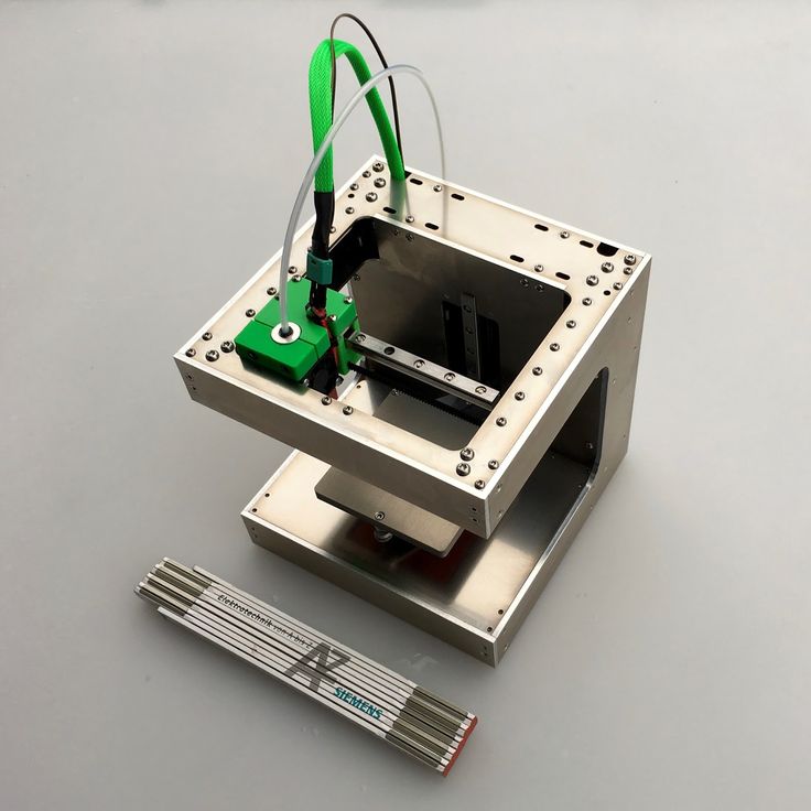 Three models make up the Figure 4 – Standalone, Production, and Modular – and several customers, such as D&K Engineering and Midwest Prototyping, are reaping the benefits. Additionally, 3D Systems also announced five new DLP and SLS materials, the first of which is the immediately available Figure 4 FLEX-BLK 10. The other new Figure 4 materials, such as TOUGH-BLK 20, MED-AMB 10, MED-WHT 10, and HI-TEMP-AMB 250, are expected to be available in Q3 and Q4 of 2019.
“The newest additions to our plastic 3D printing portfolio demonstrate our commitment to driving the adoption of digital manufacturing. With the industry’s first, truly scalable plastic production platform and our robust selection of materials, 3D Systems enables customers to rethink manufacturing and realize improved agility, reduced complexity, and lower overall total cost of operation,” said Vyomesh Joshi, the President and CEO of 3D Systems.
3D Systems also announced that its customers Rodin Cars (based in New Zealand) and North Carolina-based Stewart-Haas Racing are using its plastic and metal 3D printing solutions to improve the speed and performance of their cars.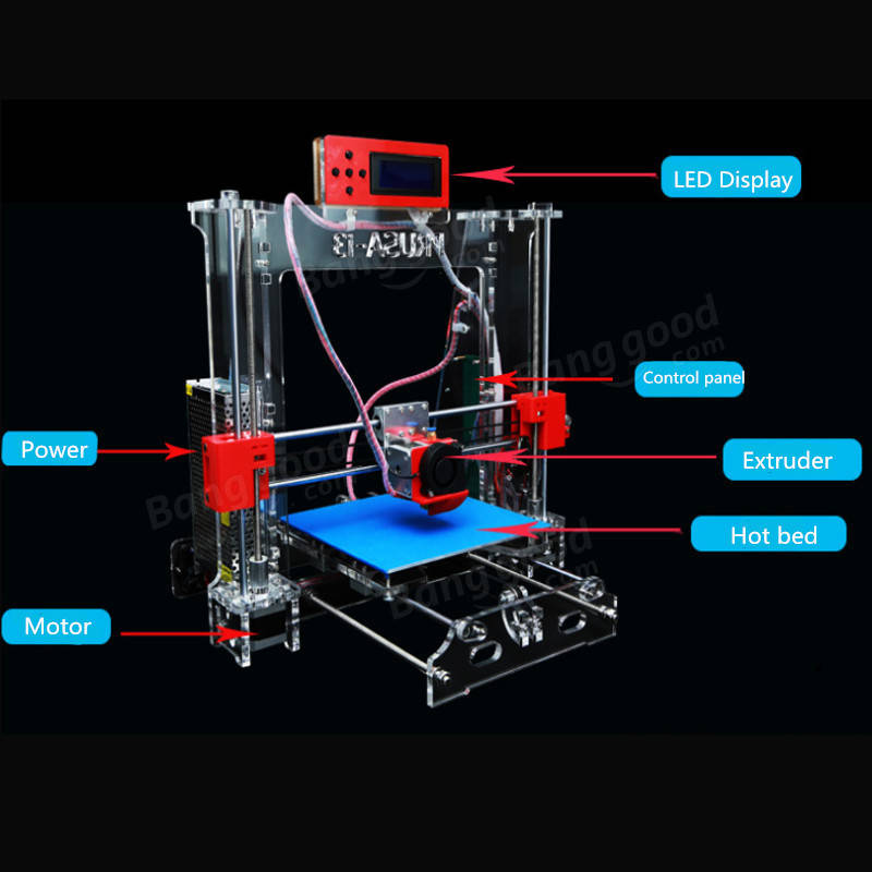
SLM Solutions Celebrates Opening of New Shanghai Application Center
The same year that SLM Solutions opened an applications and demonstration center in Germany, it also established Chinese operations in Shanghai. Earlier this week, the selective laser melting experts celebrated the grand opening of their expanded office facilities and application center in Shanghai, which will help the company continue to grow its presence on the Asian market. The new center has installed four SLM systems: one SLM 125, one SLM 500, and two SLM 280 printers. Additionally, the facility also has equipment to represent an SLM build’s supporting process chain, such as a metallurgical lab and post-processing capabilities. The grand opening included a tour through the new new customer service and application engineering center.
“As we continue to grow our Chinese team, the opening of our Shanghai Application Center is an important milestone in SLM Solutions’ development and indicates the confidence in the Chinese market,” stated Jerry Ma, General Manager of SLM Solutions (Shanghai) Co.
, Ltd. “As part of the global strategy for growth we have the capacity to more than double our number of employees and the equipment to support all Chinese users with the technological resources shared by our applications centers around the world. We can also provide high-quality, fast technical services to better promote the development of selective laser melting and create more value for customers.”
Mini 3D Printed 3D Printer
A reddit and imgur user by the name of “Mega Andy” used 3D printed parts and DVD drive motors to make his own miniature 3D printer. And by miniature, I mean that he used a banana for scale, which was taller than the 3D printed 3D printer itself! It’s a really interesting project – the device runs Marlin, and features a glass bed and an E3D V6 hotend. The black and gold parts of the mini 3D printer were made out of PLA material, while PETG was used to make teeth for the leadscrews. Speaking of this, Mega Andy said that the printer is “fairly unreliable” because it easily ruins the teeth that guide the device on the leadscrew.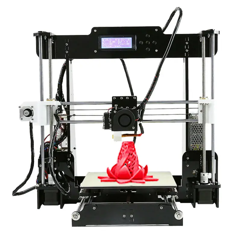 Additionally, he’s also working to improve and lengthen the Z axis due to binding problems. Mega Andy released the STLs onto Thingiverse so others could try to make their own versions of the miniature 3D printed 3D printer…say that five times fast.
“So this project is nothing new, people have made 3d printers, CNC, engravers before using this hardware. What I wanted to do differently with this is have a designed 3D printed frame to hopefully fit standard parts. Instead of mounting full metal dvd drive assembly’s together and look like a DIY project I wanted a something that could be more compact and neat,” Mega Andy wrote on Thingiverse.
“This project is not for everyone and would only recommend to someone with a decent knowledge of 3d printers, basic soldering and lots of patience. Also some fiddling was needed to get the right amount of tension on the leadscrew, this bit is a massive pain but hopefully no one else needs to go through quite as much issues as i did with this bit.
They will wear out though and a 3d printer will be needed to print new parts for it when they inevitable wear out.”
Discuss these stories and other 3D printing topics at 3DPrintBoard.com or share your thoughts in the Facebook comments below.
Posted on
Lulzbot, the open-source brand of the FDM 3D printers from Colorado-based manufacturer Aleph Objects, has hinted the development of an stereolithography (SLA) 3D printer in its latest newsletter. The newsletter heading states: “Wash Away Your 3D Printing Preconceptions: We’ve got the cure for the common printer—our newest solution will be released this September! We’re laser focused on the […]
Build a Reddit Shower Thoughts Printer — Arduino
Skip to content
SearchProjects from Make: Magazine
- By Dylan Rush
- Time Required: 38 Hours
- Difficulty: Moderate
- Print this Project
With the press of a button, Thinking Man produces a random amusing thought from its onboard thermal printer.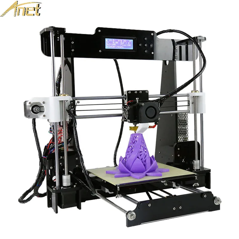 As it turns out, these thoughts are actually random post titles from Reddit’s popular subreddit Shower Thoughts that are downloaded over a Wi-Fi connection. The result is an objet d’art that can surprise you with its cleverness. It’s also a great project to explore using the Arduino to create an IoT device.
Putting the hardware together is straightforward. You can take these core electronics and turn just about any object into an IoT printer.
Because the entire response from Reddit is too large for the Arduino to store in memory, the microcontroller has to pick out the relevant data as it is received. The included source code does just that, and can be adapted to read data from anywhere on the internet or your home network.
An example of Shower Thoughts from Reddit.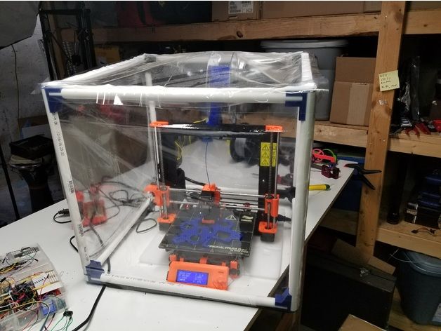
With a little tweaking, you can make your own Thinking Man produce jokes, headlines, weather reports, or class schedules.
Thinking Man came about when a collection of odd parts became ingredients for an interesting project. I think the thermal printer worked well because it’s a unique way to communicate, and these thoughtful yet childish ideas are just spilling out of its head. I hope Makers can use my ideas and code to create something that excites them.
Tagged ArduinoESP8266make49printerredditShower ThoughtsThermal Printerwi-fi
Dylan Rush
Dylan Rush is a hobbyist inventor and professional software developer. He seeks to create thought-provoking art through engineering.
When you buy through links on our site, we may earn an affiliate commission.
Cookie Settings
Our websites use cookies to improve your browsing experience. Some of these are essential for the basic functionalities of our websites. In addition, we use third-party cookies to help us analyze and understand usage. These will be stored in your browser only with your consent and you have the option to opt-out. Your choice here will be recorded for all Make.co Websites.
Allow Non-Necessary Cookies Allow Non-Necessary Cookies
Building a home 3D printer with your own hands: recommendations from personal experience
3D printing and assembly of 3D printers is my hobby and passion. Here I will not share detailed diagrams and drawings, there are more than enough of them on specialized resources. The main goal of this material is to tell you where to start, where to dig and how to avoid mistakes in the process of assembling a home 3D printer. Perhaps one of the readers will be inspired by applied engineering achievements.
Why do you need a 3D printer? Use cases
I first came across the idea of 3D printing back in the 90s when I was watching the Star Trek series. I remember how impressed I was by the moment when the heroes of the cult series printed the things they needed during their journey right on board their starship.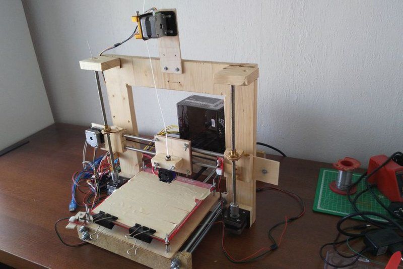 They printed anything: from shoes to tools. I thought it would be great someday to have such a thing too. Then it all seemed something incredible. Outside the window are the gloomy 90s, and the Nokia with a monochrome screen was the pinnacle of progress, accessible only to a select few.
Years passed, everything changed. Around 2010, the first working models of 3D printers began to appear on sale. Yesterday's fantasy has become a reality. However, the cost of such solutions, to put it mildly, discouraged. But the IT industry would not be itself without an inquisitive community, where there is an active exchange of knowledge and experience and who just let them dig into the brains and giblets of new hardware and software. So, drawings and diagrams of printers began to surface more and more often on the Web. Today, the most informative and voluminous resource on the topic of assembling 3D printers is RepRap - this is a huge knowledge base that contains detailed guides for creating a wide variety of models of these machines.
I assembled the first printer about five years ago. My personal motivation to build my own device is quite prosaic and based on several factors. Firstly, there was an opportunity to try to realize the old dream of having your own device, inspired by a fantasy series. The second factor is that sometimes it was necessary to repair some household items (for example, a baby stroller, car elements, household appliances and other small things), but the necessary parts could not be found. Well, the third aspect of the application is "near-working". On the printer, I make cases for various IoT devices that I assemble at home.
Agree, it is better to place your device based on Raspberry Pi or Arduino in an aesthetically pleasing "body", which is not a shame to put in an apartment or take to the office, than to organize components, for example, in a plastic bowl for food. And yes, you can print parts to build other printers :)
There are a lot of scenarios for using 3D printers.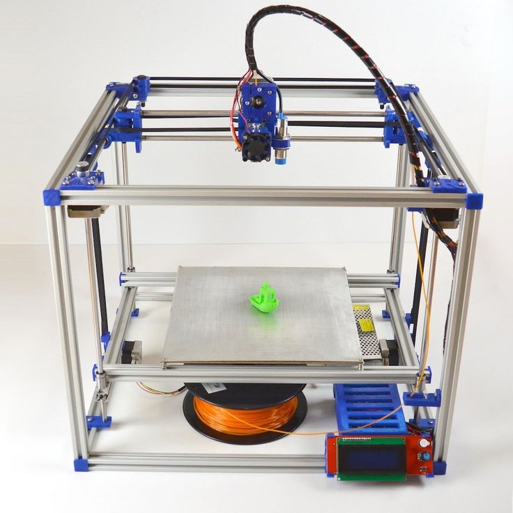 I think everyone can find something of their own.
A complex part in terms of drawing that I printed on my printer. Yes, it's just a figurine, but it has many small elements
Ready solution vs custom assembly
When a technology has been tested, its value in the market decreases markedly. The same thing happened in the world of 3D printers. If earlier a ready-made solution cost simply sky-high money, then today acquiring such a machine is more humane for the wallet, but nevertheless not the most affordable for an enthusiast. There are a number of solutions already assembled and ready for home use on the market, their price range ranges from $500-700 (not the best options) to infinity (adequate solutions start from a price tag of about $1000). Yes, there are options for $150, but we, for understandable, I hope, reasons, will not dwell on them.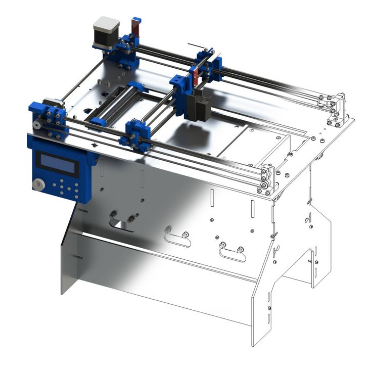
In short, there are three cases to consider a finished assembly:
- when you plan to print not much and rarely;
- when print accuracy is critical;
- you need to print molds for mass production of parts.
There are several obvious advantages to self-assembly. The first and most important is cost. Buying all the necessary components will cost you a maximum of a couple of hundred dollars. In return, you will receive a complete 3D printing solution with the quality of manufactured products acceptable for domestic needs. The second advantage is that by assembling the printer yourself, you will understand the principles of its design and operation. Believe me, this knowledge will be useful to you during the operation of even an expensive ready-made solution - any 3D printer needs to be serviced regularly, and it can be difficult to do this without understanding the basics.
The main disadvantage of assembly is the need for a large amount of time.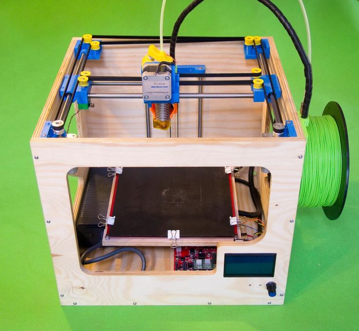 I spent about 150 hours on my first build.
What you need to assemble the printer yourself
The most important thing here is the presence of desire. As for any special skills, then, by and large, in order to assemble your first printer, the ability to solder or write code is not critical. Of course, understanding the basics of radio electronics and basic skills in the field of mechanics (that is, "straight hands") will greatly simplify the task and reduce the amount of time that needs to be spent on assembly.
Also, to start we need a mandatory set of parts:
- Extruder is the element that is directly responsible for printing, the print head. There are many options on the market, but for a budget build, I recommend the MK8. Of the minuses: it will not be possible to print with plastics that require high temperatures, there is noticeable overheating during intensive work, which can damage the element. If the budget allows, then you can look at MK10 - all the minuses are taken into account there.
- Processor board. The familiar Arduino Mega is well suited. I didn't notice any downsides to this solution, but you can spend a couple of dollars more and get something more powerful, with a reserve for the future.
- Control board. I'm using RAMPS 1.4 which works great with the Arduino Mega. A more expensive but more reliable board is Shield, which already combines a processor board and a control board. In modern realities, I recommend paying attention to it. In addition to it, you need to purchase at least 5 microstep stepper motor controllers, for example - A4988. And it's better to have a couple of these in stock for replacement.
- Heated table. This is the part where the printed element will be located. Heating is necessary due to the fact that most plastics will not adhere to a cold surface. For example, for printing with PLA plastic, the required surface temperature of the table is 60-80°C, for ABS - 110-130°C, and for polycarbonate it will be even higher
There are also two options for choosing a table - cheaper and more expensive.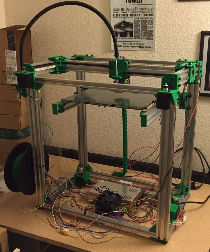 Cheaper options are essentially printed circuit boards with preheated wiring. To operate on this type of table, you will need to put borosilicate glass, which will scratch and crack during operation. Therefore, the best solution is an aluminum table.
 - Stepper motors. Most models, including the i2 and i3, use NEMA 17 size motors, two for the Z axis and one each for the X and Y axes. Finished extruders usually come with their own stepper motor. It is better to take powerful motors with a current in the motor winding of 1A or more, so that there is enough power to lift the extruder and print without skipping steps at high speed.
- Basic set of plastic fasteners.
- Belt and gears to drive it.
Examples of elements appearance: 1) MK8 extruder; 2) Arduino processor board; 3) RAMPS control board; 4) motor controllers; 5) aluminum heated table; 6) NEMA 17 stepper motor; 7) a set of plastic fasteners; 8) drive gears; 9) drive belt
This is a list of items to be purchased.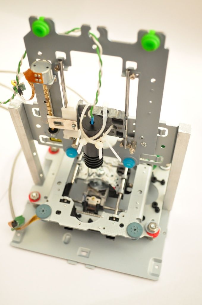 Hardcore users can assemble some of them themselves, but for beginners, I strongly recommend purchasing ready-made solutions.
Yes, you will also need various small things (studs, bearings, nuts, bolts, washers ...) to assemble the case. In practice, it turned out that using a standard m8 stud leads to low printing accuracy on the Z axis. I would recommend immediately replacing it with a trapezoid of the same size.
M8 trapezoid stud for Z axis, which will save you a lot of time and nerves. Available for order on all major online platforms
You also need to purchase customized plastic parts for the X axis, such as these from the MendelMax retrofit kit.
Most parts available at your local hardware store. On RepRap you can find a complete list of necessary little things with all sizes and patterns. The kit you need will depend on the choice of platform (we'll talk about platforms later).
What's the price
Before delving into some aspects of the assembly, let's figure out how much such entertainment will cost for your wallet.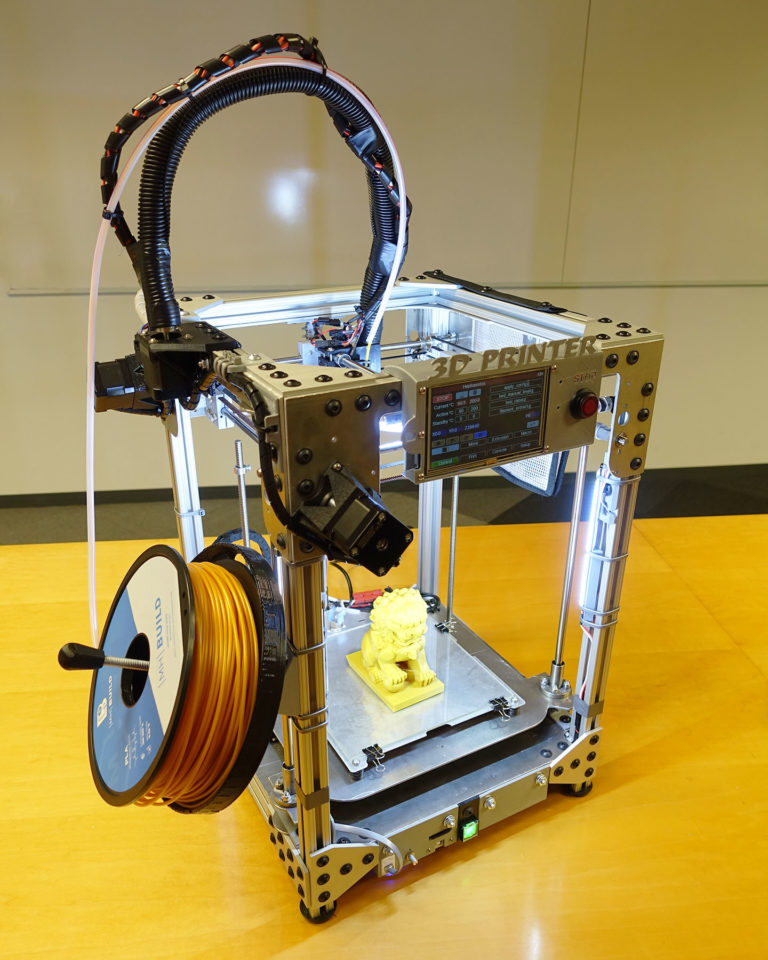 Below is a list of parts required for purchase with an average price.
Platform selection
The community has already developed a number of different platforms for assembling printers - the most optimal case designs and the location of the main elements, so you do not have to reinvent the wheel.
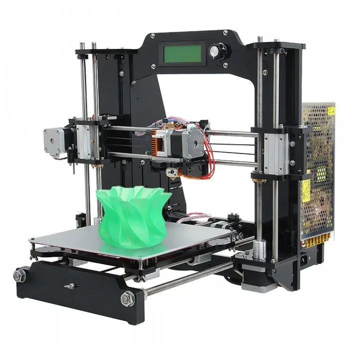
i2 and i3 are key platforms for self-assembly printer enclosures. There are also many modifications of them with various improvements, but for beginners, these two classic platforms should be considered, since they do not require special skills and fine-tuning.
Actually, illustration of platforms: 1) i2 platform; 2) i3 platform
On the plus side of i2: it has a more reliable and stable design, although it is a little more difficult to assemble; more opportunities for further customization.
The i3 variant requires more special plastic parts to be purchased separately and has a slow print speed. However, it is easier to assemble and maintain, and has a more aesthetically pleasing appearance.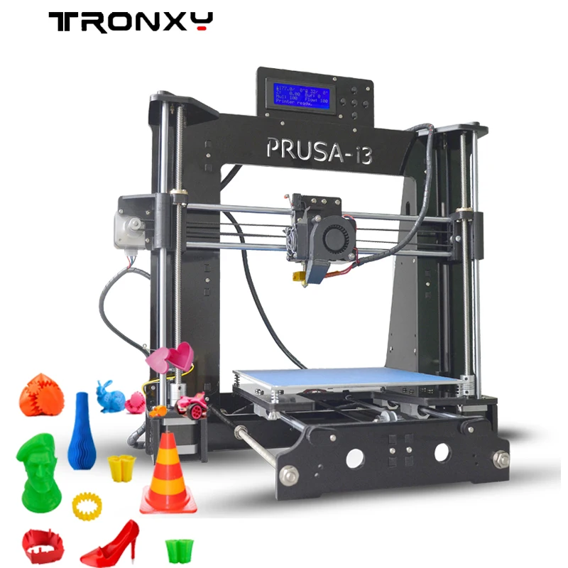 You will have to pay for simplicity with the quality of printed parts - the body has less stability than i2, which can affect print accuracy.
Personally, I started my experiments in assembling printers from the i2 platform. She will be discussed further.
Assembly steps, challenges and improvements
In this block, I will only touch on the key assembly steps using the i2 platform as an example. Full step by step instructions can be found here.
The general scheme of all the main components looks something like this. There is nothing particularly complicated here:
I also recommend adding a display to your design. Yes, you can easily do without this element when performing operations on a PC, but it will be much more convenient to work with the printer this way.
Understanding how all components will be connected, let's move on to the mechanical part, where we have two main elements - a frame and a coordinate machine.
Assembling the frame
Detailed frame assembly instructions are available on RepRap.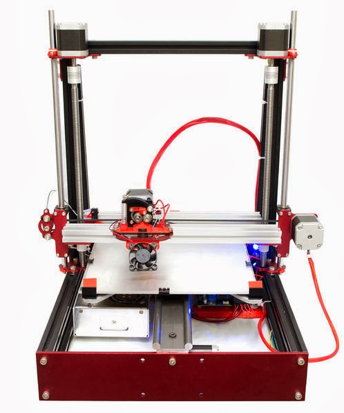 Of the important nuances - you will need a set of plastic parts (I already talked about this above, but I'd better repeat it), which you can either purchase separately or ask your comrades who already have a 3D printer to print.
The frame of the i2 is quite stable thanks to its trapezoid shape.
This is how the frame looks like with parts already partially installed. For greater rigidity, I reinforced the structure with plywood sheets
Coordinate machine
An extruder is attached to this part. The stepper motors shown in the diagram above are responsible for its movement. After installation, calibration is required along all major axes.
Important - you will need to purchase (or make your own) a carriage for moving the extruder and a mount for the drive belt. Drive belt I recommend GT2.
The carriage printed by the printer from the previous picture after it has been assembled.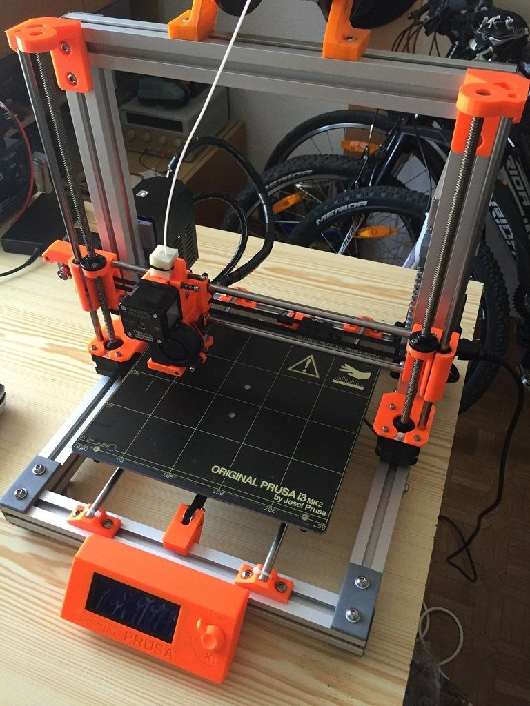 The part already has LM8UU bearings for guides and belt mount (top)
Calibration and adjustment
So, we completed the assembly process (as I said, it took me 150 hours) - the frame was assembled, the machine was installed. Now another important step is the calibration of this very machine and extruder. Here, too, there are small subtleties.
Setting up the machine
I recommend calibrating the machine with an electronic caliper. Do not be stingy with its purchase - you will save a lot of time and nerves in the process.
The screenshot below shows the correct constants for the Marlin firmware, which must be selected in order to set the correct number of steps per unit of measure. We calculate the coefficient, multiply it, substitute it into the firmware, and then upload it to the board.
Marlin 9 firmware constants0022
For high-quality calibration, I recommend relying on larger numbers in measurements - take not 1-1. 5 cm, but about 10. So the error will be more noticeable, and it will become easier to correct it.
Calibrating the extruder
When the frame is assembled, the machine is calibrated, we start setting up the extruder. Here, too, everything is not so simple. The main task of this operation is to correctly adjust the supply of plastic.
If underfeeding, the printed test item will have noticeable gaps, like test die 1. Conversely, the result will look bloated if plastic is overfed (dice 2)
Getting Started Printing
It remains for us to run some CAD or download ready-made .stl, which describe the structure of the printed material. Next, this structure needs to be converted into a set of commands understandable to our printer. For this I use the Slicer program. It also needs to be set up correctly - specify the temperature, the size of the extruder nozzle. After that, the data can be sent to the printer.
Slicer interface
As a raw material for printing, I recommend starting with regular ABS plastic - it is quite strong, products made from it are durable, and it does not require high temperatures to work with. For comfortable printing with ABS plastic, the table must be heated to a temperature of 110-130 ° C, and the extruder nozzle - within 230-260 ° C.
Some important details. Before printing, calibrate the machine along the Z axis. The extruder nozzle should be approximately half a millimeter from the table and ride along it without distortion. For this calibration, a regular sheet of A4 paper inserted between the nozzle and the surface of the heated table is best suited. If the sheet can be moved with little effort, the calibration is correct.
Another thing to keep in mind is the surface treatment of the heated table. Usually, before printing, the surface of the table is covered with something that hot plastic sticks to well. For ABS plastic, this can be, for example, Kapton tape. The disadvantage of adhesive tape is the need to re-glue it after several printing cycles. In addition, you will have to literally tear off the adhering part from it. All this, believe me, takes a lot of time.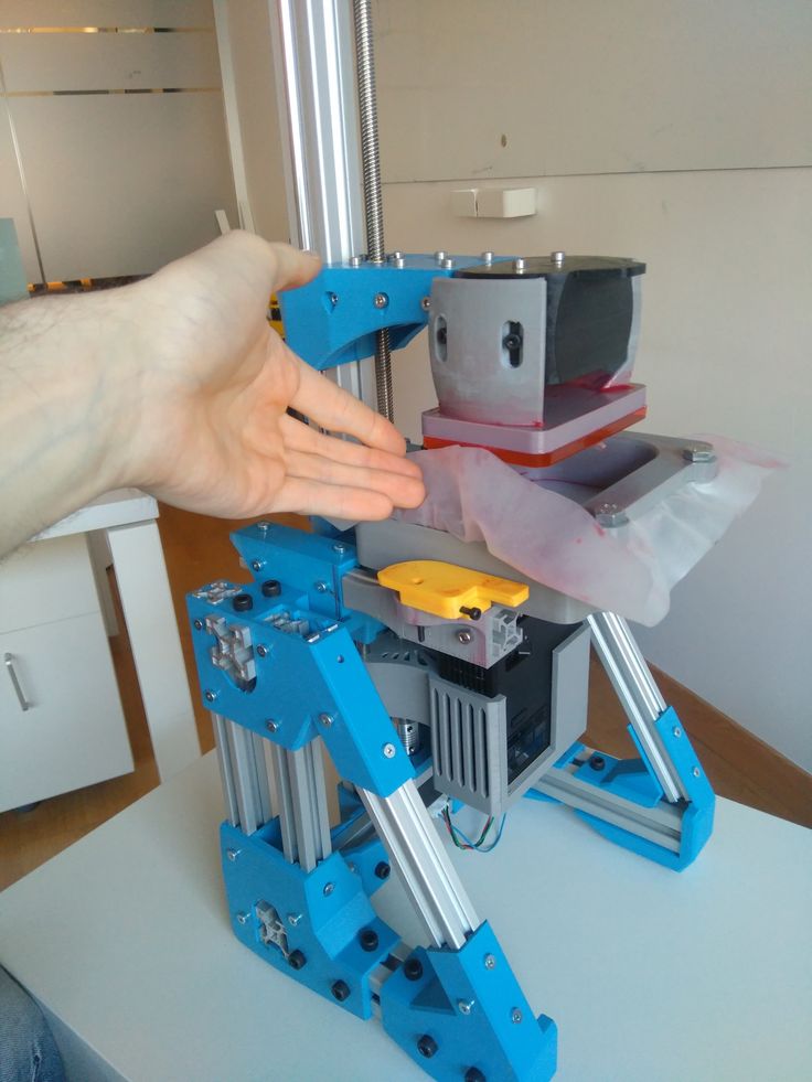 Therefore, if it is possible to avoid this fuss, it is better to avoid it.
An alternative option that I use instead of scotch tape is to apply several layers of ordinary light beer, followed by heating the table to 80-100 ° C until the surface is completely dry and re-applying 7-12 layers. It is necessary to apply the liquid with a cloth moistened with a drink. Among the advantages of this solution: ABS plastic separates from the table on its own when it cools down to about 50 ° C and is removed without effort, the table does not have to be peeled off, and one bottle of beer will last you for several months (if you use the drink only for technical purposes :)).
After we have collected and configured everything, we can start printing. If you have an LCD screen, then the file can be transferred for printing using a regular SD card.
The first results may have bumps and other artifacts - do not worry, this is a normal process of "grinding" the printer elements, which will end after a few print cycles.
Tips to make life easier (and sometimes save money)
In addition to the small recommendations given in the text above, in this section I will also give a short list of tips that will greatly simplify the operation of a 3D printer and the life of its owner.
- Do not experiment with nozzles. If you plan to immediately print from materials that require high temperatures, then it is better to immediately take the MK10 extruder. On MK8, you can "hang" special nozzles that support high-temperature conditions. But such modifications often cause difficulties and require special experience. It is better to avoid this fuss on the shore by simply installing the right extruder for you.
- Add starter relay for heated table. Improving the power supply system for this important printing part with a starter relay will help solve the known problem of RAMP 1.4 - overheating of the transistors that control the power of the table, which can lead to failure of the board.
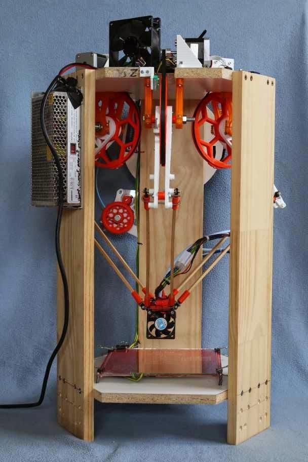 I made this upgrade after having to throw away a few RAMPS 1.4s.
 - Select the correct filament diameter for printing. I recommend using 1.75mm plastic for MK8 and MK10. If we take plastic, for example, 3 mm, then the extruder simply does not have enough strength to push it at an acceptable speed - everything will be printed much longer, and the quality will drop. ABS plastic is ideal for MK8, MK10 will be able to produce products from polycarbonate.
- Use only new and precise X and Y guides. Print quality will be affected. It is difficult to count on good quality with bent or deformed guides along the axes.
- Take care of cooling. During my experiments with various extruders, the MK10 showed the best results - it prints quite accurately and quickly. The MK10 can also print plastics that require a higher print temperature than ABS, such as polycarbonate. Although it is not as prone to overheating as its younger brother MK8, I still recommend taking care of its cooling by adding a cooler to your design.
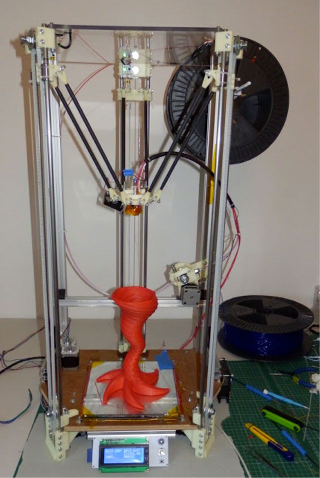 It must be permanently enabled, this option can be configured in Slicer. You can also add coolers to keep the stepper motors at an acceptable temperature, however, make sure that their air flows do not fall on the printed part, as this can lead to its deformation due to too rapid cooling.
 - Consider heat retention. Yes, on the one hand, we are struggling with overheating of the elements. On the other hand, a uniform temperature around the printer will contribute to high-quality printing (the plastic will be more pliable). To achieve a uniform temperature, you can put our printer, for example, in a cardboard box. The main thing is to connect and configure the coolers before that, as described above.
- Consider insulating your desk. Heated table heats up to high temperatures. And if part of this heat leaves properly, heating the printed part, then the second part (from below) just goes down. To concentrate the heat from the table onto the part, you can perform an operation to insulate it.
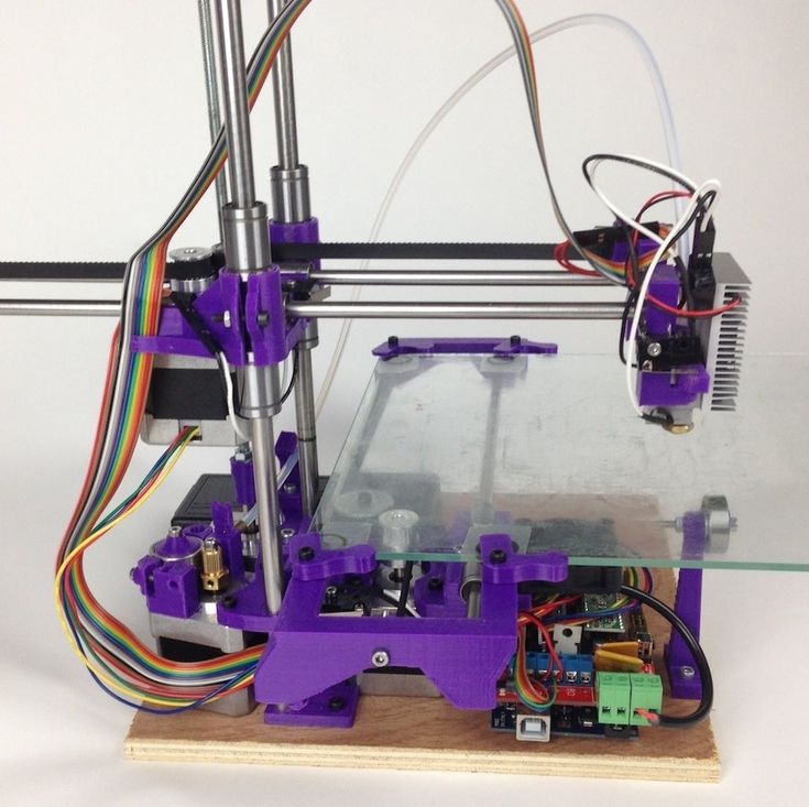 To do this, I simply attach a cork mouse pad to its bottom using stationery clips.
Pins
I am sure that during the assembly process you will encounter a number of difficulties specific to your project. Neither this text nor even the most detailed guides will insure against this.
As I wrote in the introductory part, the above does not claim the status of a detailed assembly manual. It is almost impossible to describe all the stages and their subtleties within the framework of one such text. First of all, this is an overview material that will help you prepare for the assembly process (both mentally and financially), understand whether you personally need to bother with self-assembly - or give up on everything and buy a ready-made solution.
For me, assembling printers has become an exciting hobby that helps me solve some issues in home and work affairs, take my mind off programming and do something interesting with my own hands. For my children - entertainment and the opportunity to get unusual and unique toys.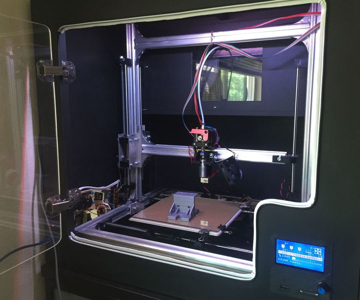 By the way, if you have children whose age allows them to mess around with such things, such an activity can be a good help for entering the world of mechanics and technology.
For everyone, the vectors of using 3D printers will be very different and very individual. But, if you decide to devote your personal time to such a hobby, believe me, you will definitely find something to print :)
I will be glad to answer comments, remarks and questions.
What to read/see
- what can be printed;
- 3D printer forum;
- RepRap community site with model descriptions and assembly instructions;
- printer that prints electronics.
Subscribe to the Telegram channel "DOU #tech" so you don't miss new technical articles.
Topics: DIY, embedded, tech
Homemade 3D printer on Black Pill (STM32F401CCU6)
Good afternoon.
I would like to tell you my thorny path in building a homemade 3D printer.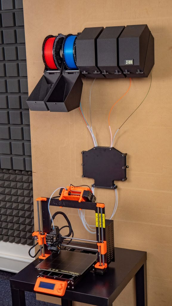
For a long time I dreamed of a 3D printer, but I could not decide whether to buy ready-made or build it myself.
It all started with an analysis of the models offered on Aliexpress. I understood that due to the increase in prices, it does not make sense to buy a ready-made version, since I will not use the printer often. After watching a "bunch" of videos about homemade 3D printers, I decided what kind of printer functionality I need. Most of the DIY was done with an Arduino Mega 2560 expansion board called RAMPS. There is nothing wrong with this solution as it is quick and easy. But I never liked the concept of a “sandwich”, and in consequence of the rise in price of the Arduino Mega, I decided to find another electronic basis for my homemade 3D printer. After reviewing a lot of offers, I realized that buying a board designed for 8 bits in 2021 is no longer relevant, and ready-made solutions for 16 and 32 bits are unreasonably expensive and most of the presented models have many functions that I will not use.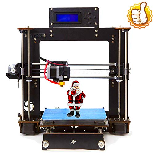 Suddenly, I "stumble" on an article by a respected 3dmaniack with his solution and a board called RABPS. I'm redoing a project on short notice, but I'm running into an unforeseen problem. The RABPS board is based on the Blue Pill (STM32F103C8T6) microcontroller, but there are two versions of the microcontroller with 64kb and 128kb Flash memory. Naturally, our "friends from the Middle Kingdom", replacing labels, sell a cheaper option under the guise of an expensive one. As a result, firmware weighing more than 120 kb did not fit on the board. This failure did not stop me, but on the contrary, gave me an incentive to look for solutions. And continuing the search, I found a mini project by zooinginer, based on the same RABPS board, but based on the Black Pill microcontroller (STM32F401CCU6). With minimal modifications in the form of a pair of jumpers and cut tracks, this microcontroller will function in this board. The big difference between STM32F401CCU6 and STM32F103C8T6 is that under this marking there is always a 256 KB Flash memory, which is enough for flashing.
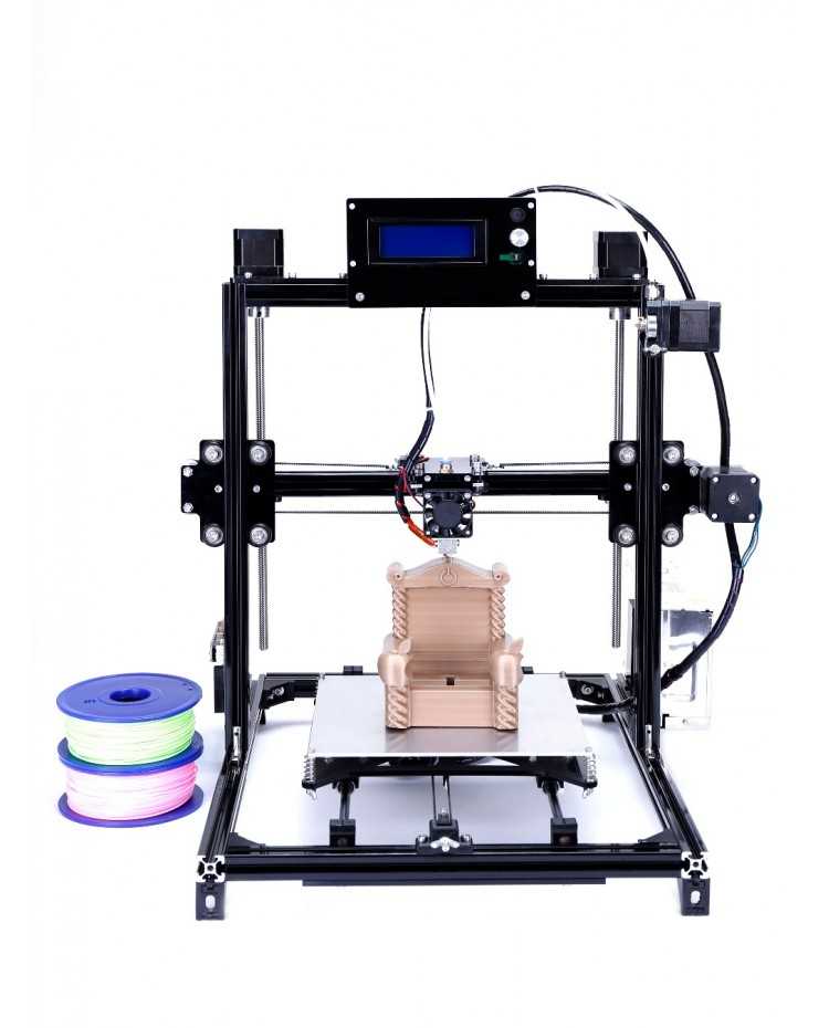 Well, that's all, I found the answer to all my requests and it remains only to design a printed circuit board and manufacture it.
Next, I will divide my path into 3 parts.
1) PCB manufacturing;
2) Firmware;
3) Hull and kinematics.
I would like to start my story about the thorny path of a homemade 3D printer.
So, in this part of the article, I will consider everything related to the board, from design to the finished solution.
As mentioned in the introduction, I took as a basis the project of the respected 3dmaniack with his solution and board called RABPS and the zooinginer's project with the adaptation of the RABPS board to Black Pill (STM32F401CCU6). Having experience in the Sprint Layout program, a PCB design was created in a couple of evenings, but, as it happens, there were some mistakes. From a banal error in the size of the board components, which is quickly corrected, up to errors in the LUT technology. Looking ahead, I left him in the direction of the photoresist.
Let's get started.
We print photomasks, which will illuminate the photoresist. I printed on a laser printer and the toner density on the template was medium, which subsequently led to a poor result.
Violet streaks and dots are visible on the unexposed areas. This indicates that in these places the photoresist began to light up through the gaps in the template. This led to the fact that in the process of washing off the excess photoresist, the necessary tracks began to be washed off. The solution to this problem is simple: you should make graphite dust by rubbing the pencil tip on sandpaper, and gradually rub it into the template. As a result, the template becomes more contrast and the problem is eliminated. Having corrected the defect in the template and obtained an excellent result, we wash off the unnecessary photoresist in a 3% solution of soda ash, and proceed to the etching process. I poison in a solution of peroxide and citric acid. The process is not fast. Although when the solution is heated, it goes faster. After etching, we remove the remnants of the photoresist from the tracks by soaking the board in the same 3% soda ash solution overnight, and enjoy the good result.
Next comes the optional part, namely the solder mask coating of the board. There are many types of masks, I settled on a Dynamask 5000 film solder mask, bought at the Chip and Dip store. The application process is very simple. Gradually peeling off the protective film, we rub the mask to the board. Next, according to the template, we illuminate the mask, and after that, wash off the unexposed places in a 3% solution of soda ash, and send it to be tanned in the oven for one hour at a temperature of 100 degrees Celsius. We receive.
Then we move on to soldering the components.
Since I don't have a device (mini-machine) for drilling boards, I use a conventional screwdriver. But because of its mass, at the slightest inclination, the drill often breaks. I tried to translate most of the components into smd execution, for example, voltage stabilizers, resistors and capacitors. All denominations are indicated in the scheme. The result is such beauty.
This is the second part of the story about a homemade 3D printer.
It's about the firmware, or rather about the problems that I encountered.
For me, this stage was the longest. First, I dealt with the Visual Studio Core program and its platformio ide add-on. Then there were “dancing with a tambourine”, due to the selection of the platformio ide version, since the firmware refused to assemble with some versions. I first put Visual Studio Core not on drive C, but on an additional one, because of this, the firmware also did not compile. It also took a lot of time that when you open the firmware you don’t need to immediately press build (first you need to wait 10-20 minutes for all libraries to be downloaded from the Internet). Dear zooinginer in his article described what needs to be done so that the firmware is compiled and installed on Black Pill. With a lot of torment, with the help of diman77, I still managed to compile and assemble the firmware, and then, using the Marlin setup video, I set the parameters for my configuration and for my self-made Smart_Controller.
Under the article I will leave all the necessary links. If you are interested in my homemade Smart_Controller, I can post a separate article on it.
This is the third part of the story about a homemade 3D printer.
It's about choosing kinematics and bringing drawings to life.
There are many types of kinematics on the Internet, but for myself I singled out three: Prusa (“drygostok”), H-Bot and Ultimaker. I will briefly describe the pros and cons of these kinematics (in my opinion).
Prusa (“drygostol”)
Pros: ease of assembly, cost of components, easy access to the part.
Cons: open working chamber.
H-Bot
Pros: Printing accuracy, closed working chamber.
Cons: stretching of the belt due to its large length.