3D printing thread inserts
Ultimate Guide to Threaded Inserts and 3D Prints
Download the full Guide
as a PDF!
The simple post-processing techniques presented in this guide are an excellent way for professionals to create low-cost silicone molds, threaded inserts for enclosures, vacuum formed parts, and more.
Threaded brass inserts can be a great way to add longevity to 3D printed enclosures that need to accept screws.
In this “how to” we will show you some of the best practices associated with installing threaded brass inserts into your 3D printed enclosures.
Working time will vary depending on your model and how many inserts you plan to install. The process shown took us about 10 minutes from start to finish.
SUPPLIES
Soldering Iron
Threaded brass inserts with matching machine screws
Washers
Pliers
Vise
Heat resistant gloves
Eye protection
Respiratory mask
Need some of these products? We've curated an Amazon wish list for you.
STEP 1: OBTAIN YOUR MODEL
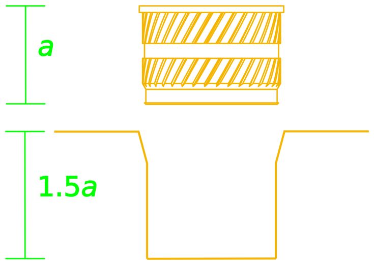
If you are designing your model to meet a specific need, remember to design the holes in your model slightly smaller than the inserts you plan to install. This will account for any plastic that melts when installing inserts. If you are adding inserts to a downloaded model, purchase your inserts with the hole diameter in mind.
For our model, we chose this “Light Switch Box” designed by Thingiverse user qbasan.
Manufacturers of threaded brass inserts specify the hole size needed for the insert.
Step 2: Prepare & Print
When installing inserts, changing a few print settings in MakerBot Print can be a big help.
Increase the number of shells in your print. This will leave more plastic around inserts.
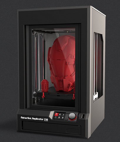
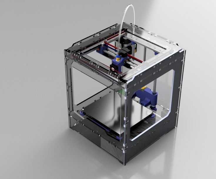
Once you have selected your settings you can print your object. We chose to print our model on the MakerBot Replicator+.
STEP 3: ROUGHING
Supplies Used: Needlenose pliers
Once your model has been printed and removed from the build plate, remove any rafts or support material.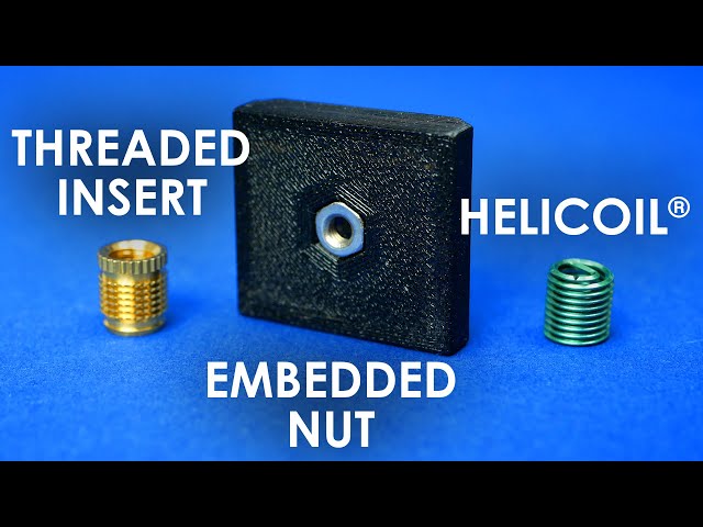
Supplies Used: Soldering Iron
Allow your soldering iron to heat for 3-5 minutes before installing inserts. This will ensure that you have to use the least amount of force to install inserts.
The 2021 Guide to 3D Printing Materials
Learn about polymers, composites, and metals all available for 3D Printing!
Supplies Used: Soldering Iron
Before installing your inserts, it’s also important that your model be secure. If your model moves during installation of an insert, you could damage the void or even the model itself.
We used a multi-axis vice that allowed us to work on the model from a few different angles.
Secure the model
Adjust the angle of the model
Supplies Used: (continued use through Step 9) Multi-axis vice, soldering iron, threaded brass inserts, and pliers
Because PLA has a relatively low heat deflection temperature and can deform at moderate temperatures, it is important to install inserts gradually.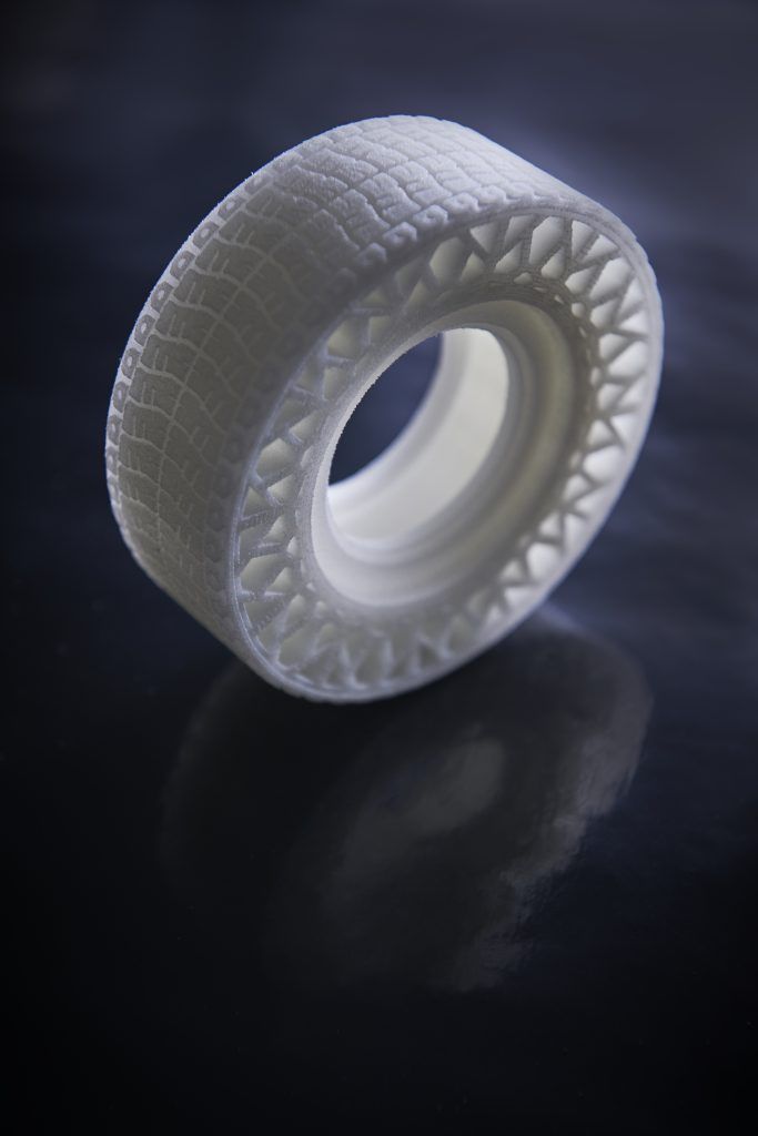
A: Grasp your insert with pliers
B: Position insert over hole
C: Press the insert half way into your print holding the soldering iron vertically
D: Move on to the next insert
Push lightly, your soldering iron should do most of the work for you
As brass transfers temperature relatively quickly, your inserts should be cool within a minute or so.
STEP 8: COMPLETELY INSTALL INSERTS
Once you’ve allowed your model to cool for a minute or so, install the inserts until they are flush with the top of your model.
When completing the installation of inserts be sure to avoid:
Installing too quickly
Pushing down on your inserts with too much force
Caution:
Never attempt to hold inserts in place with your hand when installing. Always use pliers.
Supplies Used:
Screws & washers
Screwdriver
Multi-axis vice
Thread in your screws using a screwdriver or drill.
Insert washers and screws
Insert additional hardware
Caution: Be sure not to over tighten. This can force the insert free from the surrounding plastic.
If you over tighten your screws, you may need to melt out your inserts and reinstall.
Here is our final part. After installing inserts, screws, and washers, we added the final switches to this electrical enclosure.
Visit one of our other applications pages for tips on how to take your print even further.
We recommend that you visit our pages on:
Vacuum Forming
Silicone Molding
Painting
Last but not least, remember to share your work with us on Thingiverse and social media @MakerBot.
We can’t wait to see what you make!
Light Switch Box
Qbasan
11/12/2014
https://www.thingiverse/thing:541876
Powered by MakerBot Learning.
3D Printing Threads and Adding Threaded Inserts to 3D Printed Parts (With Video)
There are many ways to attach screws to 3D printed parts, including inserts, tapping, and even 3D printed screw threads.
Screws are among the most popular fasteners in any material. Can you use off-the-shelf screws with your 3D printed parts? The answer is a clear yes, for both stereolithography (SLA) and selective laser sintering (SLS) parts.
In this article, we explore different methods of using metal screws with 3D printed parts, and provide some tips for incorporating screw threads directly into your 3D design.
Watch our application video about 3D printing threads and threaded inserts for 3D printed plastics.
Video Guide
Having trouble finding the best 3D printing technology for your needs? In this video guide, we compare FDM, SLA, and SLS technologies across popular buying considerations.
Watch the Videos
Let’s take a look at the various design options for 3D printed threads, which we’ve collected over the years within Formlabs and based on feedback from our customers. Our test part is designed to showcase all these methods at once:
We’ve grouped these options based on the type of fastening, with pros and cons of each option listed for different use cases.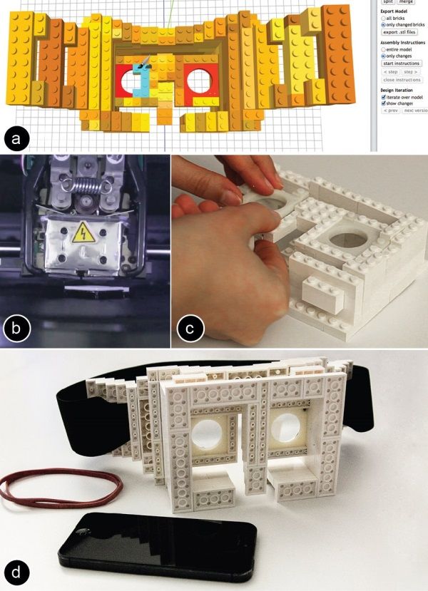
Sample part
See and feel Formlabs quality firsthand. We’ll ship a free sample part printed on an SLA or SLS 3D printer to your office.
Request a Free Sample Part
In this section, we look at three ways to incorporate inserts and nuts into your completed 3D prints for strong, long-lasting fastening that stands up to multiple cycles of assembly and disassembly.
Pros
-
Very good hold into 3D printed parts
-
Metal threads are strong and wear-resistant
-
Installs with a simple press fit
Screw-to-expand inserts are cylindrical, with a slight taper and knurling on the exterior surfaces. During the design stage, incorporate a boss with a depth and diameter based on the insert’s specs into your part. Print and post-process the part as normal, following the usual steps for SLA or SLS post-processing, taking care to make sure no extra material remains inside the cavity, and install the insert with a simple press fit.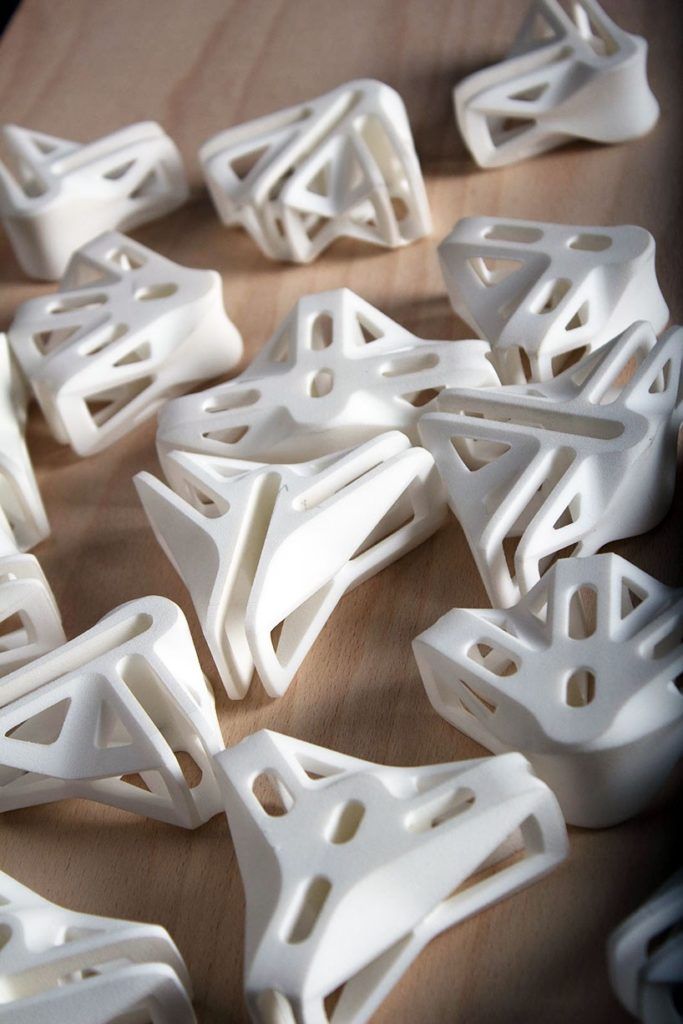 Adding a screw will press the knurled surface into the surrounding printed material, creating a strong friction fit.
Tip for using screw-to-expand inserts with 3D printed parts made with SLA 3D printing: Wash the part as normal, insert the screw-to-expand insert, install a screw, and post-cure the part with the screw in place. Saving this step for last reduces the chance that the insert will crack the surrounding material when expanded.
Heat-set threaded inserts are designed to be installed into thermoplastics using a soldering iron with an installation tip. They can also be used as glue-in inserts in thermoset materials, such as SLA parts.
To install in a thermoplastic part, like one printed with SLS Powders, follow the installation instructions for your particular hardware. The typical process is to use a soldering iron, with or without a special attachment, to heat the insert, which conducts heat into the surrounding plastic. The surrounding material softens and, by pressing down with the soldering iron, you can gently press the insert into the printed part.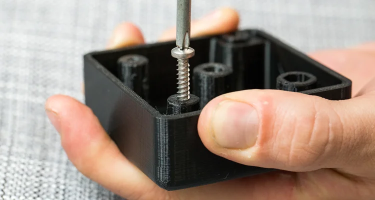 Be sure to allow enough time for the material to cool down and regain strength before installing a screw.
To install in a thermoset part, like one printed with SLA Resins, glue can be used to hold a heat-set insert in place. Unlike with traditional installation, make sure to design your boss to match the widest diameter of the insert, and use a bead of cyanoacrylate (CA) glue or epoxy to hold it in place when installed. Be sure to allow enough time for your glue to fully cure before installing a screw.
Note: In the SLS 3D printed part photographed for this article, the boss is sized for a press-fit, as we recommend here for thermoset plastics. This also works, with a drop of glue or epoxy, for thermoplastic parts, but won’t have as strong a hold as a true heat-set installation.
Although an additional step of soldering or gluing is required, heat-set threaded inserts for both SLS and SLA parts offer improved security and strength compared to screw-to-expand inserts With either method, these are a great option to gain a little extra security and strength compared to screw-to-expand inserts, although the additional step and equipment may be inconvenient.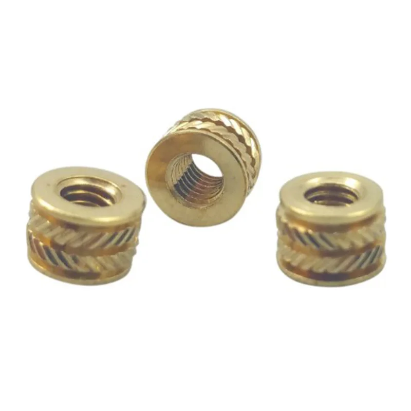
Cons
-
Pocket or boss needs to be designed into the part, and accessible after printing
-
Depending on geometry, may require glue and curing time
Designing a pocket or boss that securely holds a nut into the part itself is another method to get metal-on-metal contact. Hexagonal or square nuts can be used, and even locking nuts are possible to accommodate. There are many design variations for this method—just make sure your pocket or boss is easily accessible (i.e. not on an interior surface) so that the nut can be installed. For extra security, a drop of cyanoacrylate (CA) glue will hold the nut in place.
White Paper
Stereolithography (SLA) 3D printers such as the Formlabs Form 3+ have high accuracy and precision, and offer a wide range of engineering materials. Download our white paper for specific recommended design tolerances.
Download the White Paper
For speed and simplicity, it might be preferable to forego inserts and nuts in favor of screwing directly into a 3D printed part.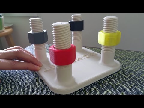 Whether tapping threads or using a self-tapping screw, off-the-shelf hardware designed for use with plastics work well with 3D printed materials like resins and thermoplastic powders.
Using a thread tap designed for plastic is a quick, economical way to add screw threads to 3D printed parts. It doesn’t require any extra design steps, and most shops that work with plastics will already have the equipment required.
Self-tapping screws, also called thread-forming screws, can be inserted into a negative feature with no preparation work done to the part. Follow the manufacturer’s guidelines for boss dimensions.
It’s suggested to use these with materials that are ductile, or have high elongation. Formlabs Nylon 11 Powder or Nylon 12 Powder are both suitable for this, as are the Tough and Durable Resins in the Formlabs SLA material family. Brittle materials, or those with low elongation (such as the Rigid Resins in the Formlabs SLA material family), may crack when used with self-tapping screws, so take caution and wear eye protection when using these materials.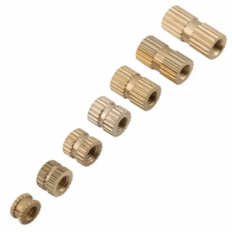
Including threaded geometries in your printed part can be effective if you follow certain guidelines. Stick to larger thread sizes, at least ¼”–20 (imperial) or M6 (metric) or larger; reduce stress concentrations with fillets; and use thread profiles that are designed for plastics. For smaller screws, the threads should be customized to create a better fastener. For example, printing a semi-circular thread profile (on screw and nut) and using a 0.1 mm offset gives better thread engagement with improved wear characteristics.
SLA and SLS 3D printing are generally preferable for this method over FDM, because they are more precise and can create parts with a smoother surface finish. Any material with particularly low surface friction, such as Durable Resin, is less likely to show wear over multiple cycles of assembly and disassembly.
When preparing your part for printing, it's important to minimize support structures on any threaded surfaces to ensure your parts will come together smoothly without additional post-processing.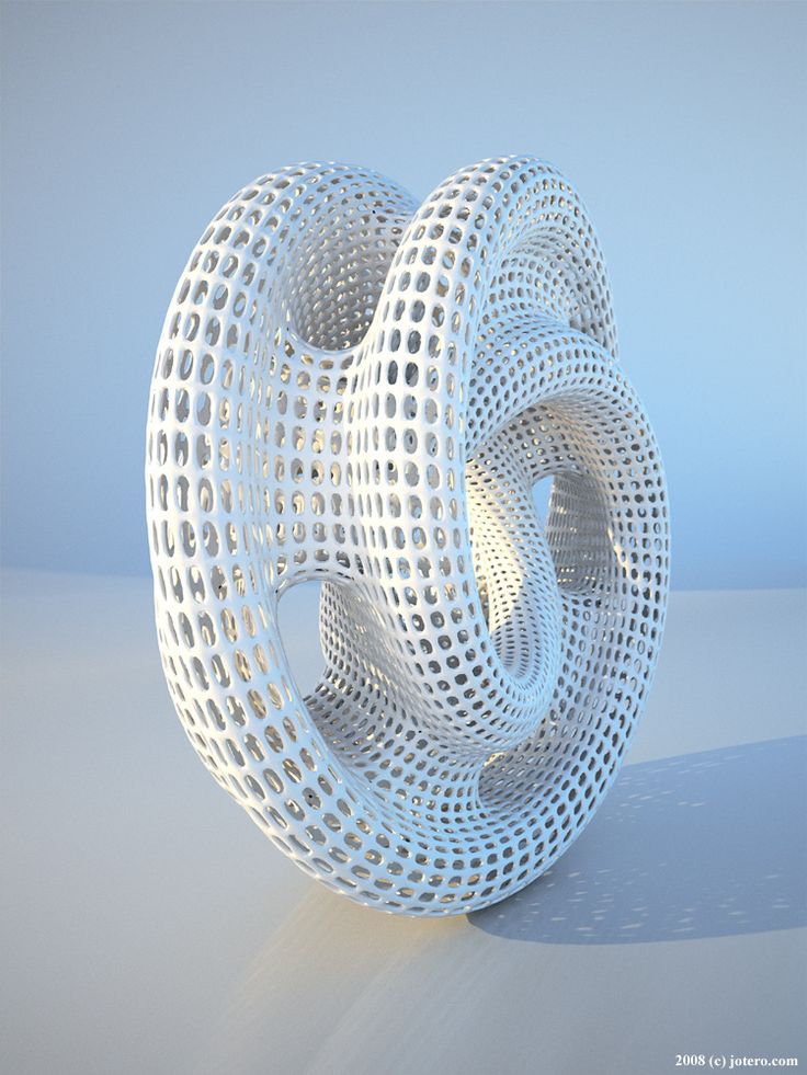
There are many options for combining multiple 3D printed components using screws and threaded fasteners. From directly 3D printing threads to using off the shelf inserts, you can choose any of the methods outlined above, based on the chosen material, the number of cycles of assembly and disassembly you anticipate, the strength required, and the amount of extra steps your workflow can accommodate.
Curious to see what 3D printing material might be right for your application? Use our interactive wizard to choose the best 3D printing material or request a free 3D printed sample part to see the quality firsthand.
Explore 3D Printing MaterialsRequest a Free Sample Part
3D printed mesh fabric
Prologue
Hello everyone! I am developing "smart sequins" - electromechanical color-reproducing devices for designer clothes. Our team is passionate about the idea of creating clothes and accessories that can change their color at the request of the owner or depending on environmental conditions.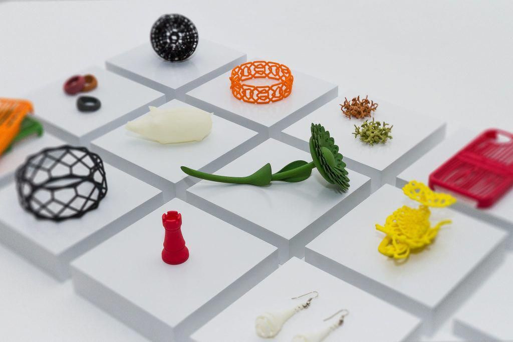
In this article I want to talk about how we used 3D printing in our project, share our experience and tools.
3D printing on fabric
One of the tasks that I had to solve was to figure out how to make an elastic fabric out of plastic sequins, which in its properties would resemble textile materials. At the same time, it is necessary to provide for the possibility of easily creating electrical connections between the sequins.
There are quite a few articles and materials on making clothes on a 3D printer. Many different methods have already been invented, from creating hinges right in the printing process to printing with elastic plastics.
While looking for a solution, I came across this video. From it, I first learned about the method of printing on mesh fabric using a conventional FDM 3D printer.
The author himself claims that he spied the idea here: Shorey Designs.
The essence of the method is very simple. We create a 3D model of a fragment of the future canvas, then arrange a lot of fragments so that we get a whole canvas.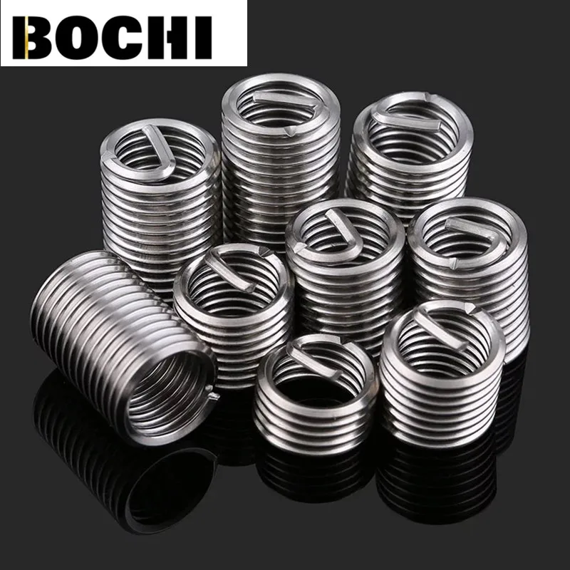 We start the slicer and prepare the G-code. Before sending it to the printer, you need to insert a pause and raise the extruder before printing a certain layer. The printer will stop during operation. At this point, we cover the printed layers with a mesh cloth. We continue to print. Due to the presence of large holes in the fabric, the layers of plastic will interlock with each other, as in conventional printing, and the mesh fabric will be firmly integrated into the parts.
Modifying G-code
I use Cura version 3.2.1 as a slicer. 3D printer - homemade H-bot controlled by a board based on ATmega2560 (RAMPS 1.4) with Marlin firmware.
To pause the printer, there is an M25 command. Command for lifting in Z by 20mm: G0 Z20. It is noteworthy that the M25 must go before the ascent, otherwise the next command is processed first. Why this happens is a mystery to me, apparently somehow connected with the processing of commands by the printer.
Add commands to G-code:
Operation automation
Manually searching for the required line in the G-code file and inserting commands is not the most modern solution, I thought and wrote a simple program that allows you to open and view toolpaths.
For the convenience of viewing the layers, the “explode” command is provided, which allows you to visually increase the distance between the layers of the model. After pressing the "insert pause" button, the distance between the marked layer (red) and the previous one increases. This means that the print will be interrupted precisely between these layers.
To understand where one layer ends and the next begins, I used the comments that Cura kindly provides in its output files. The keyword ";LAYER:X" allows you to accurately find the boundaries of layers in a text file.
Pressing the "write file" button allows you to save the modified G-code in the specified location.
Save the file to the SD card and bring it to the printer.
It's funny that only while preparing this article, I came across a video that tells how you can do the same using standard Cura tools ... But the process is already running, it's too late to slow down! Here, starting at 7:30, it is described in detail how to do it.
Well ... hurry up - learn how to parse G-code!
Trying to print
Formation of the first layers. We print on glass. Heated table. Table temperature 60⁰С, printing temperature 220⁰С. The print material is PLA plastic. Layer height 0.2mm.
During the pause, place a piece of fabric and fix with magnets. Since the table is aluminum (paramagnetic), we put the magnets on the top and bottom sides of the table. Fixation is made in 4 places, in the corners of the part. This is quite enough. The main thing is not to place them too close to the print area, otherwise the magnets will stick to the print head.
After 40 minutes, this is the structure. The thickness of each 6 carbon element is 1mm. The gap between the elements is 2mm.
In this experiment, tulle was used as the backing fabric. It is a lightweight mesh fabric of medium stiffness, woven from polyester threads.
Experiments have also been made with mosquito net printing.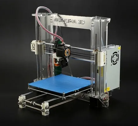 In the hardware store, there were two types of them: fabric and fiberglass. Fabric mesh is softer than tulle, but has greater mechanical tensile strength, as well as less elasticity. The fiberglass mesh is harder than tulle, its mechanical strength is the highest of all participants in the experiment.
Hexagonal sequin printing on fiberglass mosquito net. The gap between the elements is 1mm. The matrix is very hard. Clearance is clearly not enough.
Round sequin printing on fiberglass mosquito net. The gap between the circles is 2mm. It has a lot of flexibility, but there is too much unfilled space between the sequins.
After several test prints, the fabric mesh was chosen. She formed the basis of the matrix of smart sequins. The resulting matrix can bend in all directions.
The video demonstrates the operation of the program, the printing process and the final result.
Conclusion
The method of printing on mesh fabric proved to be very good. This is an ideal solution for our task, because the fabric substrate allows us to weave conductive threads into it, which are used to provide electrical connection between the individual sequins of the matrix. Moreover, the formation of a “pattern” of conductors can be carried out at the preparatory stage. And the 3D printing itself is later.
The strength of the resulting structure depends mainly on the strength of the substrate material. But the flexibility will also depend on the distance between the sequins, as well as their shape.
The developed program still needs to be improved. For example, you can finish the retract before lifting, allow the user to adjust the height of the extruder.
Link to the source code for the processing environment.
And also a link to the release with the .exe file of the program.
By the way, we recently launched our "smart sequins" on the crowdfunding platform. For those who want to get to know our work better, I will leave a link.
3D printing and conductive threads create clothes with buttons
Engineers from the Netherlands and Canada have developed a method to create two-layer clothing with buttons integrated into the fabric. They suggested embroidering an electrical circuit with conductive threads and using a 3D printer to print plastic buttons on fabric with thin metal plates that complete the circuit. An article on the method was presented at the DIS 2020 conference.
There are quite a few attempts to create smart clothes: mostly research projects, although there are already commercial examples, such as a jacket from Google and Levi's. As a rule, they have the same, still unsolved, problem: it is difficult to make clothes with electronic components as flexible, stretchable and, as a result, comfortable to wear as regular jackets or sweatshirts.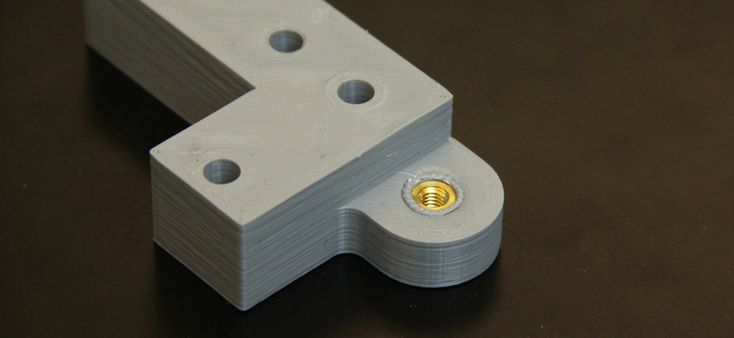 In particular, there is a problem with the buttons, so you have to use either flat touch surfaces that do not give the usual tactile response, or ordinary hard buttons that are uncomfortable to wear on the body.
Engineers led by Rong-Hao Liang of the Technical University of Eindhoven have created a simple method that allows you to embed buttons in clothing, and is based on standard sewing methods. The clothing created by this method consists of two layers of fabric. On the bottom layer, on the inside, it is necessary to embroider a simple electronic circuit, consisting of intersecting, but not touching, conductive threads, embroidered along and across.
On the top layer on the outside, engineers printed with a 3D printer or embroidered with a sewing machine buttons in the form of hexagons with a circle in the middle. As in the case of the bottom layer, before that the fabric was stretched. Due to this, after the button was printed and the fabric stopped stretching, the area of \u200b\u200bthe fabric with the button rose above the rest part and took shape.
The authors pasted thin copper plates onto the inside of the button layer. When the user presses the button, the plate comes into contact with two intersecting conductive traces of the adjacent layer, and a circuit is closed, which is registered by the Arduino board connected to them.
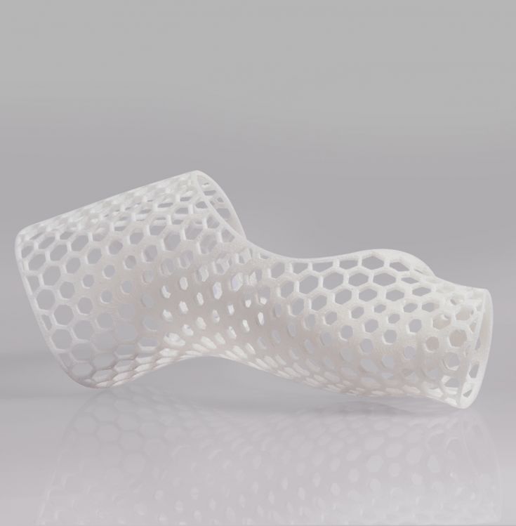
For example, the authors sewed a sleeve with an array of hexagonal buttons: such a sleeve can track pressing both individual buttons and several buttons at the same time in real time.
Recently, American engineers have learned how to create clothes with dozens of temperature and motion sensors. It has strips with conductive paths and sensors hidden from others between layers of fabric. Data from them is collected by a small device that is fastened to clothing through ordinary fasteners.