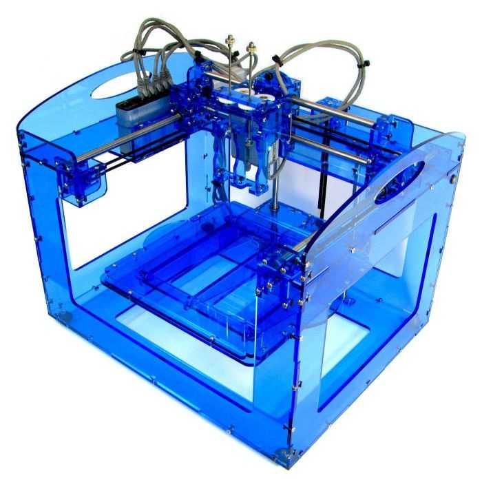
Design and fabrication of 3d printer
What is 3D printing? How does a 3D printer work? Learn 3D printing
3D printing or additive manufacturing is a process of making three dimensional solid objects from a digital file.
The creation of a 3D printed object is achieved using additive processes. In an additive process an object is created by laying down successive layers of material until the object is created. Each of these layers can be seen as a thinly sliced cross-section of the object.
3D printing is the opposite of subtractive manufacturing which is cutting out / hollowing out a piece of metal or plastic with for instance a milling machine.
3D printing enables you to produce complex shapes using less material than traditional manufacturing methods.
Table of Contents
- How Does 3D Printing Work?
- 3D Printing Industry
- Examples of 3D Printing
- 3D Printing Technologies & Processes
- Materials
- Services
Jump to your field of interest:
- Rapid Prototyping & Manufacturing
- Automotive
- Aviation
- Construction
- Consumer Products
- Healthcare
- Food
- Education
Jump to process:
- All Technologies & Processes
- Vat Photopolymerisation
- Material Jetting
- Binder Jetting
- Material Extrusion
- Powder Bed Fusion
- Sheet Lamination
- Directed Energy Deposition
How Does 3D Printing Work?
It all starts with a 3D model. You can opt to create one from the ground up or download it from a 3D library.
3D Software
There are many different software tools available. From industrial grade to open source. We’ve created an overview on our 3D software page.
We often recommend beginners to start with Tinkercad. Tinkercad is free and works in your browser, you don’t have to install it on your computer. Tinkercad offers beginner lessons and has a built-in feature to export your model as a printable file e.g .STL or .OBJ.
Now that you have a printable file, the next step is to prepare it for your 3D printer. This is called slicing.
Slicing: From printable file to 3D Printer
Slicing basically means slicing up a 3D model into hundreds or thousands of layers and is done with slicing software.
When your file is sliced, it’s ready for your 3D printer. Feeding the file to your printer can be done via USB, SD or Wi-Fi. Your sliced file is now ready to be 3D printed layer by layer.
3D Printing Industry
Adoption of 3D printing has reached critical mass as those who have yet to integrate additive manufacturing somewhere in their supply chain are now part of an ever-shrinking minority. Where 3D printing was only suitable for prototyping and one-off manufacturing in the early stages, it is now rapidly transforming into a production technology.
Most of the current demand for 3D printing is industrial in nature. Acumen Research and Consulting forecasts the global 3D printing market to reach $41 billion by 2026.
As it evolves, 3D printing technology is destined to transform almost every major industry and change the way we live, work, and play in the future.
Examples of 3D Printing
3D printing encompasses many forms of technologies and materials as 3D printing is being used in almost all industries you could think of. It’s important to see it as a cluster of diverse industries with a myriad of different applications.
A few examples:
- – consumer products (eyewear, footwear, design, furniture)
- – industrial products (manufacturing tools, prototypes, functional end-use parts)
- – dental products
- – prosthetics
- – architectural scale models & maquettes
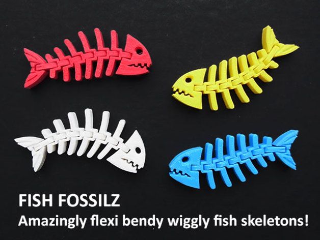
- – reconstructing fossils
- – replicating ancient artefacts
- – reconstructing evidence in forensic pathology
- – movie props
Rapid Prototyping & Rapid Manufacturing
Companies have used 3D printers in their design process to create prototypes since the late seventies. Using 3D printers for these purposes is called rapid prototyping.
Why use 3D Printers for Rapid Prototyping?
In short: it’s fast and relatively cheap. From idea, to 3D model to holding a prototype in your hands is a matter of days instead of weeks. Iterations are easier and cheaper to make and you don’t need expensive molds or tools.
Besides rapid prototyping, 3D printing is also used for rapid manufacturing. Rapid manufacturing is a new method of manufacturing where businesses use 3D printers for short run / small batch custom manufacturing.
Automotive
Car manufacturers have been utilizing 3D printing for a long time. Automotive companies are printing spare parts, tools, jigs and fixtures but also end-use parts. 3D printing has enabled on-demand manufacturing which has lead to lower stock levels and has shortened design and production cycles.
Automotive enthusiasts all over the world are using 3D printed parts to restore old cars.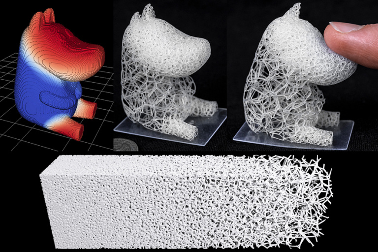 One such example is when Australian engineers printed parts to bring a Delage Type-C back to life. In doing so, they had to print parts that were out of production for decades.
Aviation
The aviation industry uses 3D printing in many different ways. The following example marks a significant 3D printing manufacturing milestone: GE Aviation has 3D printed 30,000 Cobalt-chrome fuel nozzles for its LEAP aircraft engines. They achieved that milestone in October of 2018, and considering that they produce 600 per week on forty 3D printers, it’s likely much higher than that now.
Around twenty individual parts that previously had to be welded together were consolidated into one 3D printed component that weighs 25% less and is five times stronger. The LEAP engine is the best selling engine in the aerospace industry due to its high level of efficiency and GE saves $3 million per aircraft by 3D printing the fuel nozzles, so this single 3D printed part generates hundreds of millions of dollars of financial benefit.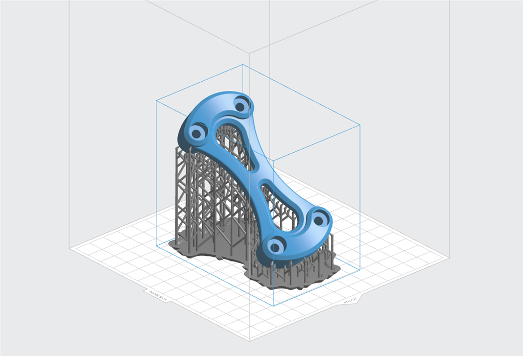
GE’s fuel nozzles also made their way into the Boeing 787 Dreamliner, but it’s not the only 3D printed part in the 787. The 33-centimeter-long structural fittings that hold the aft kitchen galley to the airframe are 3D printed by a company called Norsk Titanium. Norsk chose to specialize in titanium because it has a very high strength-to-weight ratio and is rather expensive, meaning the reduction in waste enabled by 3D printing has a more significant financial impact than compared to cheaper metals where the costs of material waste are easier to absorb. Rather than sintering metal powder with a laser like most metal 3D printers, the Norsk Merke 4 uses a plasma arc to melt a metal wire in a process called Rapid Plasma Deposition (a form of Directed Energy Deposition) that can deposit up to 10kg of titanium per hour.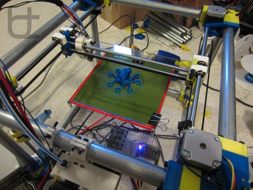 A 2kg titanium part would generally require a 30kg block of titanium to machine it from, generating 28kg of waste, but 3D printing the same part requires only 6kg of titanium wire.
Construction
Is it possible to print a building? – yes it is. 3D printed houses are already commercially available. Some companies print parts prefab and others do it on-site.
Most of the concrete printing stories we look at on this website are focused on large scale concrete printing systems with fairly large nozzles for a large flow rate. It’s great for laying down concrete layers in a fairly quick and repeatable manner. But for truly intricate concrete work that makes full use of the capabilities of 3D printing requires something a little more nimble, and with a finer touch.
Consumer Products
When we first started blogging about 3D printing back in 2011, 3D printing wasn’t ready to be used as a production method for large volumes. Nowadays there are numerous examples of end-use 3D printed consumer products.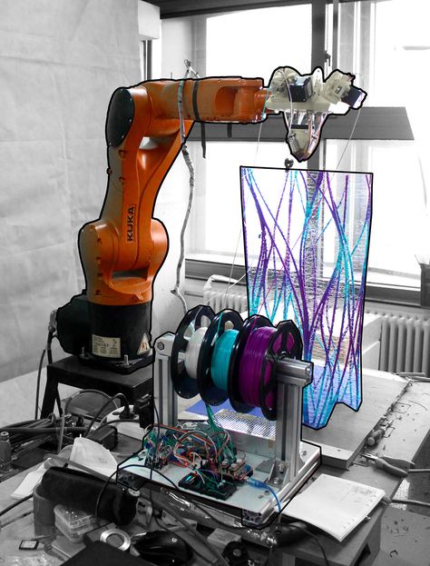
Footwear
Adidas’ 4D range has a fully 3D printed midsole and is being printed in large volumes. We did an article back then, explaining how Adidas were initially releasing just 5,000 pairs of the shoes to the public, and had aimed to sell 100,000 pairs of the AM-infused designs by 2018.
With their latest iterations of the shoe, it seems that they have surpassed that goal, or are on their way to surpassing it. The shoes are available all around the world from local Adidas stores and also from various 3rd party online outlets.
Eyewear
The market of 3D printed eyewear is forecasted to reach $3.4 billion by 2028. A rapidly increasing section is that of end-use frames. 3D printing is a particularly suitable production method for eyewear frames because the measurements of an individual are easy to process in the end product.
But did you know it’s also possible to 3D print lenses? Traditional glass lenses don’t start out thin and light; they’re cut from a much larger block of material called a blank, about 80% of which goes to waste. When we consider how many people wear glasses and how often they need to get a new pair, 80% of those numbers is a lot of waste. On top of that, labs have to keep huge inventories of blanks to meet the custom vision needs of their clients. Finally, however, 3D printing technology has advanced enough to provide high-quality, custom ophthalmic lenses, doing away with the waste and inventory costs of the past. The Luxexcel VisionEngine 3D printer uses a UV-curable acrylate monomer to print two pairs of lenses per hour that require no polishing or post-processing of any kind. The focal areas can also be completely customized so that a certain area of the lens can provide better clarity at a distance while a different area of the lens provides better vision up close.
Jewelry
There are two ways of producing jewelry with a 3D printer. You can either use a direct or indirect production process. Direct refers to the creation of an object straight from the 3D design while indirect manufacturing means that the object (pattern) that is 3D printed eventually is used to create a mold for investment casting.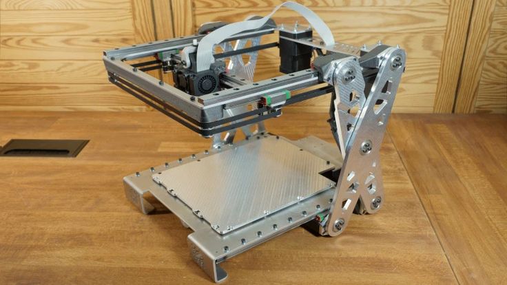
Healthcare
It’s not uncommon these days to see headlines about 3D printed implants. Often, those cases are experimental, which can make it seem like 3D printing is still a fringe technology in the medical and healthcare sectors, but that’s not the case anymore. Over the last decade, more than 100,000 hip replacements have been 3D printed by GE Additive.
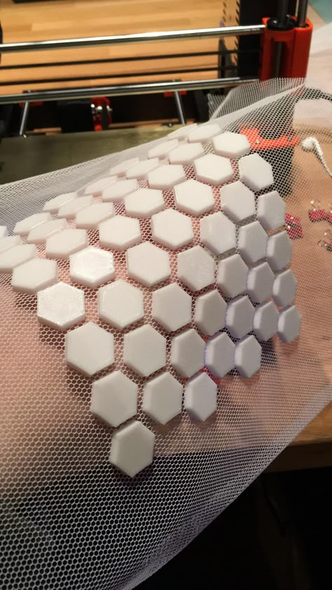
The Delta-TT Cup designed by Dr. Guido Grappiolo and LimaCorporate is made of Trabecular Titanium, which is characterized by a regular, three-dimensional, hexagonal cell structure that imitates trabecular bone morphology. The trabecular structure increases the biocompatibility of the titanium by encouraging bone growth into the implant. Some of the first Delta-TT implants are still running strong over a decade later.
Another 3D printed healthcare component that does a good job of being undetectable is the hearing aid. Nearly every hearing aid in the last 17 years has been 3D printed thanks to a collaboration between Materialise and Phonak.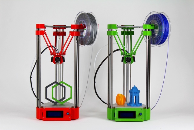 Phonak developed Rapid Shell Modeling (RSM) in 2001. Prior to RSM, making one hearing aid required nine laborious steps involving hand sculpting and mold making, and the results were often ill-fitting. With RSM, a technician uses silicone to take an impression of the ear canal, that impression is 3D scanned, and after some minor tweaking the model is 3D printed with a resin 3D printer. The electronics are added and then it’s shipped to the user. Using this process, hundreds of thousands of hearing aids are 3D printed each year.
Dental
In the dental industry, we see molds for clear aligners being possibly the most 3D printed objects in the world. Currently, the molds are 3D printed with both resin and powder based 3D printing processes, but also via material jetting. Crowns and dentures are already directly 3D printed, along with surgical guides.
Bio-printing
As of the early two-thousands 3D printing technology has been studied by biotech firms and academia for possible use in tissue engineering applications where organs and body parts are built using inkjet techniques. Layers of living cells are deposited onto a gel medium and slowly built up to form three dimensional structures. We refer to this field of research with the term: bio-printing.
Food
Additive manufacturing invaded the food industry long time ago. Restaurants like Food Ink and Melisse use this as a unique selling point to attract customers from across the world.
Education
Educators and students have long been using 3D printers in the classroom. 3D printing enables students to materialize their ideas in a fast and affordable way.
While additive manufacturing-specific degrees are fairly new, universities have long been using 3D printers in other disciplines. There are many educational courses one can take to engage with 3D printing. Universities offer courses on things that are adjacent to 3D printing like CAD and 3D design, which can be applied to 3D printing at a certain stage.
In terms of prototyping, many university programs are turning to printers.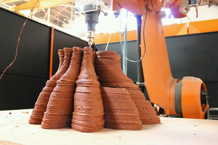 There are specializations in additive manufacturing one can attain through architecture or industrial design degrees. Printed prototypes are also very common in the arts, animation and fashion studies as well.
Types of 3D Printing Technologies and Processes
The American Society for Testing and Materials (ASTM), developed a set of standards that classify additive manufacturing processes into 7 categories. These are:
- Vat Photopolymerisation
- Stereolithography (SLA)
- Digital Light Processing (DLP)
- Continuous Liquid Interface Production (CLIP)
- Material Jetting
- Binder Jetting
- Material Extrusion
- Fused Deposition Modeling (FDM)
- Fused Filament Fabrication (FFF)
- Powder Bed Fusion
- Multi Jet Fusion (MJF)
- Selective Laser Sintering (SLS)
- Direct Metal Laser Sintering (DMLS)
- Sheet Lamination
- Directed Energy Deposition
Vat Photopolymerisation
A 3D printer based on the Vat Photopolymerisation method has a container filled with photopolymer resin.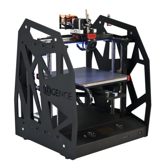 The resin is hardened with a UV light source.
Stereolithography (SLA)
SLA was invented in 1986 by Charles Hull, who also at the time founded the company, 3D Systems. Stereolithography employs a vat of liquid curable photopolymer resin and an ultraviolet laser to build the object’s layers one at a time. For each layer, the laser beam traces a cross-section of the part pattern on the surface of the liquid resin. Exposure to the ultraviolet laser light cures and solidifies the pattern traced on the resin and fuses it to the layer below.
After the pattern has been traced, the SLA’s elevator platform descends by a distance equal to the thickness of a single layer, typically 0.05 mm to 0.15 mm (0.002″ to 0.006″). Then, a resin-filled blade sweeps across the cross section of the part, re-coating it with fresh material. On this new liquid surface, the subsequent layer pattern is traced, joining the previous layer. Depending on the object & print orientation, SLA often requires the use of support structures.
Digital Light Processing (DLP)
DLP or Digital Light Processing refers to a method of printing that makes use of light and photosensitive polymers. While it is very similar to SLA, the key difference is the light source. DLP utilizes other light sources like arc lamps. DLP is relatively quick compared to other 3D printing technologies.
Continuous Liquid Interface Production (CLIP)
One of the fastest processes using Vat Photopolymerisation is called CLIP, short for Continuous Liquid Interface Production, developed by Carbon.
Digital Light Synthesis
The heart of the CLIP process is Digital Light Synthesis technology. In this technology, light from a custom high performance LED light engine projects a sequence of UV images exposing a cross section of the 3D printed part causing the UV curable resin to partially cure in a precisely controlled way.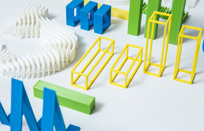 Oxygen passes through the oxygen permeable window creating a thin liquid interface of uncured resin between the window and the printed part known as the dead zone. The dead zone is as thin as ten of microns. Inside the dead zone, oxygen prohibits light from curing the resin situated closest to the window therefore allowing the continuous flow of liquid beneath the printed part. Just above the dead zone the UV projected light upwards causes a cascade like curing of the part.
Simply printing with Carbon’s hardware alone does not allow for end use properties with real world applications. Once the light has shaped the part, a second programmable curing process achieves the desired mechanical properties by baking the 3d printed part in a thermal bath or oven. Programmed thermal curing sets the mechanical properties by triggering a secondary chemical reaction causing the material to strengthen achieving the desired final properties.
Components printed with Carbon’s technology are on par with injection molded parts.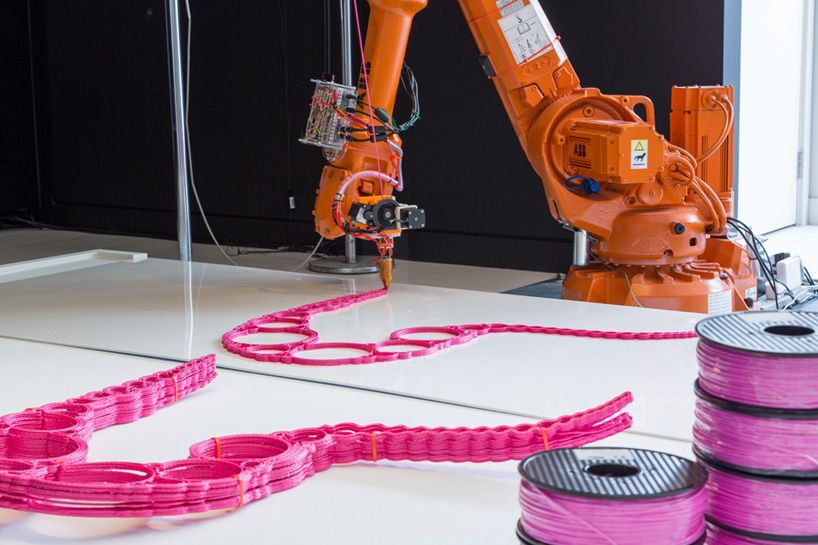 Digital Light Synthesis produces consistent and predictable mechanical properties, creating parts that are truly isotropic.
Material Jetting
In this process, material is applied in droplets through a small diameter nozzle, similar to the way a common inkjet paper printer works, but it is applied layer-by-layer to a build platform and then hardened by UV light.
Material Jetting schematics. Image source: custompartnet.comBinder Jetting
With binder jetting two materials are used: powder base material and a liquid binder. In the build chamber, powder is spread in equal layers and binder is applied through jet nozzles that “glue” the powder particles in the required shape. After the print is finished, the remaining powder is cleaned off which often can be re-used printing the next object. This technology was first developed at the Massachusetts Institute of Technology in 1993.
Binder Jetting schematicsMaterial Extrusion
Fused Deposition Modeling (FDM)
FDM schematics (Image credit: Wikipedia, made by user Zureks)FDM works using a plastic filament which is unwound from a spool and is supplied to an extrusion nozzle which can turn the flow on and off.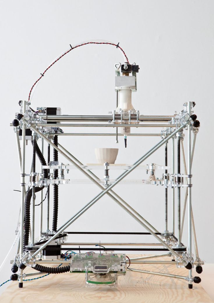 The nozzle is heated to melt the material and can be moved in both horizontal and vertical directions by a numerically controlled mechanism. The object is produced by extruding melted material to form layers as the material hardens immediately after extrusion from the nozzle.
FDM was invented by Scott Crump in the late 80’s. After patenting this technology he started the company Stratasys in 1988. The term Fused Deposition Modeling and its abbreviation to FDM are trademarked by Stratasys Inc.
Fused Filament Fabrication (FFF)
The exactly equivalent term, Fused Filament Fabrication (FFF), was coined by the members of the RepRap project to give a phrase that would be legally unconstrained in its use.
Powder Bed Fusion
Selective Laser Sintering (SLS)
SLS uses a high power laser to fuse small particles of powder into a mass that has the desired three dimensional shape. The laser selectively fuses powder by first scanning the cross-sections (or layers) on the surface of a powder bed.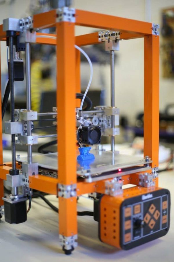 After each cross-section is scanned, the powder bed is lowered by one layer thickness. Then a new layer of material is applied on top and the process is repeated until the object is completed.
Multi Jet Fusion (MJF)
Multi Jet Fusion technology was developed by Hewlett Packard and works with a sweeping arm which deposits a layer of powder and then another arm equipped with inkjets which selectively applies a binder agent over the material. The inkjets also deposit a detailing agent around the binder to ensure precise dimensionality and smooth surfaces. Finally, the layer is exposed to a burst of thermal energy that causes the agents to react.
Direct Metal Laser Sintering (DMLS)
DMLS is basically the same as SLS, but uses metal powder instead. All unused powder remains as it is and becomes a support structure for the object. Unused powder can be re-used for the next print.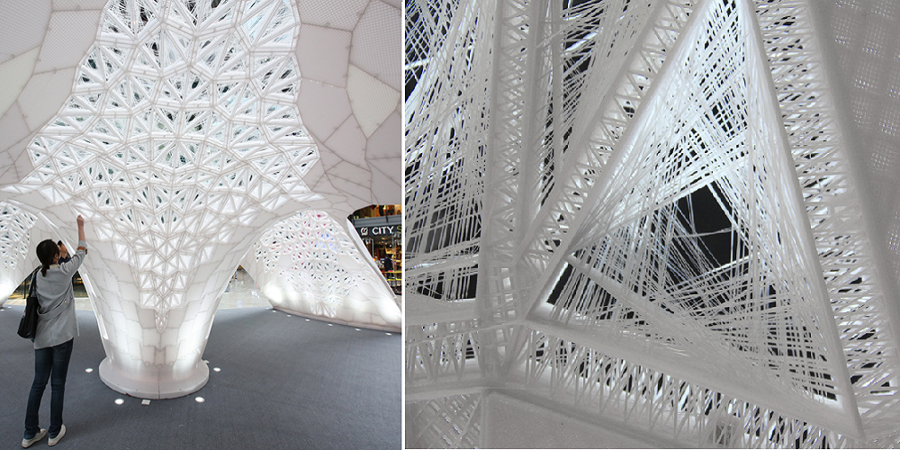
Due to of increased laser power, DMLS has evolved into a laser melting process. Read more about that and other metal technologies on our metal technologies overview page.
Sheet Lamination
Sheet lamination involves material in sheets which is bound together with external force. Sheets can be metal, paper or a form of polymer. Metal sheets are welded together by ultrasonic welding in layers and then CNC milled into a proper shape. Paper sheets can be used also, but they are glued by adhesive glue and cut in shape by precise blades.
Simplified schematics of ultrasonic sheet metal process (Image credit: Wikipedia from user Mmrjf3)Directed Energy Deposition
This process is mostly used in the metal industry and in rapid manufacturing applications. The 3D printing apparatus is usually attached to a multi-axis robotic arm and consists of a nozzle that deposits metal powder or wire on a surface and an energy source (laser, electron beam or plasma arc) that melts it, forming a solid object.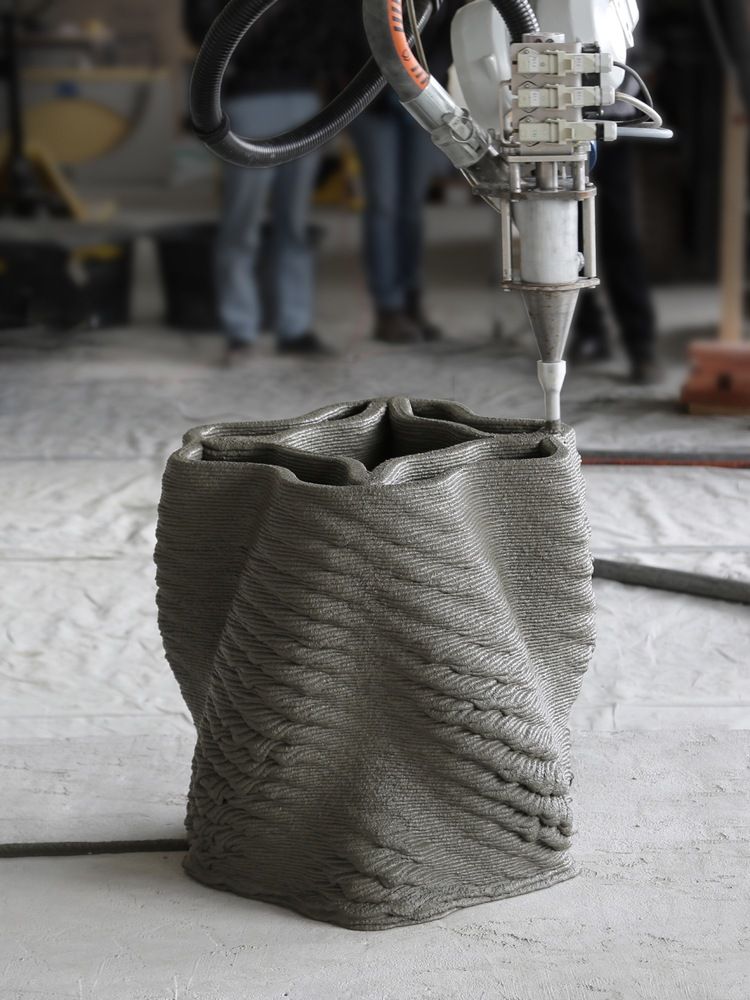
Materials
Multiple materials can be used in additive manufacturing: plastics, metals, concrete, ceramics, paper and certain edibles (e.g. chocolate). Materials are often produced in wire feedstock a.k.a. filament, powder form or liquid resin. Learn more about our featured materials on our materials page.
Services
Looking to implement 3D printing in your production process? Get a quote for a custom part or order samples on our 3D print service page.
Digital Fabrication 101
Digital fabrication is a design and manufacturing workflow where digital data directly drives manufacturing equipment to form various part geometries. This data most often comes from CAD (computer-aided design), which is then transferred to CAM (computer-aided manufacturing) software. The output of CAM software is data that directs a specific additive and subtractive manufacturing tool, such as a 3D printer or CNC milling machine.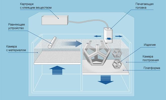
A wide variety of digital fabrication tools exist, from hobbyist-level machines to large-scale, specialized industrial equipment used in manufacturing. This guide focuses on the most common tools suitable for professional workspaces, machine shops, and workshops.
Accessible digital fabrication tools bridge the gap between design and manufacturing. As barriers to professional-level tech lowers, it’s easier for anyone with the skills to design a product to also fabricate it, empowering engineers, product designers, and businesses of all sizes to produce anything from prototypes to final products.
In this definitive guide, learn the ins and outs of digital fabrication from workflows to digital fabrication tools and practical tips for getting started.
Webinar
In this webinar, learn how parts created from various printing technologies differ across functionality and appearance, and how these differences impact product development and production workflows for engineers and manufacturers.
Watch the Webinar
The first step is to create a digital design using CAD software. To serve as input for the fabrication tool, the 3D model is exported as a triangulated mesh, which uniformly describes the geometry in terms of points on the surface or vertices, the faces between those vertices, the edges of those faces, and in some cases, the normal vectors and color information pertaining to the faces.
Print preparation software or slicer software serves as the intermediate between the virtual mesh and the fabricated model for 3D printing. In this step, manufacturing parameters and settings specific to the fabrication tool are added to provide essentially a list of instructions for the machine to follow, resulting in a CAM file that’s sent to the machine. In machining operations, software simulation is combined with user input to generate toolpaths that will guide the cutting tool through the part geometry, taking into account speed of the cutting tool and feed rate of the material.
Fabrication tools manufacture parts based on the CAM data, with little or no human assistance or interaction. The fabricated parts might require some form of finishing to achieve their final properties and look before they’re ready to use.
Additive manufacturing (AM) or 3D printing processes create parts by successively adding material layer by layer until a physical part is created.
Fused deposition modeling (FDM) 3D printers melt and extrude thermoplastic filament, which a print nozzle then deposits layer by layer in the build area. FDM is the most affordable 3D printing technology with entry-level hobbyist machines starting below $1,000, and mid-range machines selling for $2,500. FDM parts have the lowest resolution and accuracy compared to other plastic 3D printers, making these machines a better fit for basic proof-of-concept models and quick, low-cost prototyping of simple parts than for refined prototypes or final products.
Stereolithography (SLA) uses a laser to cure liquid resin into hardened plastic in a process called photopolymerization.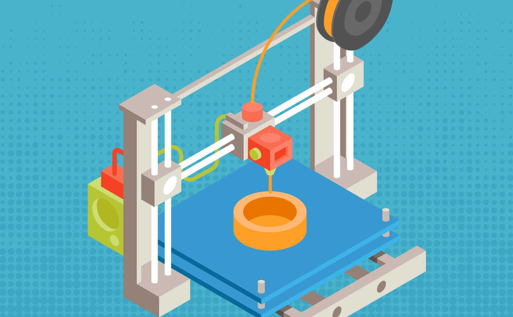 SLA parts are highly accurate, have fine details, smooth surface finish, and isotropic material properties. SLA 3D printing is ideal for complex designs, functional prototypes, manufacturing tooling, and casting patterns. Starting around $3,750, desktop SLA printers are highly versatile tools that are easy to use and accessible to professional users.
See how stereolithography works.
Selective laser sintering (SLS) 3D printers use a high-powered laser to fuse small particles of polymer powder. The unfused powder supports the part during printing and eliminates the need for dedicated support structures. Parts produced with SLS printing have excellent mechanical characteristics, with strength comparable to injection-molded parts. SLS is the latest plastic 3D printing technology to appear in a smaller, more accessible form, with benchtop systems starting around $19,000.
| Fused Deposition Modeling (FDM) | Stereolithography (SLA) | Selective Laser Sintering (SLS) | |
|---|---|---|---|
| Accuracy | ★★★★☆ | ★★★★★ | ★★★★★ |
| Surface Finish | ★★☆☆☆ | ★★★★★ | ★★★★☆ |
| Complex Designs | ★★★☆☆ | ★★★★☆ | ★★★★★ |
| Ease of Use | ★★★★★ | ★★★★★ | ★★★★☆ |
| Materials | Standard thermoplastics, such as ABS, PLA, and their various blends | Varieties of resin (thermosetting plastics), ABS-like, PP-like, flexible, heat-resistant, castable (wax-like) | Engineering thermoplastics, such as nylon and its composites |
| Applications | Low-cost rapid prototyping Basic proof-of-concept models | Functional prototyping Manufacturing tooling Casting Modelmaking | Functional prototyping Short-run, bridge, or custom manufacturing |
Read our in-depth guide to compare of FDM, SLA, and SLS technologies.
Video Guide
Having trouble finding the best 3D printing technology for your needs? In this video guide, we compare FDM, SLA, and SLS technologies across popular buying considerations.
Watch the Videos
Sample part
See and feel Formlabs quality firsthand. We’ll ship a free sample part to your office.
Request a Free Sample Part
Subtractive processes start with solid blocks, bars, or rods of plastic, metal, or other materials that are shaped by removing material through cutting, boring, drilling, and grinding. In digital fabrication processes, these tools are driven by computer numerical control (CNC).
CNC machining removes material by either a spinning tool and fixed part (milling) or a spinning part with a fixed tool (lathe). Small CNC machines start around $2,000, but more advanced workshop tools go well beyond that depending on the number of axes, features, part size, and tooling needed for specific materials.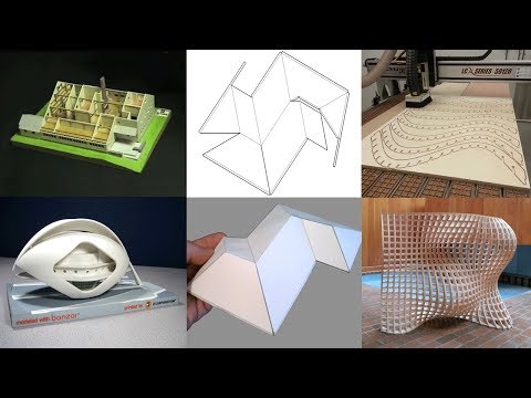 CNC machines can create parts out of plastics and metals for functional prototyping, manufacturing tooling, and custom or low-volume end-use parts.
Laser cutters use a laser to engrave or cut through a wide range of materials with high precision. Laser cutters are cost-effective, fast, and easy-to-use tools for engraving and cutting thin, flat-sheet materials for prototypes, mechanical and structural parts. Basic engravers are available for less than $500, while mid-range laser cutters for the workshop that can cut through multiple materials start around $3,500. Laser cutters are often bundled with a driver software which interprets 2D vector drawings.
Water jet cutters use water mixed with abrasive and high pressure to cut through practically any material. Water jet cutting is the latest CNC process to appear in a smaller, more accessible form with prices starting around $20,000, and new projects promise to soon push below $10,000. Water jet cutters can cut thicker sheets than laser cutters and work with hard materials that are normally difficult to cut to the precise shapes using other processes.
| CNC Machining | Laser Cutters | Water Jet Cutters | |
|---|---|---|---|
| Accuracy | ★★★★★ | ★★★★★ | ★★★★★ |
| Surface Finish | ★★★★★ | ★★★★★ | ★★★★★ |
| Complex Designs | ★★★★☆ | ★☆☆☆☆ | ★☆☆☆☆ |
| Ease of Use | ★★★☆☆ | ★★★★☆ | ★★★☆☆ |
| Materials | Hard thermoplastics, soft thermoset plastics (limited), soft metals, hard metals (industrial machines) | Thermoplastics, wood, acrylic, fabrics, metals (industrial machines) | Plastics, hard and soft metals, stone, glass, composites |
| Applications | Functional prototyping Manufacturing tooling Custom or low-volume end-use parts | Engraving Prototyping Flat mechanical and structural parts | Prototyping Flat mechanical and structural parts |
To convert an idea to a digital design, there are several approaches:
Solid modeling is a traditional way of creating 3D objects that is mostly geared towards linear motions to translate design intent into geometries. Solids are combined and finished with transitions to make them directly suitable for digital manufacturing. Advanced features include drafted extrusions, curvature fillets, and patterning operations.
Surface modeling can be performed in most contemporary solid modeling software such as Autodesk Fusion 360, Solidworks, Catia, Rhinoceros, and SolidEdge. In this case, all outside surfaces of the geometry are individually defined, enabling more advanced geometries such as transitions between multiple adjoining surfaces.
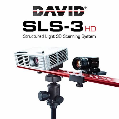
3D scanning has become an accessible route to obtaining a 3D printable model. Affordable solutions and new apps that work with camera-based photogrammetry technology provide a great balance between speed, accuracy, and cost. However, scans don’t translate to 3D printable files directly and require extensive post-editing with mesh editing software.
Two-dimensional systems such as CNC routers and laser cutters can be driven by files exported from vector software such as Adobe Illustrator. Although a fairly comprehensive package, for basic drawing you do not need very advanced skills beyond a familiarity with the pen tool, patterning, live trace, Pathfinder, and a plugin to create rounded corners.
A 3D model leaving a design software package as a mesh model is typically suited for 3D printing already. The key is having a watertight mesh, meaning all triangles are connected and non-overlapping with normals facing the same direction. A solid modeling approach usually results in a watertight mesh, surface modeling, and generative design though require checking the absence of double surfaces and volume collisions.
There are plenty of tools to repair and optimize meshes, such as Meshlab. Ideally, make a small investment in a tool that allows you to edit individual vertices/faces and perform Boolean tasks. Meshmixer is a great free program for optimizing triangle count and allows resculpting your object as well, while Blender allows Boolean operations.
While digital fabrication tools offer a high degree of design freedom, a bit of time spent on optimizing part geometries goes a long way to ensure efficient production and high-quality parts.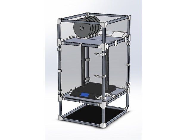 Make sure to comprehensively study the possibilities and limitations of the machine, material, design software and fabrication process that you are planning to use. Find the time to extensively experiment towards goals that you want to achieve before diving in head-first.
3D printers are easy to use and accessible digital fabrication tools for personal workspaces, machine shops, and workshops.
Learn more about 3D printing and see the quality firsthand by requesting a complimentary sample part printed on a Form 3+ SLA 3D printer or Fuse Series SLS 3D printer.
Request a Free Sample Part
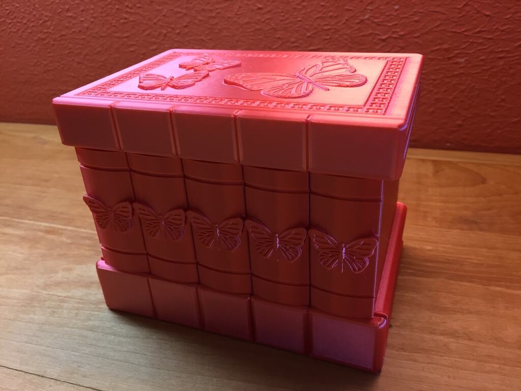
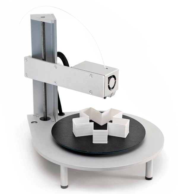
Designing a Personal 3D Printer
Unfortunately, the cost of ready-made 3D printers is very high, and the models of 3D printers available as DIY kits are not rigid in terms of construction. At the same time, more attention should be paid to the issues of reducing the cost of the design while maintaining the high performance properties of the printer as much as possible. Therefore, the development of a personal 3D printer that can be assembled on its own with minimal financial costs is an urgent problem.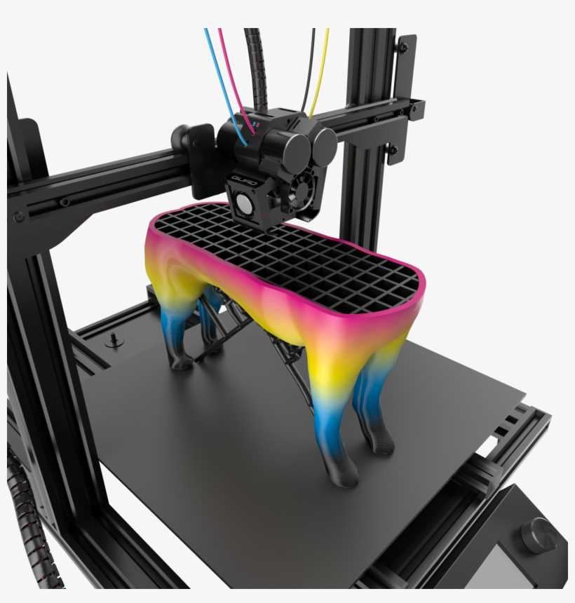
Purpose
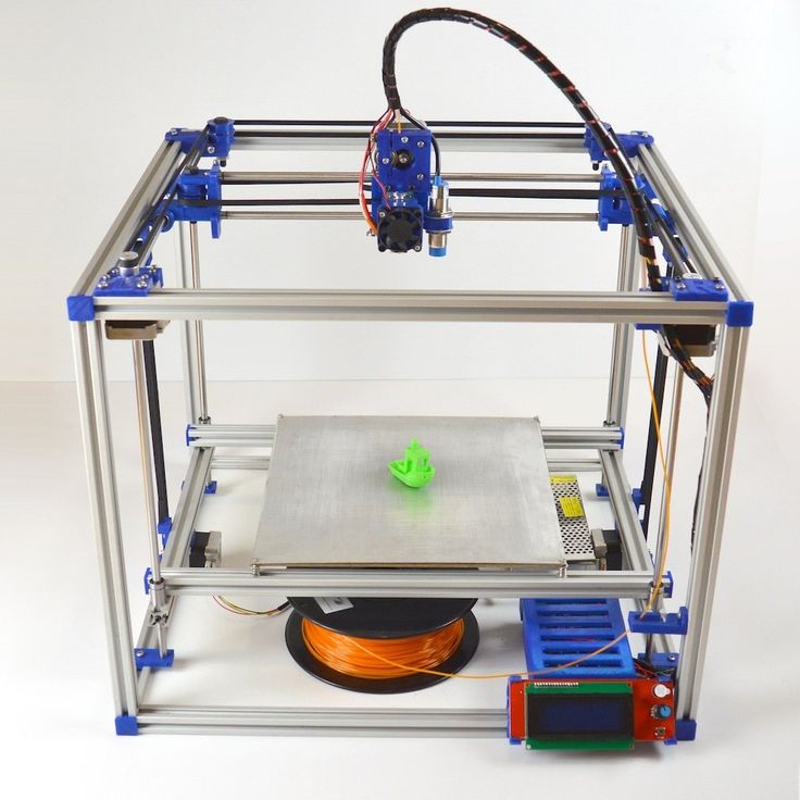
Development and construction of an FDM technology 3D printer with specified technical characteristics and low production cost.
Tasks
1. Analyze the existing designs of 3D printers.
2. Determine the specifications of the 3D printer.
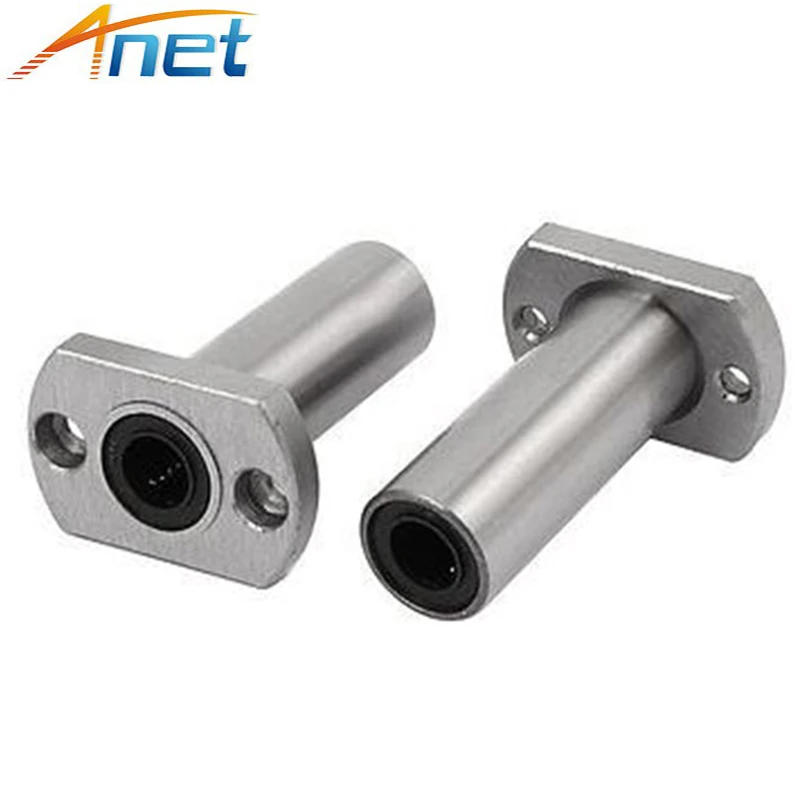
3. Select accessories.
4. Create a 3D model of the printer structure.
5. Produce the necessary parts.
6. Assemble the 3D printer.
7. Set up the firmware.
8. Perform a test print.
9. Analyze the resulting structure.
Equipment used to create the work
Accessories:
-
Stepper motors
-
Control board
-
LCD display
-
Power supply
-
Axles
-
Timing belts
-
Pulleys
Equipment:
-
3D printer Magnum Creative 2 Pro
-
Milling machine Optimum BF20CNC
-
Lathe Optimum TU2406CNC
Description
For each of the components of the 3D printer, 3D models were created in the Compass-3D software package.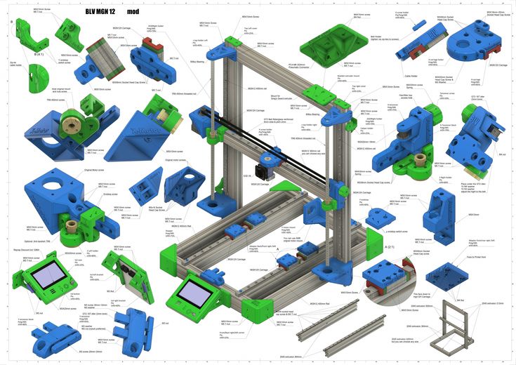 The models were then assembled into a 3D assembly of the future printer.
Part of the parts (mainly body parts) was supposed to be manufactured independently, both using 3D printing technologies and by machining. Parts drawings were created for machining, and for 3D printing, existing models were processed in the Repetier Host slicer program. The assembly of the 3D printer was carried out in the sequence indicated on the block diagram.
Results/Conclusions
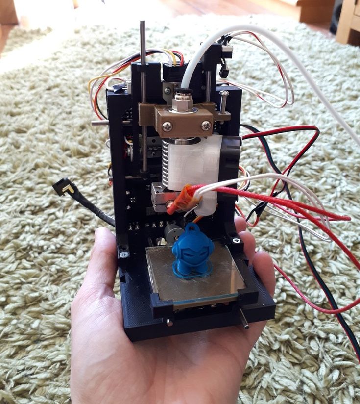
The result of the project is a working 3D printer prototype.
The overall design of the printer needs to be improved: the body parts need to be made in a simpler way. The components used proved to be quite reliable. Plastic shrinkage must be considered when designing printed parts. The design of the table needs to be redesigned in order to provide greater rigidity. For future modifications of printers, it is necessary to conduct operational tests of the built 3D printer model. The cost of manufacturing a printer can be reduced by ordering components at wholesale prices in the case of small-scale production.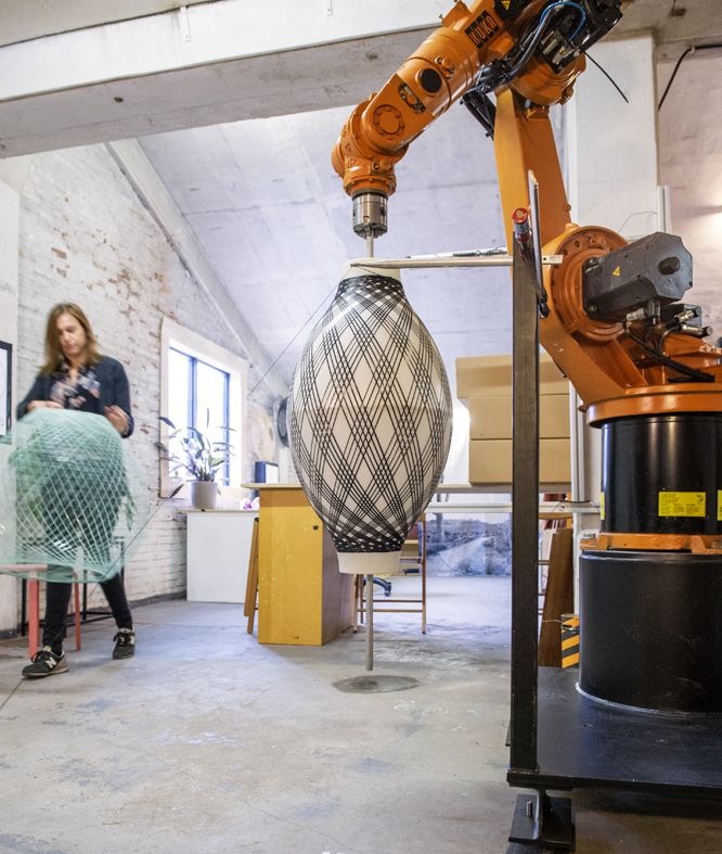
Prospects for using the results of the work
For further use of the assembled printer, it is necessary to obtain data during trial operation. These data will allow us to take into account the advantages and disadvantages of the design when designing the next 3D printer model. Further development of the project will make it possible to create a reliable, accurate and cheap 3D printer to manufacture and operate.
Collaboration with a university/institution in the creation of a job
Moscow Automobile and Highway State Technical University, Department of Production and Repair of Automobiles and Road Machines.
Author's opinion
“The project was carried out at the MADI department, and it was a useful experience. Work will continue next year.”
3D Printed Mounting and Mounting Jig Design
Brief Information
This white paper describes the principles for creating efficient mounting and mounting fixtures, with a focus on how to use 3D printing to reduce costs, reduce development time and creating more efficient manufacturing processes for applications ranging from design engineers to manufacturing technicians
Introduction
For manufacturers, maximum production speed while maintaining high quality parts is critical to success.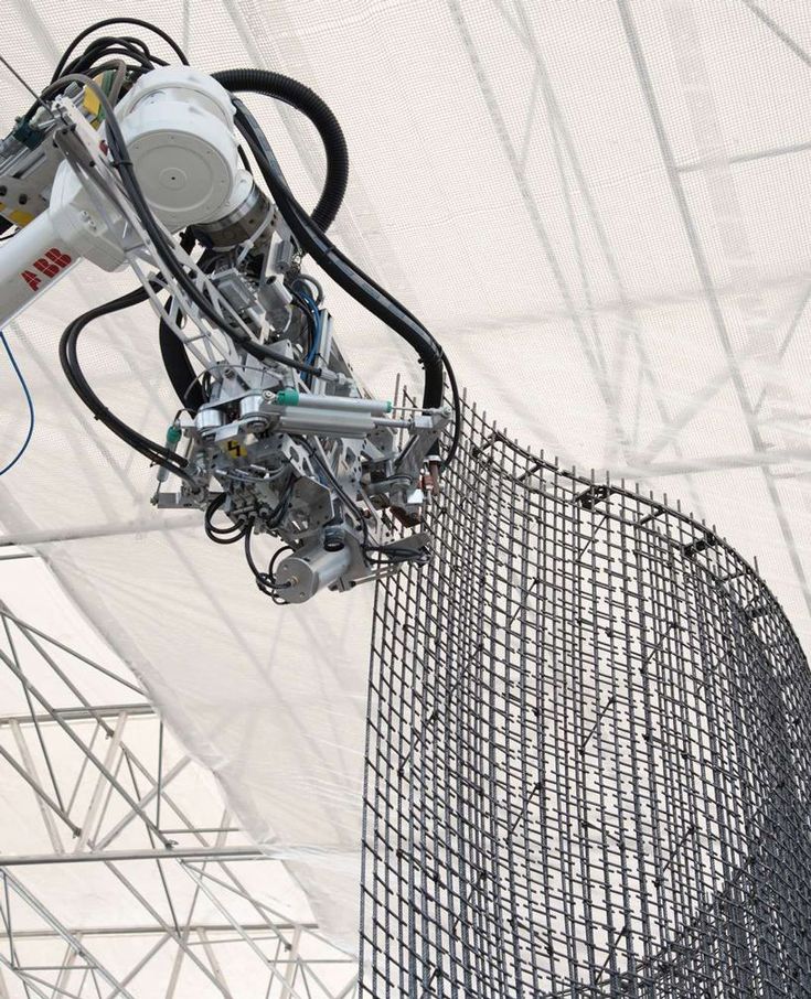 Mounting and installation fixtures are used to simplify and increase the reliability of manufacturing and assembly processes, reduce cycle times and improve worker safety. In this paper, we will explain the basic design principles and concepts of fixtures and fittings, look at how to adapt the characteristics of machined fasteners to achieve successful 3D printing, and discuss how to use the unique advantages of stereolithography (SLA) materials to reduce manufacturing costs. manufacturing and reducing lead time.
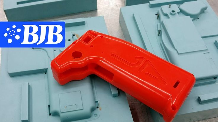
As a rule, manufacturers create metal tools as needed, either machining them in-house or outsourcing. Depending on the loads experienced by the part, it may not always be necessary to manufacture these tools from metal. SLA 3D printing materials have improved significantly and there are a number of functional resins well suited for 3D printing of mounting fixtures, such as primarily Formlabs Standard resins and Formlabs engineering resins, especially Tough, Durable and High Temp.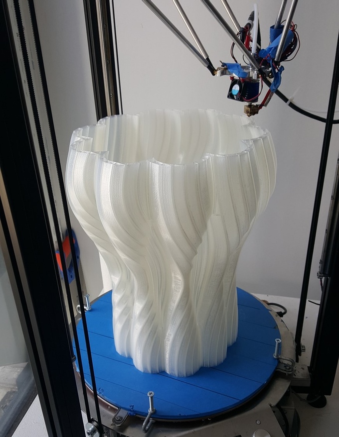 Manufacturers around the world use these materials to replace metal fasteners in automated machines, electronics assembly lines, foundries and other manufacturing facilities
3D printed fasteners on an automated production line at Pankl Racing Systems.
Mounting and setting fixture design fundamentals
UNDERSTANDING THE DEGREE OF FREEDOM AND LIMITATIONS
In their most basic form, mounting and setting fixtures hold a part in position while simultaneously withstanding forces from a secondary operation without subjecting the part being held to an unacceptable force. deviation, movement or rotation. To understand how this is achieved, one must first understand how degrees of freedom work.
A rigid body in space has six degrees of freedom: up/down movement, left/right movement, forward/backward movement, and the ability to rotate along one or more axes called pitch, rotation, and deflection.
Part with all six degrees of freedom.
The principles of good fastener design require that these degrees of freedom be limited as much as possible in order to achieve precise location and safe secondary operations. It is equally important not to overdo this detail. Excessive constraints introduce unnecessary effort and precision issues, requiring higher precision on mounting and setting fixtures.
To explain this principle, consider a stool. A three-legged stool has just the right number of restrictions: when loaded with a weight on its top surface, the chair cannot move vertically. Friction prevents the chair from sliding in any direction, and each leg is limited by the others to prevent individual legs or the entire stool from rotating.
- An exact constraint is when each degree of freedom requires one constraint to work properly.
- An unacceptable deflection occurs when a part is free to rotate, move, or slide in one or more directions or along one or more axes. When secured, underconstraining the part prevents proper operation and can be a significant hazard to machine operators and equipment.
 However, depending on the application, some tasks may need to be under-constrained: for example, a wooden board that can move freely through a planer.
- Insufficiently supported parts have sufficient restraints to prevent movement and rotation of the object, but not enough support to prevent significant deflection of the part during secondary operations such as milling and drilling
- Overlimiting occurs when a structure has excessive limiting factors. One example is that when multiple forces are working to do the same work, those forces will come into conflict and one of these forces will always "win" and end up doing the intended work. Back-up forces at best do nothing or at worst degrade the intended function of the structure, resulting in degraded parts and increased risk to the operator.
In practice, it is sometimes necessary to use too many "limits".
The four-legged chair is an example of overdesign. The fourth leg is redundant and introduces a new rocking problem if it rests on a surface that is even slightly uneven.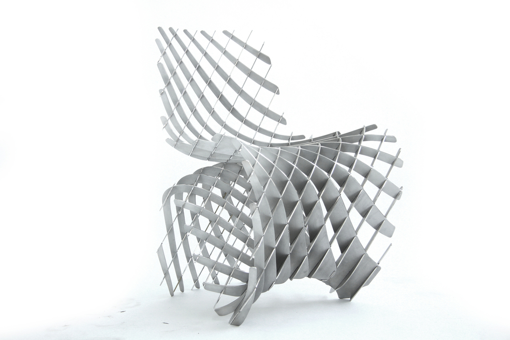
The trade-off is greater overall stability at the expense of the need for flatter floors. To put this into a manufacturing context, a more forgiving (less constrained) fixture design is useful for machining parts that have more variation (castings, for example), while a tighter fixture will work better for parts with more precise surfaces (machined). or injection molding parts).
3D fastener attached to the mounting plate.
3D Printed Mounting and Mounting Jigs
Improved development tools have allowed engineers to create products optimized for end use, but the same design freedom and increased complexity of parts make it difficult to assemble mounting and mounting fixtures for secondary operations. Traditional fastening systems such as vices and clamps cannot provide and support amorphous shapes or components with very fine detail. 3D printing allows engineers to create objects without the limitations such as tool access and wear and tear that come with machining.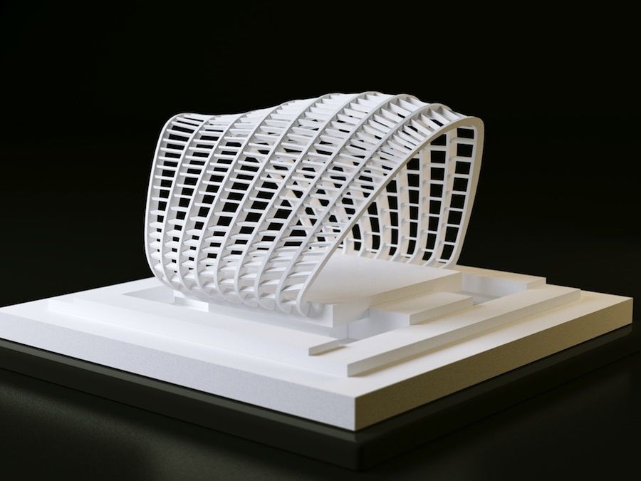
Making fixtures and fittings in an additive process saves significant time and costs by eliminating the skilled labor steps involved in machining solid workpieces or tools for pipe and sheet metal fabrication. Even if fixtures require metal components for end applications, affordable, low-cost 3D printing allows fabrication engineers to test these concepts before building stronger fixtures.
In particular, for parts with curved or complex surfaces, the cost of in-house 3D printing is significantly less than for outsourced milling, even for low-cost plastics such as HDPE. High resolution Formlabs 3D printers with excellent surface finish are well suited for creating mounts and fixtures with curved surfaces and thin objects.
| COST OF SIMPLE FASTENING | Aluminum milling | HDPE milling | Tough Resin Printing |
| Price | $475 | $360 | $46 |
| Run time | 3 – 5 days | 3 – 5 days | print less than 1 day |
Applications for 3D printed mounting and mounting fixtures
SOFT VISE JAWS
Soft jaws are designed to precisely fit the unique geometry of the specific part, allowing you to work on more complex parts and prevent crushing of softer metal or plastic parts.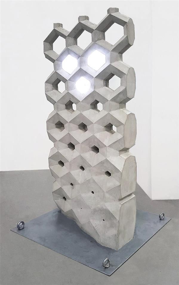 3D printing works well for making soft jaws and jigs due to its high assembly speed and low manufacturing cost for processing complex shapes.
The part is clamped between soft jaws printed with Formlabs Tough Resin.
PILOT DRILLS
Pilot drills help prevent drill deflection or backlash while maintaining angular and spur tolerance requirements
Permanent bushing in Forms Tough Relabins drill template.
Drill guide bushings are available in press-fit or screw-in options and are available from industrial suppliers such as McMaster-Carr Bushings and have been designed specifically for use in plastics, best suited for SLA printed templates
Use the tolerance recommendations in our Design Fit Information Booklet to determine the correct hole size for a press fit.
LIMIT GAUGE
A simple tolerance check using a template or gauge can quickly help a quality control inspector determine if a part will work for its end use.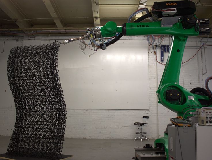 Limit gauge 3D printing is useful when the successful function of parts is determined by small differences in shape and dimension, and these measurements cannot be easily or quickly assessed with calipers, micrometers, or other standard metrology tools, as is the case with complex polymer parts.
Limit gauge for testing rubber gasket printed with Formlabs Clear Resin.
TIP
In some applications, calibers can wear out over time, causing QC to fail.
Due to their low cost and ease of manufacture, 3D printed gauges can be easily reprinted and replaced according to a predetermined schedule or as needed to prevent quality degradation due to worn gauges. This is most noticeable when the parts that are in contact with the limit gauges are hard metals.
ASSEMBLY DRIVER
For many products, the most time-consuming part of the process is joining parts and adding fasteners to create sub-assemblies or complete assemblies.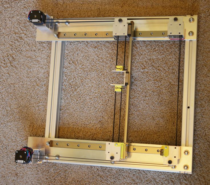 3D printing of part-specific assembly mandrels shortens cycle times, improves workflow ergonomics for assembly technicians, and improves consistency across manufacturing departments errors or gaining access to the device for repairs and modifications. Using a disassembly tool speeds up this process and reduces the risk of breakage. For example, separating a latched housing requires each of the latches to open at the same time to prevent damage to parts.
Formlabs White Resin Clip-on Enclosure Disassembly Tool.
GLUER TOOL
The use of 3D printed glue tools and fasteners is an attractive solution because their low cost makes the regular replacement associated with their use more acceptable.
The adhesive is applied to the part in an adhesive fixture printed with Formlabs Durable Resin.
TIP
Coating the bonding tool with release agent will make it easier to clean up any hardened adhesive that may spill onto the tool.
MARKING AND MASKING TEMPLATES
3D printed fixtures are useful for low force applications; for example, to make sure the label is in the same place on multiple devices, or to mask an area to label.
Using Formlabs Flexible Resin, a consistent masking pattern can be designed to perfectly match the surface of the part. For applications where a stiffer template is required, Durable Resin also works quite well.
Hinged attachment for applying volumetric marks printed with Formlabs Tough Resin and Durable Resin.
SUBSTITUTE PARTS
Replacement parts are typically used to test fixtures or workpieces until fasteners and fixtures are installed in front of final production parts, so that production and assembly lines can get up and running faster and fix process disturbances before effects occur. production.
Replacement parts enable process validation with low cost 3D printed products instead of risking high value sensitive components such as electronics assemblies.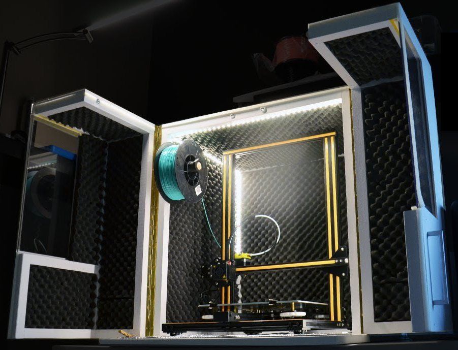
SLA works well for replacement parts due to its high dimensional accuracy and ability to replicate thin objects related to manufacturing or usability issues that FDM or other printing processes can skip. Also, since SLA printed parts are highly isotropic, they will behave similarly to their injection molded counterparts, unlike FDM anisotropic parts.
Recommendations for designing and using 3D printed fasteners
COMPLEXITY (NEARLY) FREE
Since 3D printing allows “free” complexity (increased complexity does not increase the cost of the part), it will take some time to consider what additional features can be built into a fastener or fixture at the design stage to take advantage of this principle. Small objects that are difficult to machine, as well as geometries that are considered impossible due to tool clearance during milling or turning, are included in the scope of additive processes. Serial numbers, manufacturing dates and other relevant data can be embedded into this part for digital asset management and easy tracking without the need for secondary engraving steps.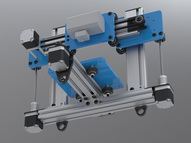
What are usually two components in mechanical equipment can be built into one piece, helping to prevent dust or chips from accumulating by eliminating the gap.
For example, instead of using inserted straight dowels or cylinders to accommodate the part, spherical or diamond structures are built into a single gapless part. The use of diamond or spherical fixtures reduces or eliminates binding of parts during loading and unloading by minimizing the contact area.
Minimum contact mounting fixture printed in Formlabs Tough Resin.
INTRODUCTION OF POINTS IN MOUNTING AND INSTALLATION TOOLS
Part of the process of introducing mounting and installation fixtures in the context of assembly or production checks the dimensional accuracy of fixtures. Amorphous part structures, which 3D printed fixtures are often designed to solve, can be fixtures, and the fixtures themselves tend towards more complex shapes. These designs can be difficult to verify with standard metrology tools such as calipers and micrometers. Creating basic functions in printing devices and fixtures makes inspection easier and more accurate.
A reference point is a theoretically geometric perfect reference—a perfectly flat plane, the axis of a cylindrical hole, etc. The fiducial point object is the reality of this concept in the context of a part that is used as the main reference point for other measurements. Fiducial objects should relate to the requirements of secondary operations and to the functional requirements of the part in the end use.
Where possible, include planar faces or corner geometry in the fixture to aid inspection and determine overall accuracy. With any fixture, accuracy is assessed when parts are inspected after machining, as operating conditions such as part or tool deflection can create errors that require redesign of the mounting and setting fixture.
In applications where accuracy is paramount, use digital metrology tools such as 3D scanners or touch probes to test more organic geometries.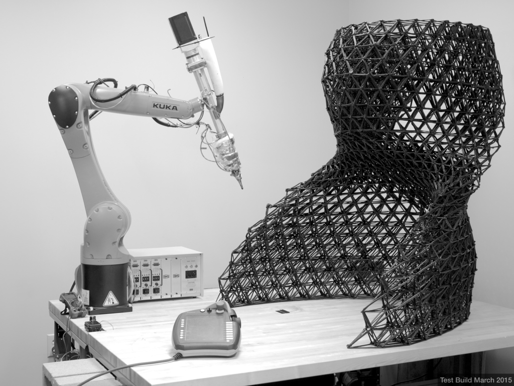
RIGIDING
A typical way to stiffen a mechanical fixture is to leave extra material in places that tend to bend under load. In additive processes, minimizing material consumption reduces spare parts costs. The use of reinforcing ribs and infills provides additional structure without significantly increasing cost or assembly time of the part
Typical milled geometry to minimize material removal and machining time. Typical print geometry to maximize rigidity and minimize material usage
INCREASED MECHANICAL STRENGTH
Using threaded holes in 3D printed plastic parts is an inefficient method of joining fixture parts; these parts are more prone to breakage or wear when reused than metals. Instead, use more resilient assembly methods such as threaded inserts or a pocket to tighten the nut while tightening the bolt. Alternatively, the 3D printed mount can have clearance holes for running bolts up to the T-nuts or mount plate below.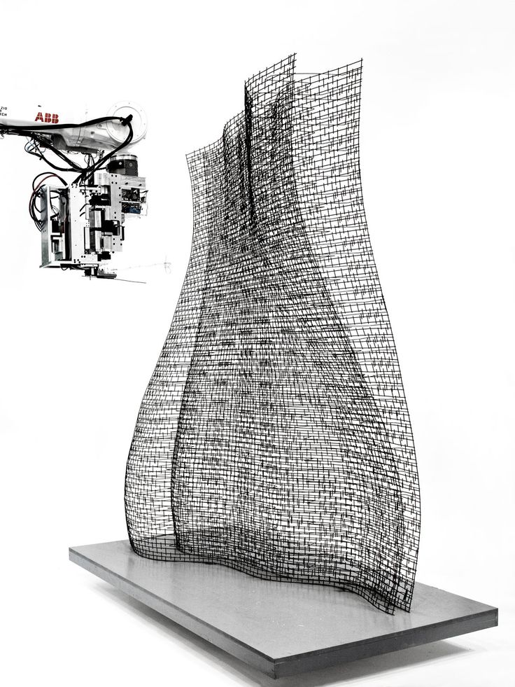 To prevent elastic deformation of the part when screwing onto the work surface, through holes must use clearance tolerances.
PRINTED PARTS EXTENSION
In many cases, 3D printed parts for fixtures and fasteners are augmented using spare parts from industrial plants. This approach works well when some components need the specificity and flexibility of a 3D printed design, but the overall work envelope or other requirements such as stiffness or conductivity cannot be met with an additive process.
Common replacement parts for adding extra functionality to fixtures and fasteners include metal shafts for long distance fastening while maintaining rigidity, or washers to spread screw clamp loads over a large area. Spare parts combined with additive processes quickly add mechanical features such as linear or rotary indexing at a much lower cost than machining.
Drill template slides smoothly over steel rails using Formlabs Durable Resin bushings molded into Tough Resin rail.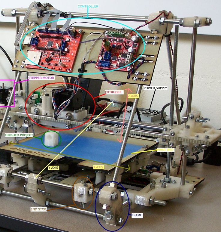
BE AWARE OF FLOW
Some SLA resins experience flow (permanent elastic deformation) if they are constantly loaded, as is the case with printed fixtures fixed to a desktop for extended periods of time. To avoid deformation of parts due to continued loading, it is best to loosen any bolts and remove clamping forces after completing secondary operations.
REPLACEMENT ON REQUEST FOR Worn COMPONENTS
Even under normal conditions of use, fixtures, mounting tools, and fasteners typically break or wear to the point where they are no longer effective.
By creating fixtures and fittings in additive manufacturing, a facility takes control of its own production and is able to change tools on site as needed rather than relying on external suppliers with minimum order quantities. Replacing worn attachments with internal equipment shortens the supply chain and reduces the risk of downtime.
TIP
Some coolants, solvents, and cutting fluids can degrade SLA printing.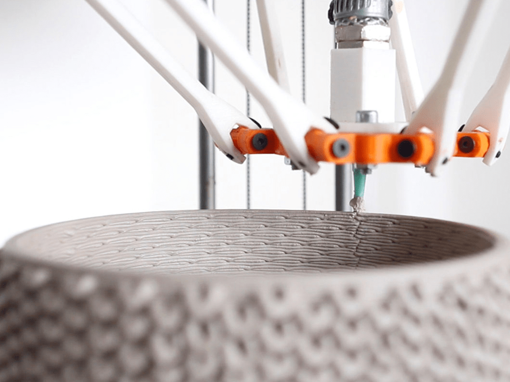 Run a short test to check the overall processing requirements before introducing printed parts into a new application.
Checking a 3D printed part with a dimensional accuracy template.
Print Fixture Test
Once the fixture has finished printing the fixture, clean and allow it to cure per Formlabs material specification. The Form Wash and Form Cure post-processing systems are the best way to ensure that part quality is not compromised by too much solvent or uneven curing.
If Formlabs PreForm software is used to create support structures for the model, remove the supports and carefully sand any remaining depressions to achieve a smooth, flat surface.
TIP
Place a sheet of sandpaper on a known, flat surface and slide the part over the sandpaper, applying enough even pressure to achieve an even finish.
After that, examine the printed part against the original CAD model. Use a gauge or micrometer to check the print dimensions against the dimensions on the drawing or annotated CAD model.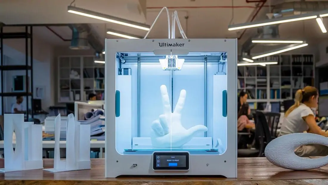 Record any discrepancies that could adversely affect the effectiveness of the mounting or setting tool.
If all dimensions are correct, the next step is to test the functional effectiveness of the fixture.
When loading a part onto the jig, pay particular attention to how well it sits in relation to the mounting surface and supports. A properly designed and built fixture will support the part, eliminating any movement after clamping force is applied.
The clamping force must push the workpiece evenly into the fixture without tilting, shifting or bending the workpiece.
Properly fitted pocket printed with Formlabs Durable Resin.
Component printed with Formlabs Tough Resin that aligns and secures the bonded assembly during cure.
For processes with higher operating forces such as milling or drilling, calculate clamping requirements based on feed and speed, machine power and selected material, and safety considerations.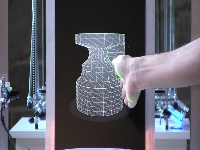 On first use, inspect to ensure intended functionality.
After performing any subsequent operations on the part, an additional check will check the tolerances and also establish an acceptable cycle time. When a new fastener or clamping device is first deployed, more frequent quality checks will reveal any unpredictable operator errors or wear that could lead to a quality error. These errors can be detected at an early stage and corrected either through training or by changing the design of the fixture.
Workflow questions
PARTS REMOVAL
If the fixture truly functions as a time-saving tool, figuring out how to quickly remove parts from the setup is critical, as is loading and securing
To help eject parts, use beveled springs guides or levers to lift the part up from the surface of the fixture
By placing the springs in the fixture, when the clamping force is released, the part will be pulled away from the surface of the fastener, making it easier for the operator to remove the part.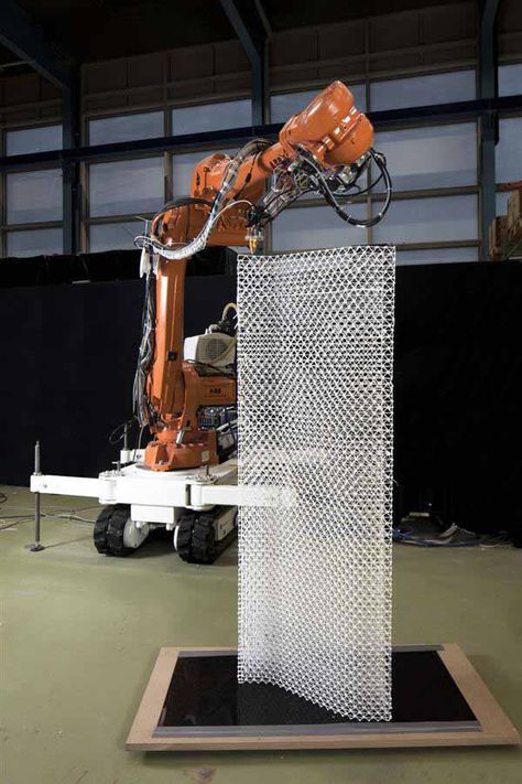 The same can be done with a movable slider or lever, albeit with an additional step required from the operator. Determining the correct approach depends on the application, tool setup, and cycle time requirements.
TOOL USE ISSUES
Any type of machining operation generates garbage. Good fixture design provides tolerances for controlling the impact of such debris. When drilling a hole, for example, small chips are generated. The clearance left in the fixture provides room for chips without affecting the part or tool performance.
Similarly, during milling operations, small pieces of material chips can accumulate on the fixture or fastener. If possible, minimize or eliminate small gaps and pockets where chips can accumulate. Creating deep grooves improves fixture function by allowing chips to fall out of the way of the part when loading and unloading.
Smoothing corners and grooves creates rising surfaces, making it easier to brush, blow or flush debris from the work area. Surface chamfering saves time but is expensive, requiring either the removal of expensive material or part assembly that introduces new seams.
Standard milled and assembled corner positioning device, consisting of three inserts, provides great chip removal capabilities.
Standard geometry 3D-printed angular device for positioning with rounded edges, smooth pockets for discharge and without seams, without increasing the cost of parts
Improving the user's experience in relation to installation and installation devices
Mounting and installation installations and installation installations Mountains fixtures are tools to reduce the required skill level or concentration of the operator, as well as tools to speed up the production of parts.
Properly designed attachments improve worker safety and improve workstation ergonomics for the person who is tasked with the ongoing task of performing a given operation. Successful manufacturing takes into account not only how parts are machined using fixtures, but also how workers mentally and physically perceive the tools they use.
While each application has different requirements, a few general concepts make work easier and improve efficiency:
- Whenever possible, design fixtures for one-handed operation, freeing up the other hand for part positioning, stabilization, and rest during replacement.
- Design fixture to securely hold the part during subsequent unattended operations
- Use geometries that amplify placement errors to make misalignment obvious.
- Consider not only the part in the context of the fixture, but also the overall progress of the job, from loading the part and performing subsequent operations to removing the part and sending it to the next station.
- Always aim for the fewest steps required to use the fixture to minimize cycle time and facilitate worker movement. Simulate these design steps to ensure that all necessary motions and spatial tolerances are included.

Find out how other companies are incorporating 3D printed fixtures and fittings into highly automated lines from the Pankl Racing Systems case study By moving fixture production in-house with 3D printing, Pankl Racing Systems has reduced time and costs without the need to connect the expensive facilities of a CNC production center,
Conclusion
A modern factory must continually fine-tune and implement new technologies to maintain competitive advantage, achieve production and profitability goals, create a safe environment for staff, and reduce worker workload. Additive manufacturing helps achieve these goals by moving the design and production of fixtures and fittings as close to the production site as possible. Engineers who are familiar with the precise context of fixtures and fittings in manufacturing do a much better job of building the right tools in the right way. High-quality, high-precision 3D printers like the Formlabs Form 2 enable even small organizations to bridge the gap between concept and reality to increase productivity and stay competitive.