3D printer bearings
Bearings for 3D Printers - 3DJake International
Sort byRelevanceBestsellersCustomer ReviewsPrice, Low to HighPrice, High to LowNew arrivalsHighest Discount
-
E3D Ball Bearings 5 Model types- With metal cover
- Many uses
-
BROZZL Linear Bearings LM6UU - LM12LUU- High precision
- Long life span
- Easy exchange
-
BROZZL V-Slot Guide Wheel Including Bearings- Outstanding rigidity
- Wear-resistant
- For high loads
-
E3D Linear Ball Bearings (Set of 2)- Good quality
- Good price
- Suitable for linear shafts
-
BondTech Needle Roller Bearings- High precision
- For shaft diameters of 3 mm
- Two bearings per drive wheel required
-
E3D Titan Bearings- Stainless
- Stable and robust
- Good quality
-
Artillery Wheel Bearing- Original spare part
-
Creality Roller with Bearing- Original spare part
- For all CR-10 models
-
BIQU Roller Wheel Bearings- Original spare part
- From BIQU
All prices incl. VAT.
Bearing best STL files for 3D printer・Cults
Cuscinetto lineare LM8LUU 8x15X45
Free
Cuscinetto lineare LM8UU 8x15X25
Free
KIT ATTACCHI PER GUIDE LINEARI SU ARTILLERY X1 E GENIUS
Free
Cuscinetti lineari LM6LUU- LM8LUU- LME10UU- LM12LUU- LM16LUU- LM20LUU- LM25LUU- LM30LUU- LM40LUU- LM50LUU
Free
center finder
Free
TUSH for the Alfawise U20
Free
Printable bushing for lasercut holes
Free
BEARING Turntable
Free
bearing
Free
BASE GIRATORIA RODAMIENTO 608
Free
Ball Bearing 30mm
Free
97_New Frictionless Spool Holder With Metal Shaft
Free
Ninja shuriken keychain spinner NO BEARING gadget
€1. -15% €1.63 92
92
Bearing, gear bearing
€1
16x5x5SandingBlock
Free
Bearing Cleaning Tool
Free
BullDog Thing :)
Free
Manual Swivel Base
€1.19
Ball Bearing (print in place)
Free
BEARING
Free
Printable 608 Ball Bearing
Free
Printable Linear Bearing For 8mm Rods
Free
Colourfabb spoolstand 608 bearing
Free
Ball Bearing
Free
Ball bearing
€1
PluTop Mon — 10+ minutes rotation
Free
BEARING REF - 3/4 INCH
€4. 75
75
BEARING REF - 1 1/4 INCH
€4.75
BEARING REF - 2 INCH
€4.75
BEARING REF - 1 1/2 INCH
€4.75
BEARING REF - 1 INCH
€4.75
bearing Z axis weedo tina2
Free
updated for 5mm ID bearing
Free
Even Cheaper & Lazier Filament Spindle
Free
Prusa i3 MK3 * Y-Axis Bearing Clamp
Free
Prusa i3 MK3 * Y-Axis Polymer Bushings/Bearings
Free
FLSUN V400 SPOOL HOLDER BEARINGS
€1
Mingda D2 filament holder with 608zz bearing
Free
BB King - the 3D Printed Roller Bearing
Free
Side Mountable Filament Spool Holder
Free
FPV Iflight Quad Wrench Sleeve
Free
2020 Spool Holder - Top mount (with or without bearings)
Free
2-speed gearbox
€4. 95
95
Uno Caddy Bearing
Free
Printruder V2
Free
Printable Ball Bearings
Free
outboard motor bearing
Free
Bearing BB6
Free
3D printed bearing design and manufacture
The German manufacturer Franke GmbH designs and manufactures wire cage rolling bearings as a lighter alternative to traditional rolling bearing designs ( fig. 1 ). The history of this product began in 1936, when engineer Erich Franke, while developing an optical device, was looking for a solution to save space and invented a special rolling bearing. A feature of bearings of this type was its non-standard design: instead of ordinary and outer rings, 4 round guides were used ( fig. 2). They formed the basis of the products manufactured by Franke GmbH and are today used in many industries such as
aerospace and medical equipment, as well as for the automation of various processes. Despite the fact that bearings of this design have been thoroughly researched, the specialists of Franke GmbH decided to apply innovative approaches and methods in their design - in particular, topological optimization. This allowed to reduce the weight of the structure.
Fig. Fig. 1. Use of wire cage bearings for telephone and internet communications in aircraft
2. Image of a bearing from the official Franke product catalog
It is worth noting that Franke GmbH has been using 3D printed aluminum housings for several years. The applied additive manufacturing methods allow saving material without losing the strength characteristics of the product.
Wire cage bearings are used in the installation of satellite antennas and are needed for organizing telephone and Internet communications in aircraft ( fig. 1 ). These types of antennas are often located in the rear fuselage and must be turned on during flight, staying in line with the satellites to ensure unhindered data transmission. At the same time, the swivel mechanism itself should be as light as possible.
3D printing and modeling
Franke GmbH engaged two partners, Rosswag Engineering, an additive manufacturing integration and 3D printing company, and CADFEM, to understand the economic impact that can be achieved with modern technologies such as topological optimization and additive manufacturing. GmbH specializing in numerical simulation.
The original bearing provided by Franke GmbH was 25 cm in diameter and contained outer and inner rings. They consisted of two parts, which were made of aluminum, maximally optimized for weight and prepared for CNC machining.
CADFEM GmbH imported the geometry provided by Franke GmbH into a single integrated system for working with the Ansys Workbench design project to use it for preliminary modeling. It allows you to determine how the original bearing works when operating in various modes. The obtained data provided criteria ( fig. 3 ), which experts were later compared to when comparing the original design with the optimized one. After determining all loads and sections without change, topological optimization was started. The Ansys Mechanical solution made it possible to determine insignificant stresses over the entire area of the cage, and the topological optimization tool proposed to completely remove the material in this area ( fig. 4, 5 ).
Fig. Fig. 3. Stress-strain state of the clip
4. Red areas show which material to keep, blue areas to remove
fig. 5. Stage of topological optimization. Remaining material is shown in gray
Fig. 6. Filling the “empty” space with a lattice structure
After that, it was decided to fill the empty space with a lattice structure. Such structures bring additional advantages at a very low weight and maintaining the rigidity of the model ( fig. 6 ). The lattice had minimal dimensions, which made it possible to produce it using 3D printing.
16% weight reduction
Initially, the bearing housing was made in the traditional way and sufficiently optimized. Topological optimization reduced its weight by another 16% using additive manufacturing.
But the simulation itself does not end there. The second important field of application of numerical simulation is the printing process itself ( fig. 7, 8 ). Metal printing uses a significant amount of energy to completely melt the metal powder particles. At the same time, the cooling rate is also quite high. These temperature gradients create strong stresses in the workpiece itself. Supports are required to ensure thermal conductivity during the manufacturing process and to absorb the resulting forces and stresses. Their creation, in turn, increases the printing time and makes subsequent machining a necessary step.
Fig. Fig. 7. The obtained results of modeling the process of 3D printing of the case
8. Simulation of the printing process. Milestones
“We worked on this model with parameters that match exactly the selected material. We've already done calibration tests on projects we've previously done with Rosswag Engineering. Thanks to this data on material properties, we were able to optimize the shape and type of supports, while also taking into account such print parameters as movement speed, laser power and component orientation in space,” comment CADFEM GmbH.
“For the print simulation, the specialists worked closely with Rosswag Engineer-ring,” says Franz Öhlert, designer at Franke GmbH. Each of us shared our experience. We have added additional points for post-processing. Material is specifically added to the product at points where post-processing is needed, such as at the location for installing a bearing.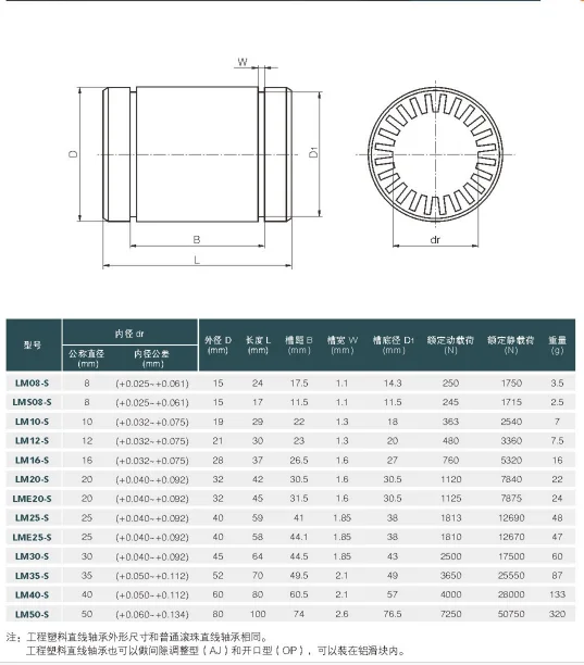 We also determined the location of the supports. The whole model was then brought back into CADFEM to simulate the printing process."
In the final step in Ansys Additive Prep, a custom print solution, the engineers created layout files for the SLM Solutions printer on which all the parts were made ( fig. 9 ). The finished printed bearing housing was delivered to Franke GmbH for further processing, assembly and assembly with wire rings, rolling elements and a cage.
Fig. 9. Rosswag 3D printers.
Image courtesy of Rosswag
Collaboration between real experts (fig. 10)
10. Manufactured case.
Photo: Franke Gmbh
Franke GmbH says: “It was a pilot project. We wanted to know how much savings can be achieved through topological optimization and 3D printing. But it was a very interesting collaboration. We have shown that we can control the printing process with Ansys Additive software. Modeling and optimization are so realistic that the process itself runs smoothly. And the 16% weight reduction of an already optimized component also confirms that topological optimization and 3D printing are taking their rightful place in manufacturing.0007
cycle". ■
Author: Denis Kondratyev, Head of Additic Production, Kadfem SI-Ai-ES
Source Additive Technology Journal No. 3-2021 9000 9000
Tags:
Design and manufacture of a bearing using 3D printing, CADFEM CIS, Franke GmbH, wire cage rolling bearings, 3D printer, additive manufacturing methods, Additive Technologies magazine No. 3 -2021, 3D printing
Diary of a 3D printer. Replacing linear bearings pain, sadness, disappointment and unexpected denouement
Hello everyone! I again return to the modifications of the Anycubic i3 mega 3D printer, which has already acquired a bunch of improvements and, in addition, turned into Anycubic Mega-S. As you know, I try to make the printer as quiet as possible, and got to almost all sources of noise, but it's too early to stop. This time it was the turn of linear bearings. They worked for me for more than a year and are already pretty tired. And so, let's get started.
In fact, the linear bearings of Anycubic 3D printers are a separate story. Although rather not a song, but a source of constant noise, crunch and rattle. Even when new, even out of the box. The owners of this printer model understand what I mean. Well, when the bearings wear out, it's time to change them. So I faced a choice:
- Order exactly the same bearings from China and continue to suffer from noise
- Order nylon bearings from China. They are quieter!
In the end, I decided to try nylon bearings. But as you know, ordering goods from China is a lottery and not only in terms of whether it will reach / not reach, but also in terms of what quality the order will be.
The Anycubic i3 Mega 3D printer uses LM8Luu brand linear bearings.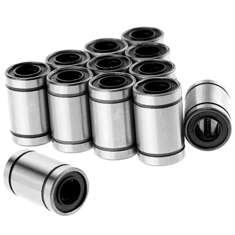 This is not a very common bearing model. So reputable vendors like TriangleLab or Mellow Store don't have these bearings for sale. There are other sellers from whom to buy is a lottery. I finally plucked up the courage to order the LM8LUU nylon counterparts from some obscure vendor. The choice was not great. There are few sellers of such exotics. There are no reviews.
Bearings arrived on time and looked like this:
Outwardly the bearings looked nothing like this. And that's where their dignity ends. On the shaft they sat so-so. A little backlash and gave the impression that they sit exactly only on parole. I am not a great specialist in bearings and I thought, “What if I don’t understand something and in fact I just don’t understand it.” In the end, it was decided to install and test them in action.
And so. Let's start replacing the linear bearings on the Anycubic i3 Mega 3D printer. The instruction is also suitable for the Anycubic Mega-S 3D printer. The main task is to change the bearings on the shafts with minimal disassembly of the 3D printer.
For this operation we will need the following:
Hexagon set or my favorite screwdriver with EMAX hex set
Bearings.
Gasoline “Galosha” or other solvent for removing oil (White spirit, acetone, Isopropanol or alcohol will not work).
Let's start replacing the bearings with the X axis. This is the one on which the printhead hangs.
First, place the printer comfortably on the table and turn it so that it is facing you.
There are special technological holes on the X axis through which you can loosen the screws securing the X axis shafts. See the photo below:
In order not to break anything, we will work with each shaft in turn. Let's start from the top.
Loosen the shaft fixing screws. on both sides:
After loosening the screws, carefully, holding the print head, pull out the shaft. The shaft must be pulled towards the stand on which the extruder motor is fixed, because. there is a special technological hole for mounting the shaft.
The shaft may not be pulled out completely. But I still pulled it out completely, wiped it and degreased it with Galosh gasoline.
Now let's deal with the bearing. It just pops out with a little effort. To do this, the bearing must be shifted parallel to the shaft axis.
Simply put, take it out of the holder and put it aside.
Now insert a nylon sleeve in its place.
We try to place the sleeve strictly in the center.
Now insert the Shaft back and fix it with the locking screws! Important! Clamp without fanaticism, because. you can break the thread.
Now we repeat all the same operations with the lower shaft. We unscrew from one side:
We unscrew from the other side:
We take out the Shaft.
If desired, clean the shaft from the remnants of old grease, dust, dirt, etc.
Change bearing
We insert the Shaft
We clamp the shaft. And that's it. Axis X sorted out.
More adventures await with the Y-axis. Because in the case of all drygosts, this is a table. So you have to change the bearings under the table. Naturally without complete disassembly. I must say right away that the process is a little difficult, but it is perfectly feasible even with my crooked hands :) Let's get started.
To start, release the fastening of the shafts along which the table moves. To do this, unscrew 2 screws on each side on each shaft. Those. Each shaft is fixed with two screws at the front and two screws at the back.
Loose screws? Great, now carefully remove both shafts in turn.
As a result, our table should lie on the cover of the printer electronics unit. It is more convenient to carry out further work with both shafts removed.
Shafts removed.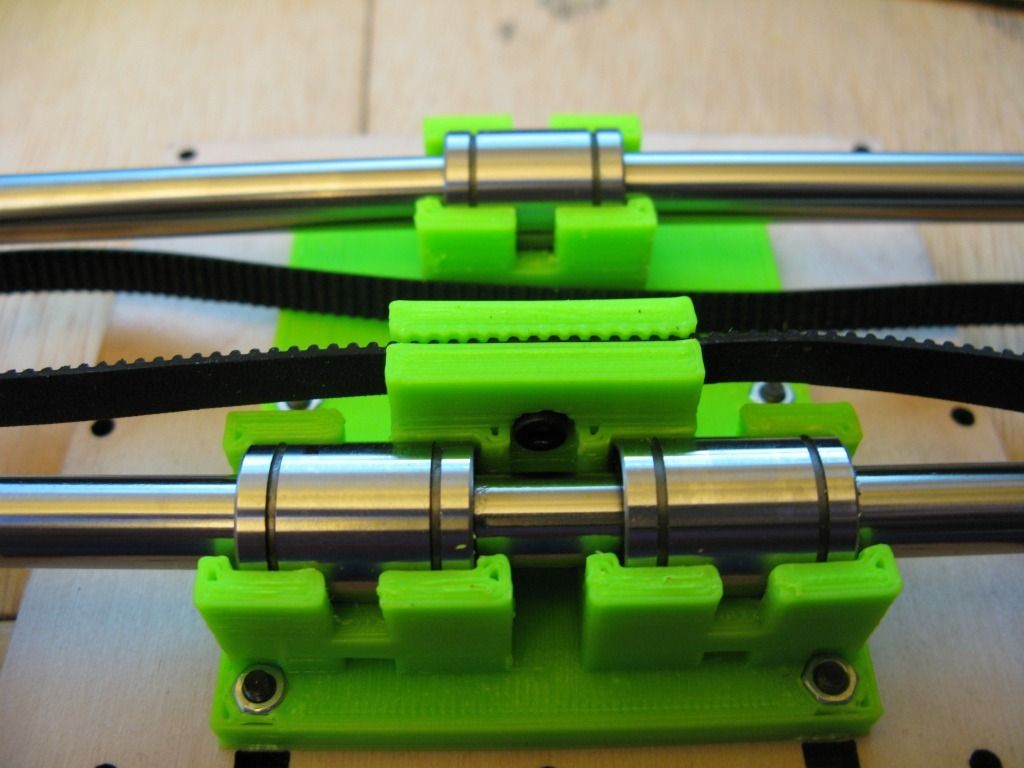 Now they can be cleaned and degreased. Well, we continue.
Carefully remove the old bearings, being careful not to break anything or break the belt. It was convenient for me to do this with a surgical clamp, but you can get by with a long screwdriver, or simply push it out with a shaft.
Pushing out old bearings with new bearings (sleeves) is not a good idea, as it is not comfortable.
Now insert the new bushings in place of the old ones. It should look something like this:
Replaced bearings/bushings. Now put the shafts back.
Now it's time to align the table.
We push it forward as far as possible and carefully clamp the shafts with locking screws.
Once again, I would like to draw your attention to the fact that the shaft mountings are made of soft metal. Overtightening the bolts will cause you to strip the threads and the shaft will not hold, and as a result, the printer will not be able to print.
I remind you of this because I almost broke the thread myself.
After they have been tightened from the front, move the table as far back as possible and clamp the shafts in the mounts at the back.
We check that the table moves evenly and does not bite. If the movements are not smooth, jerky, the clutch bites, you will have to adjust the shafts.
After all operations have been completed, adjust the table. Most likely his settings got lost.
This is how the mini-guide (mini instruction) for replacing the linear bearings on this printer looks like. But that's not all. But only the beginning of the story.
First there was Wow! The printer began to work quietly, almost silently! And then it was ... Well, in general, look at the photo, and think up the selected strong words that I might have uttered.
Due to the fact that the nylon bushings were of poor quality, they began to wedge during operation, as a result, the axle motors began to skip steps.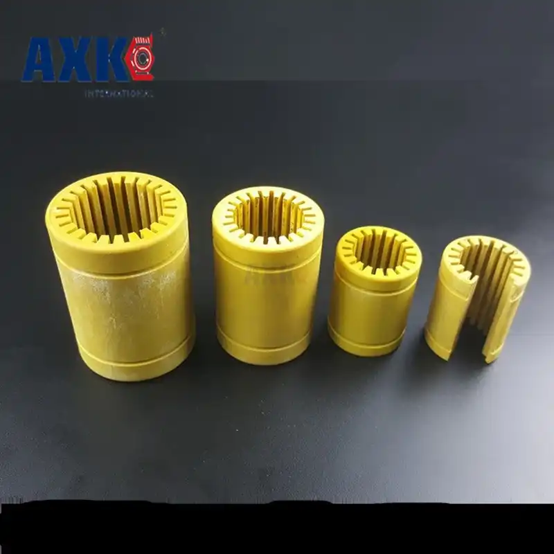 And this naturally leads to displacement of the layers. Well, besides this, ripples appeared on the model.
Nylon bushings do not require lubrication to function properly, but even with lubrication the result is the same. So this is G ... I came across in the open spaces of Chinese trading floors. The bushings were made with large tolerances and anyhow, which led to such sad results.
I have already put native bearings back, but the guys from the Printers3d.by store helped me out. So to say, help came from where they did not expect. They just received plain bearings of the LM8UU format made of POM material. They were offered to me as an alternative to Chinese crafts. Yes, this is not exactly what I need, yes, they are not 45 mm long, but 24 mm, but it's better than nothing. And much cheaper than Japanese LM8UU or nylon from TriangleLab. I don't really have anything to lose. So I agreed, came and took the kit.
I will not repeat the process of installing bushings from the POM. Everything is exactly the same. We unscrew, we change, we collect. Let's take a better look at what happened:
The bearings are obviously too small. At least for this mount. Yes, I understand that the lever is different and the load is different and all that. However, what's done is done. After installing, I moved on to the tests and then a whole bunch of surprises awaited me.
First! I was shocked that the printer began to work silently. From the word at all! The crunch, clanging and other unpleasant sounds disappeared. And taking into account the fact that I have been trying for a long time to make the printer work quietly, the result impressed me. SILENCE! And only a quiet rustle of coolers (a hefty cooler blowing the power supply should be replaced with a silent one).
Second. Print quality has gone up! Small ripples have disappeared on the model. The lines became straight. And all this thanks to the replacement of bushings!
Third! Now you can increase the print speed without losing quality. Now this printer can print at 100 mm/sec without any problems.
So. there is no bad without good. I changed the bushings in December 2019. A month has passed and the printer works like a watch.
What can I finally say?
- If you want to achieve a quiet operation of your 3D printer, change the bearings to bushings. Alternatively, you can consider replacing with bronze bushings.
- Do not get fooled by Chinese parts, especially from unverified sellers. Take goods only from trusted and always with a bunch of reviews.
- Don't be afraid to experiment!
I want to say a huge thank you to the Printers3d.by online store for their help!
If you have not got a 3D printer yet and are thinking about which model to choose, I can recommend the following models:
Anycubic i3 Mega 3D Printer
Anycubic Mega-S (Anycubic S) 3D Printer
Anycubic 4MAX Pro 3D Printer
These are links to trusted vendors that sell original printers.