David 3d scanner calibration
DAVID SLS-1 Structure Light 3D Scanner User Guide
DAVID SLS-1
Getting Started Guide
Version 3.4
3DPE.ir
Specifications
scan object size ~ 10mm – 600mm
now upgraded to DAVID-CAM-3-M 1280 x 960 camera with (double the resolution)
new upgraded megapixel camera lens from Computar
resolution: ~0.1% of object size (down to 0.04mm)
precision: ~0.1% of object size (down to 0.1mm)
scanning time: 2-4 seconds per scan
mesh density: up to 350,000 vertices per scan colour texturing
export formats: obj, stl, ply
| Size of scan object/ surface region s | Calibration pattern | Lens distance b between camera and projector | Distance d between scanner and object | Achievable scan resolution (approx. 0.2% of object size) |
| <30 mm | 30 mm | ca. 30 mm | ca. 90 mm | < 01 mm |
| 50 mm | 60 mm | ca. 40 mm | ca. 120 mm | ca. 0.1 mm |
| 70 mm | 60 mm | ca. 65 mm | ca. 180 mm | ca. 015 mm |
| 90 mm | 120 mm | ca. 80 mm | ca. 220 mm | ca. 0.2 mm |
| 120 mm | 120 mm | ca. 110 mm | ca. 300 mm | ca. 0.25 mm |
| 150 mm | 120 mm | ca. 125 mm | ca. 350 mm | ca. 0.3 mm |
| 200 mm | 240 mm | ca. 160 mm | ca. 450 mm | ca. 0.4 mm |
| 300 mm | 240 mm | ca. 250 mm | ca. 700 mm | ca. 0.6 mm |
| 500 mm | 240 mm | ca. 400 mm | ca. 1200 mm | ca. 1.0 mm |
| in general | similar to object | angle 20°-25° between them | the object should fill the camera image | ca.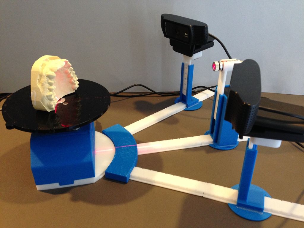 0.2% of object size 0.2% of object size |
Requirements
Standard PC (Windows XP, Vista or 7 – 32 or 64 bit)
Two available USB ports available VGA or HDMI port
Recommended: 2 GHz CPU, 4 GB RAM, 3d graphics card (e.g.
NVIDIA GeForce or ATI Radeon
DAVID SIS-1
Contents of Package
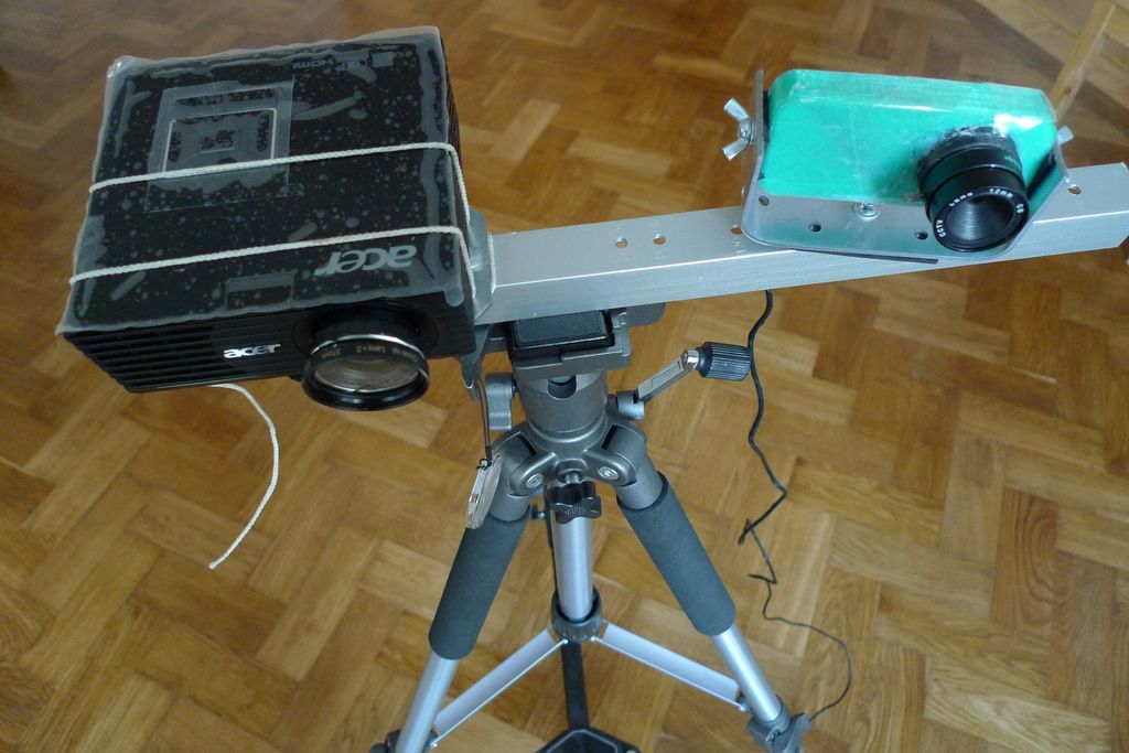
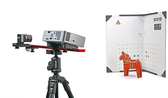
- SL Scanner pre-mounted, consisting of
- Video projector
- Camera with focusable lens
- Mounting rack with ball joint (for the camera)
- Tripod with protective bag
- 2 calibration panels with 2 mounting tracks at 90°
- USB drive with DAVID-Laserscanner Pro Edition and camera drivers
- Accessories for projector
- External wall power supply
- Remote control
- VGA cable
- HDMI cable
- 2 AV cables (not required for scanner)
- Protective bag
- User Manual
- Adapter set for global power supply
- USB cable for camera
- Cable straps
System Requirements
- Windows XP, Vista, or 7 (32-bit or 64-bit)
- 3D graphics adapter
- Available VGA or HDMI port
- Two available USB ports
- Recommended: Dual-core processor, 2 GHz, 4 GB RAM, NVIDIA or AMD graphics adapter
Safety Instructions
- Only operate the scanner in a dry environment.
- Do not operate the scanner in areas where there is a risk of explosion.
- Repairs to the scanner or its components may only be performed by an authorized service center or the DAVID-Laserscanner after-sales service.
- Do not make changes of any kind to your scanner.
Preparation
Setup
Before connecting the devices, adapt the whole scanner setup to the size of the object or surface region you want to scan.
The intersection angle between projection and camera view should be around 20°-25° (max. 15°-35°).
The following table should give you some indications for an optimal setup
| Size of scan object/ surface region s | Calibration pattern | Lens distance b between camera and projector | Distanced between scanner and object | Achievable scan resolution (approx.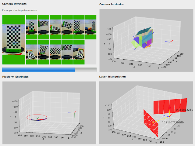 0.2% of object size) |
| <30 mm | 30 mm | ca. 30 mm | ca. 90 mm | < 01 mm |
| 50 mm | 60 mm | ca. 40 mm | ca. 120 mm | ca. 0.1 mm |
| 70 mm | 60 mm | ca. 65 mm | ca. 180 mm | ca. 015 mm |
| 90 mm | 120 mm | ca. 80 mm | ca. 220 mm | ca. 0.2 mm |
| 120 mm | 120 mm | ca. 110 mm | ca. 300 mm | ca. 0.25 mm |
| 150 mm | 120 mm | ca. 125 mm | ca. 350 mm | ca. 0.3 mm |
| 200 mm | 240 mm | ca. 160 mm | ca. 450 mm | ca. 0.4 mm |
| 300 mm | 240 mm | ca. 250 mm | ca. 700 mm | ca. 0.6 mm |
| 500 mm | 240 mm | ca. 400 mm | ca. 1200 mm | ca. 1.0 mm |
| in general | similar to object | angle 20°-25° between them | the object should fill the camera image | ca. 0.2% of object size 0.2% of object size |
The camera can be mounted left or right of the projector – depending on how a suitable distance between their lenses can be achieved. The DAVID software also supports a vertical setup, with a camera and projector above each other.
Installation
Connect all components as depicted below:
Installation of the Camera Drivers
- Plug the USB drive into your PC, then choose “Open” resp. “Explorer”.
- Launch “Install_DAVID-CCD-Camera_Driver“ (may require administrator rights).
- Follow the instructions on the screen.
Projector Settings
The projector is shipped with optimal settings. We recommend not to change anything in the projector’s on-screen menu.
You can restore the recommended settings in the projector’s on-screen menu at any time:
- Select “Reset“
- Be sure to switch “Auto Keystone“ OFF, and set the manual Keystone value to 0.
For more information, please refer to the projector’s User Manual.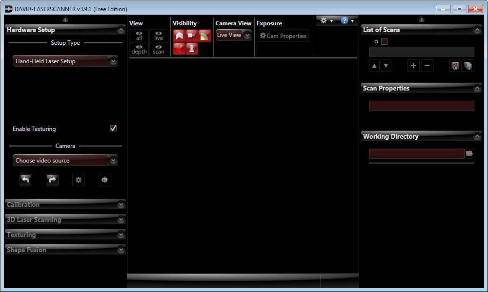
Setup Projector as Extended Desktop in Windows
With your right mouse button, click on a free space on your Windows desktop. Choose “Resolution” or “Properties” (depending on your Windows version).
In this dialogue window, you can separately change the settings of your two displays, the monitor and projector.
Your monitor should be set as “main display”. Set the projector to be an extended desktop (“extend these displays” / “extend the desktop to this display”).
This setting is required so that DAVID can project its scan patterns and show the user interface on your computer screen at the same time. You can find more detailed instructions in our online user manual at http://www.david-laserscanner.com/, “Manual”, in chapter “3D Structured Light Scanning“.
When these settings are correct, your monitor and projector will show different contents (but with the same desktop wallpaper). You can move the mouse pointer sideways from the monitor into the projected image.
The Windows Taskbar and most desktop icons will be shown only on the monitor. All windows can be moved from monitor to projector, and vice versa.
If the DAVID main window is shown on your projector, grab its title bar with the mouse and move it over to your monitor.
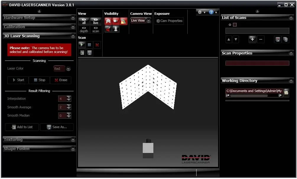
Scanning with DAVID
Launch DAVID by starting “Start_DAVID3“ on your DAVID USB key.
On the left side, you can see the expandable main menus. Each menu is dedicated to one of the following work steps, which you will usually walk through from top to bottom.
For the individual work steps, different camera and/or projector settings may be optimal. For example, Camera Calibration may require a different Exposure Time or Texturing may require a darker projector setting. The respective controls are available at all times, and DAVID will remember and restore the settings separately for each work step – depending on which menu is currently expanded.
Our software is developed and improved continuously.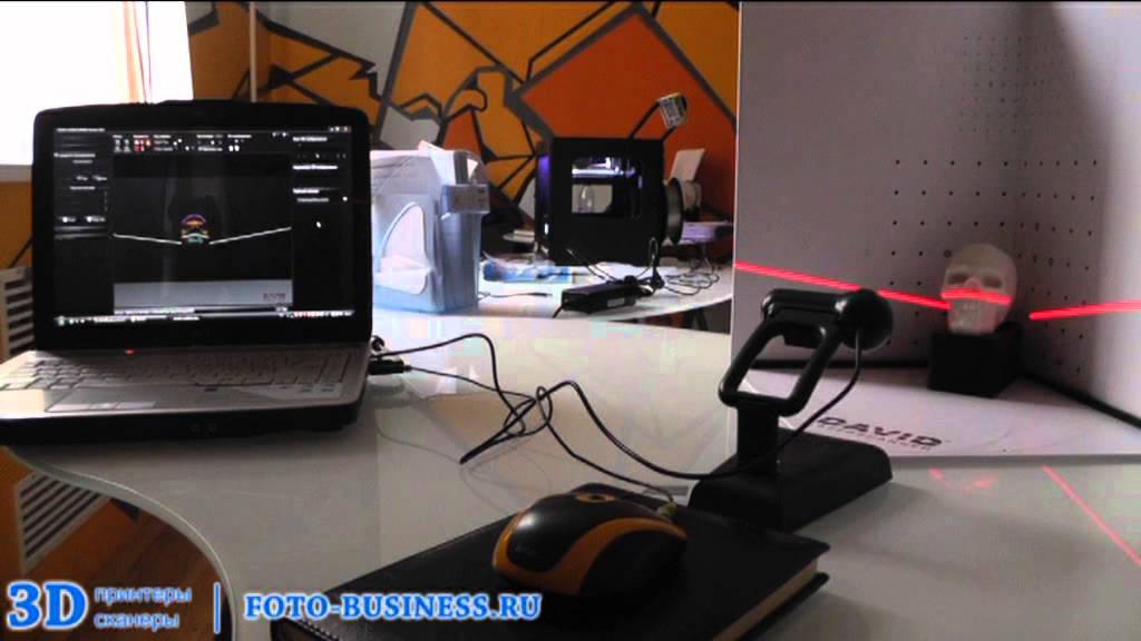 Therefore, please use the automatic update. All updates within version 3. x are free of charge.
This printed manual refers to version 3.4 of the software and may already be out of date. Please also read our detailed and always up-to-date online manual, which you can find on http://www.david-laserscanner.com/.
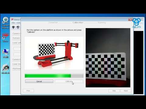
Calibration of the Scanner
One advantage of the SLS-1’s modular setup is that its size can be adjusted to very different object sizes.
Therefore, calibration (measurement of the current hardware setup in the DAVID software) is required, allowing the software to obtain undistorted 3D data at the correct scale. We use a calibration corner as a reference, whose properties are known precisely.
The three steps, hardware setup, camera calibration, and projector calibration, must be carried out in the following order.
Menu “ Hardware Setup “: Adjustment and settings of projector and camera
- Select setup type “Structured Light Setup“.
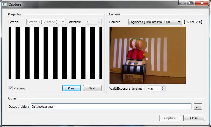
- Choose the correct “Screen ID“ such that the stripe pattern is projected by the projector.
- Place the scanner in front of the scanned object and adjust the projector’s position and direction so that its projection illuminates the scanned surface – not less, but also not much more.
- Use the projector’s focus ring to adjust sharpness, such that the black and white stripes are well focused on the object’s surface.
- Below “Camera”, select your camera (DAVID-CAM-2-M). You will see the live view. If necessary, roughly adjust the camera’s mechanic aperture and focus ring.
- Aim the camera so that it can see the projected pattern on the object. Then fix the ball joint.
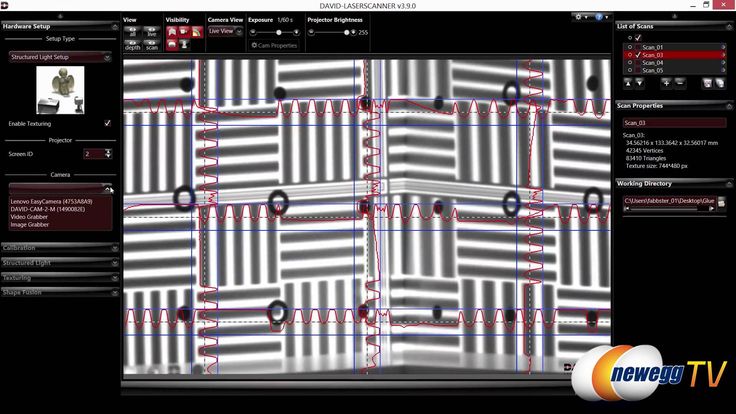
- The Exposure Time should be set to 1/60s, otherwise, the camera image might flicker or pulse when looking at the projection.8. Adjust the mechanic aperture at the camera’s lens. Regard only those image regions that show the circular wave pattern: The red intensity curves must be sinusoidal and must not be over-or undersaturated.
In other words, the red sine curve must not be cut off at the blue borders.Too dark.
→ Increase aperture sizePerfectly adjusted, the sine wave nearly reaches the blue borders. Too bright,
The sine wave is cut off (overdriven).
→ Decrease aperture sizeThe Projector Brightness control should be at a maximum in most cases. Only reduce it if a clean, undistorted sine wave cannot be obtained otherwise.
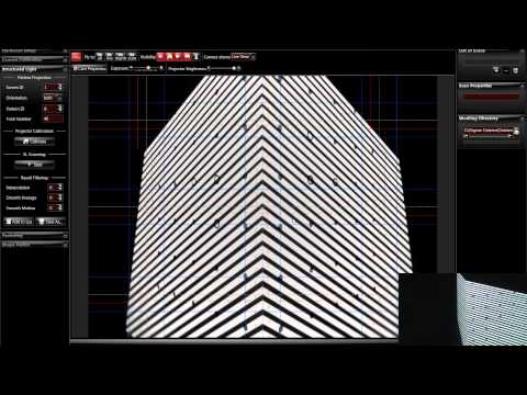
- Look at the projected grey planes in the camera image. Adjust camera focus (mechanic focus ring) so that the object is depicted as sharp as possible. Also, you can use the projected black and white stripes for focussing.
- Fasten all screws (projector, ball joint of camera) so that nothing can be dislocated from now on.
Menu “ Camera Calibration“
- Select a calibration pattern size that fits the object (see table on page 3).
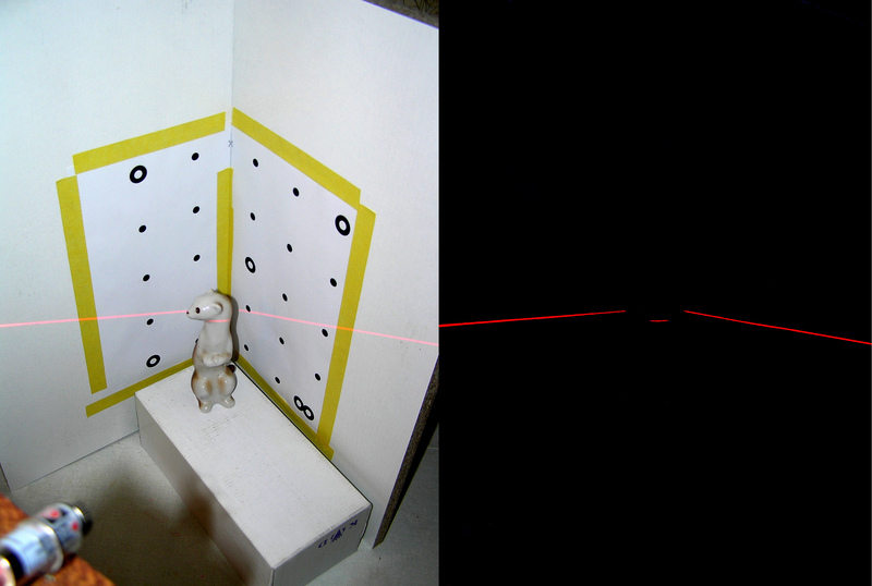
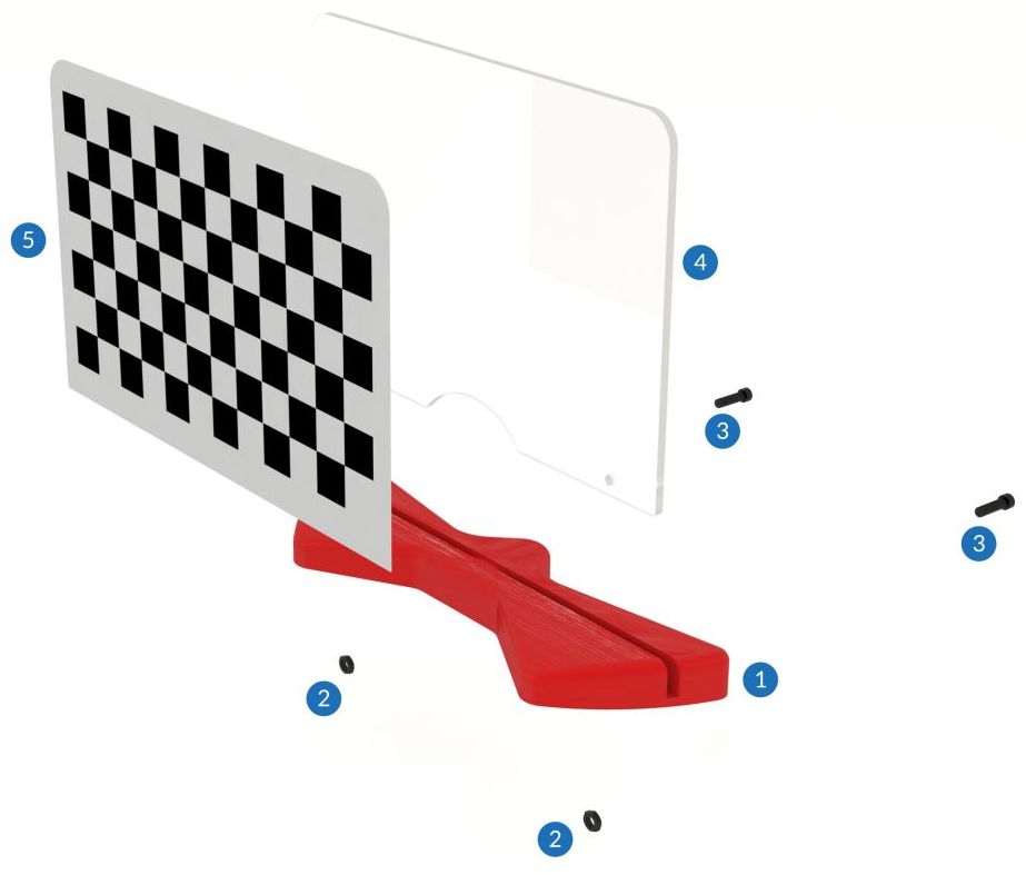 Set up the calibration corner at precisely 90°, using the mounting tracks. For starters, the pattern should be flipped to the inside, while advanced users may be able to reduce reflections with a concave corner setup.
 - Remove the object and set up the scanner and the calibration corner in front of each other, with approx. the same distance as the object before. The projection and camera image should be well focused.
The camera image must show at least the 6 ring markers and a few dot markers. The whole camera image should be filled with around 15 to 70 calibration markers, and the camera should not able to look past the calibration boards.
You can move, rotate and tilt the scanner as a whole, but you should not change anything above the red mounting rack. - enter the scale size of the calibration pattern at “Calibr. Scale”. You can find the number printed on the panels right next to the respective pattern.
- The projector now shows a plain white or grey face.
 You can adjust its brightness with the ProjectorBrightness control so that the calibration markers are clearly visible in the camera image. If there is enough environmental light in the room, you can set the control to 0.
If necessary, you can adjust the camera Exposure too. - Click “Calibrate“ in order to calibrate the camera.
In this step, the software computes the position and orientation of the camera, as well as the focal length and distortion parameters of its lens. - From this moment on, do not move or adjust anything at the scanner – otherwise, you will have to repeat the calibration.
Menu “ Structured Light Scanning “: Calibration of the projector
- When you open the Structured Light Scanning menu, the projector will again show the setup pattern, and both projector and camera will be set back to the settings you have made in step 1.
- Select a profile (recommended: “default“).
- Check the camera image again.
 In those areas that show the circular wave pattern, the red intensity curves must not be cut off at the blue borders. Carefully adjust the lens aperture if necessary, but be sure not to change the focus.
 - Click “Calibrate” in order to calibrate the projector.
In this step, the software measures the position and orientation of the projector, its focal length and distortion coefficients, as well as optical transmission properties and delays of the whole system.
Your scanner is now calibrated. This refers to the position and orientation of the camera and projector relative to each other, and the focus and brightness settings. You may move, rotate and tilt the scanner as a whole, and you can close and restart the DAVID software, without losing the calibration.
However, if you rotate the camera or projector with respect to each other or change the focus (e.g. in order to scan much smaller or larger objects), you will have to repeat the whole calibration procedure.
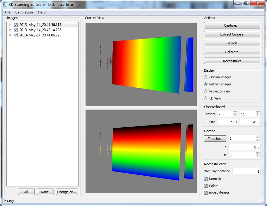
3D Scanning
Menu “ Structured Light Scanning“
- Place the scanner and object in front of each other, as you did during calibration.
If the distance is too different, the projected stripes and camera image will be out of focus. In this case, correct the distance, not the focus rings.
Important: For each scan, observe that the red sine waves are not cut off / overdriven (this refers only to the image regions where the circular wave pattern is visible). Should a correction be required, carefully adjust the camera aperture, but do not change the focus. - Each click on “Start” performs a new scan.
DAVID projects a set of different stripe patterns and records the images. This takes 2-4 seconds, depending on the settings.
- If you check the “Auto. grab texture” option, DAVID will record a texture with each scan. If the texture is too bright or too dark, you can adjust the texture settings in the Texturing menu (see below).
- With your mouse, you can rotate, move and zoom through the 3D view.
- The scans need to overlap sufficiently so that they can be combined/aligned later on. Generally, 6-8 scans of different views around an object are required, plus possibly a few of the top and bottom sides. Grabbing a texture with each scan can help with the automatic or manual alignment.
- Save each successful scan as an OBJ file (“Save As“) and/or add it to the List of Scans.
After each click on “Add to list”, you can immediately align the new scan to the previous ones (Shapefusion menu, see next chapter). Alternatively, you can first collect more scans in the Structured Light menu, and align them all later.
report this ad
Menu “Texturing”
You can record a texture with each scan. It is colored if you are using a color camera, otherwise, it is greyscaled.
The texture usually requires different illumination settings. When the Texturing menu is open, you can adjust Projector Brightness, camera Exposure, or other camera properties as you like, without influencing the scan settings.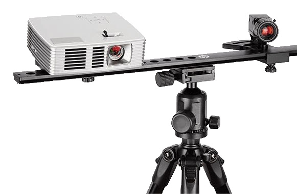 A decent texture is like a good photo: uniform illumination, not too bright, not too dark. It may be helpful not to use the projector as a light source (set Projector Brightness to 0), but instead use diffuse environment light in the room.
- The button “Grab Texture” records new textures and applies them to the scan at hand.
- All settings here are stored separately. For the following scans, you will not have to open the Texturing menu each time. Instead, you can use the “Auto. grab texture” option in the Structured Light menu.
Alignment and Fusion of Multiple Scans
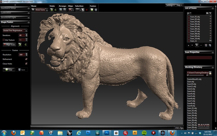
Menu “Shape Fusion“
This menu offers to 1. align several scans to each other and 2. fuse them to one closed 360° model. You can export the fused object in various file formats and use it e.g. for 3D printing. In the following, we describe the general case of aligning scans from arbitrary perspectives. Hints about special cases and more detailed information can be found in the online manual on www. david-laserscanner.com.
- Scan Alignment
• Single scans are usually collected in the List of Scans, using the “Add to List” button during scanning.
You can also import scans from OBJ files by drag-and-drop or with the “+” button below the list.
• Hint: Each scan can be toggled visible/invisible with the button.
• Hint: If necessary, you can clean your scan with the Selection Tool. At this time you should only remove surface areas that are not useful for alignment, i.e. which no pair of scans have in common.
• Hint: With the Arrange buttons you can arrange all scans next to each other in order to get a good overview.• DAVID offers several alignment modes. In general, you should start with the “Free” mode, which aligns one scan to one other with each step. In order for the automatic mode to find the correct alignment, the scans have to overlap sufficiently, i.e. contain a good portion of identical areas.
The button starts the alignment mode. In the 3D view, first, click on the scan you want to align, “Scan A”. Then click on the scan you want to align it to, “Scan B”. These images show an alignment of the blue scan to the green one: Subsequently, align more scans to those previously aligned. Always select pairs that overlap as much as possible. In the example shown above, a good next step would be to align the yellow scan to the blue one, and so on.
• After all scans have been aligned, you should run the „Global Fine Registration“ mode.• Hint: All scan movements can be undone separately with the “Undo” button .
• Hint: You can save your single scans at any time. They will be saved in their current position and rotation in space, so you won’t have to align them again.
• Hint: After some alignment steps it can be helpful to “combine” several scans temporarily. Select two or more scans in the List of Scans (press and hold the Ctrl key while you click). Then click on them with the right mouse button, and choose “Combine”.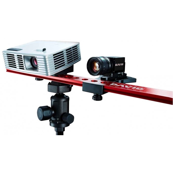 This puts the selected scans into one group temporarily and allows you to tread them all as one. In our example, the Büssing bust, we might combine scans 1 and 4 (or all scans 1-4) and then align scan 5 to that group. This way scan 5 would be aligned to all scans, which includes more overlapping areas and thus can lead to a more precise alignment.
Right-click on the group’s name in the list and choose “Uncombine” to separate the group again.
• If automatic alignment cannot solve an alignment task correctly, you can align scans manually by mouse, keeping the Ctrl key pressed. Please refer to the online manual for details. - Scan Fusion
• Only visible scans will be fused, so select all scans with the button.
• Click “Fuse” to start the Fusion. This is a complex process that requires a computation time of several seconds or minutes. All visible scans will be merged into one closed triangle mesh, removing small artifacts. If the scans have textures, a fused texture will also be created. Optionally, all holes will be closed.• Finally you can use the “Save” button to export your fused 3D model as OBJ, STL or PLY file.
Terms of Warranty
This device was manufactured using the latest production methods and has been carefully inspected. All DAVID Laserscanner® products are subjected to rigorous quality control. If this device nevertheless fails to perform faultlessly, this is something we regret and we ask you to consult your supplier.
The following conditions apply to warranty claims:
This warranty is valid for a period of 24 months from the day of purchase. Please keep the receipt carefully as proof of purchase when making a warranty claim.
The defective product may be returned to your supplier during the warranty period. If the warranty claim is valid you will be entitled to the repair of your device or a new device will be given to you. This is free of charge. Alternatively, a warranty claim can be settled through reimbursement of the purchase price.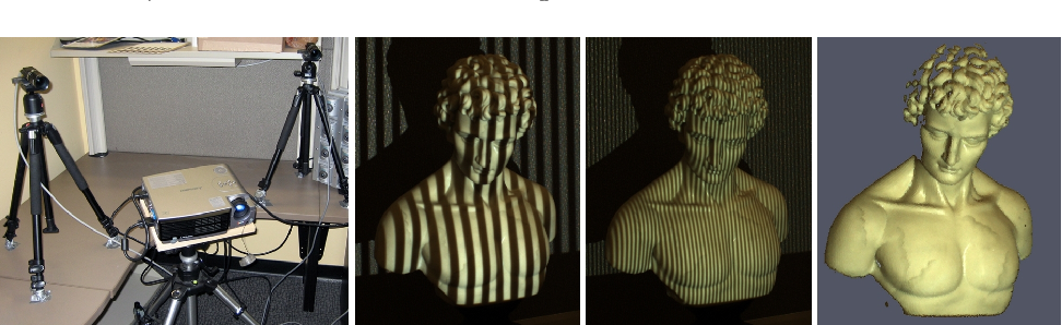 After the warranty period has expired you still have the option of sending the defective device to your supplier or to the DAVID Laserscanner®’s after-sales service for repair. Repairs made after the expiry of the warranty will be subject to a charge. Your statutory rights are not affected through this warranty.
Damage caused through improper handling, use, storage, changes to the electronics, lens, or housing, or through Acts of God or other external influences or any operation outside of the technical specifications is not covered by this warranty.
Before returning the device please contact your supplier to ensure your warranty claim is processed as efficiently as possible. If it is not possible to process your warranty claim through your supplier, you may as an exceptional case contact the DAVID Laserscanner® after-sales service directly.
Disposal / Recycling
Waste batteries or accumulators may not be disposed of as household waste. Every consumer has a statutory obligation to properly dispose of these items at officially designated points of disposal. Never discard electronic components of the DAVID
Laserscanner in standard household waste. In accordance with the EU Directive 2002/96/EC on waste electrical and electronic equipment, this must be disposed of in accordance with local regulations. You can dispose of the product at your local public point for the collection of electronic waste.
DAVID Vision Systems GmbH
Rudolf-Diesel-Str. 2a
D-56070 Koblenz
Germany
Phone: +49(0)261 983 497-70
Fax: +49(0)261 983 497-77
Mail: [email protected]
Web: www.david-laserscanner.com
© 2012 DAVID Vision Systems GmbH
Documents / Resources
| DAVID SLS-1 Structure Light 3D Scanner [pdf] User Guide SLS-1, Structure Light 3D Scanner |
Buy DAVID 3D Calibration Panels Set Online at desertcart INDIA
Brand : David Vision Systems
Brand : David Vision Systems
Description
- Precisely manufactured cardboard panels (300*420mm) with calibration patterns in different sizes.
- Base plate (300*300mm) with aluminium rails.
- Imported from USA (Sizes & Specifications are based on the USA Market).
This package contains precisely manufactured cardboard panels (300*420mm) with calibration patterns in different sizes. These panels are designed to complement DAVID 3D scanning software, which is available to purchase separately. The base plate (300*300mm) with aluminium rails allows for a convenient and stable setup of the panels in a precise 90° angle. Base plate and panels consist of 3mm thick PVC. The four calibration panels have grid sizes of 30mm, 60mm, 120mm, and 240mm, respectively. They are suitable for scanning objects of sizes between approx 50mm and approx 300mm. Note: Enter the respective grid size into the DAVID software before calibrating the camera.
Show More
Reviews
Disclaimer: The price shown above includes all applicable taxes and fees. The information provided above is for reference purposes only. Products may go out of stock and delivery estimates may change at any time. desertcart does not validate any claims made in the product descriptions above. For additional information, please contact the manufacturer or desertcart customer service. While desertcart makes reasonable efforts to only show products available in your country, some items may be cancelled if they are prohibited for import in India. For more details, please visit our Support Page.
Frequently Asked Questions About DAVID 3 D Calibration Panels Set in India
Where can I buy DAVID 3 D Calibration Panels Set online at the best price in the India?
desertcart is the best online shopping platform where you can buy DAVID 3 D Calibration Panels Set from renowned brand(s). desertcart delivers the most unique and largest selection of products from across the world especially from the US, UK and India at best prices and the fastest delivery time.
Is DAVID 3 D Calibration Panels Set available and ready for delivery in in India?
desertcart ships the DAVID 3 D Calibration Panels Set to and more cities in India.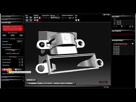 Get unlimited free shipping in 164+ countries with desertcart Plus membership. We can deliver the DAVID 3 D Calibration Panels Set speedily without the hassle of shipping, customs or duties.
Is it safe to buy DAVID 3 D Calibration Panels Set on desertcart?
Yes, it is absolutely safe to buy DAVID 3 D Calibration Panels Set from desertcart, which is a 100% legitimate site operating in 164 countries. Since 2014, desertcart has been delivering a wide range of products to customers and fulfilling their desires. You will find several positive reviews by desertcart customers on portals like Trustpilot, etc. The website uses an HTTPS system to safeguard all customers and protect financial details and transactions done online. The company uses the latest upgraded technologies and software systems to ensure a fair and safe shopping experience for all customers. Your details are highly secure and guarded by the company using encryption and other latest softwares and technologies.
Range Vision Spectrum
Range Vision Spectrum You have disabled JavaScript. It scares.Partners
-
Scanner for consistently high resolution and accuracy
-
Best price for semi-professional solution
-
No analogues on the Russian market
-
Universal 3D Scanner - for miniature parts, medium and large objects
-
Our bestseller in the Russian Federation and in the world market
One scanner - a range of options
Choose and customize scanner options for your application
Sign up for a free online demo!
Get a unique opportunity to test the RangeVision Spectrum 3D scanner online before choosing. Convince yourself of its capabilities!
Versatile with stable scanning accuracy
Three scanning modes
For convenient work with different types of objects
Choose the right mode for your tasks
-
Scanning on a turntable
Quickly and easily scan an object mounted on a turntable platform with the push of a button.
 When the object is rotated, the fragments of the model are aligned automatically.
 -
Scanning with markers
Automatic alignment of model fragments by markers applied to the surface of the object. Used to improve scanning accuracy. External photogrammetry systems are supported.
-
Basic Scan
Used to scan objects that cannot be digitized in other ways, such as museum exhibits. The fragments of the model obtained from different angles are combined according to the features of the object surface geometry.
Scanning objects from 1 cm to 3 m
- Small size
- The average size
- Big size
Applications
Recommended for educational programs and institutions
Order Spectrum Educational
Spectrum scanner that is easy to use
10 questions before buying a 3D scanner
3D model examples
-
Automotive manifold View on site
-
lighter View on site
-
Dragon View on site
-
Lion figurine View on site
-
Pedal View on site
-
Sculpture of a deer View on site
-
Skull ring View on site
-
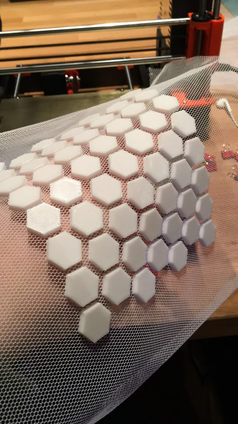
Tiled View on site
-
badge View on site
-
Inkwell View on site
-
Bas-relief View on site
-
Bust View on site
-
Helmet View on site
-
Turtle figurine View on site
-
Wooden baluster View on site
-
Collectible figurine View on site
-
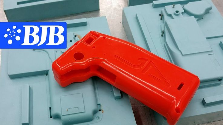
Glue gun body View on site
Specifications
| Scan Technology | structured illumination | ||
| Projector resolution | 1280 x 800 | ||
| Scan area, mm | 540x400x400 | 320x220x220 | 135x100x100 |
| Working distance, m | 0. | 0.56 | 0.26 |
| Error, µm | 120 | 60 | 40 |
| 3D resolution, mm | 0.25 | 0.15 | 0.06 |
| Ability to capture texture | there is | ||
| Camera resolution | 3.1 MP | ||
| Model stitching | by markers, by geometry | ||
| Received formats | OBJ, PLY, STL, PTX, ASCII | ||
| Scanner Power | 100-230V | ||
| Minimum PC Requirements | Intel Core i5 6500 or better, 8 GB RAM | ||
| Connection interface | HDMI, 2 x USB 2. USB 2.0 for desk | ||
| Supported OS | Windows 8.1/10/11 64bit | ||
| Rotary table | there is | ||
| Table platform diameter | 20 cm | ||
| Maximum table load | 20 kg | ||
| Table food | 220V - 12V/1A | ||
| Dimensions of the scanner in the case | 530x430x200 | ||
| Scanner weight | 1.65 kg | ||
| Weight of the scanner in the case | 8.5 kg | ||
| Certificates | EAC, CE | ||
| Guarantee | 1 year | ||
 96
96 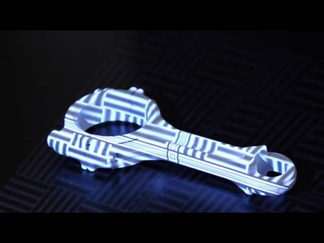 0
0 Note: Product appearance may differ from website photos.
We are trusted
User Testimonials
David Wohanka
EngineerAfter reviewing the various offerings on the market for reverse engineering and prototyping, we chose Spectrum. We really liked the ability to work with markers and changeable scan zones. We can use Spectrum to scan various objects, including those with complex geometry. Perhaps we can agree that the Spectrum is three scanners in one.
Lukasz Mlynar
Project Manager We specialize in creating visualizations. The Spectrum was perfect for these purposes: the resolution, the accuracy, the ability to scan in color - all perfectly matched our needs. And the equipment made it possible to use it both in the office and on field work (we often cooperate with museums and it is much easier to scan on their territory than to transport exhibits to our office). We really liked that the scanner comes with everything you need to work in different modes - it saved our budget a lot.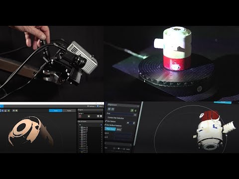
Where to buy
To purchase a 3D scanner, contact a distributor in your city!
Articles and reviews
Creating a Brain Cutting Template Using a 3D Scanner and a 3D Printer
UMATEX Rosatom uses RangeVision 3D scanner to create a sports body kit for Kawasaki Puccetti Racing motorcycle
How to Solve Shelby Cobra Body Geometry Problems with RangeVision Spectrum 3D Scanner
RangeVision Spectrum:
Temperature Compensation AlgorithmRangeVision Spectrum 3D Scanner:
promo video
Any questions?
↑Thank you for your question!
Our manager will contact you shortly
Thank you for your application!
Our manager will contact you shortly
This site uses cookies. By clicking ACCEPT or by continuing to browse the site, you consent to their use. More.
Scanner Calibration and Correction - Artec Studio Documentation 11
The Diagnostic Tool is a special utility used to calibrate Artec scanners and to correct an existing calibration. Calibration in the broad sense of the word is the process of checking and adjusting the measurements made by the scanner by comparing them with reference values. Each Artec scanner comes pre-calibrated.
In some cases, due to careless handling or transportation (shaking, accidental drops, some other reasons), the scanner may no longer capture 3D surfaces properly. In this case, the scanned surfaces may be reconstructed only partially, holes may appear (in Fig. 153, the results of poor reconstruction are visible on the blue surface). These problems can be solved with correction or calibration.
Depending on the scanner model used, the Diagnostic Tool can work in one of three operating modes:
-
Correction for Artec MHT, Artec MH, Artec L and Artec EVA
scanners -
Correction for Artec Spider
scanner -
Artec Spider
scanner calibration
Note
Calibration is only available for Artec Spider scanners.
Usage Guide
Correction differs from calibration in that it retains the current calibration, changing only the correction factor to improve the reconstruction. The accuracy of geometry and linear measurements is not guaranteed when correction is applied.
| Mode | Features | Speed | For Spider? | For EVA, L, MHT? |
|---|---|---|---|---|
| Correction | Inaccurate | Quick | Yes | Yes |
| Calibration | Fine [1] | Requires preparation | Yes | No |
| [1] | Returns the original values given in the device specification. |
Starting the Diagnostic Tool
Before starting the Diagnostic Tool, make sure that the scanner you want to diagnose is displayed in the Artec Installation Center in status Leased or Activated . You can run the application either from the Start menu by selecting Start ‣ All Programs ‣ Artec Group ‣ Artec Studio ‣ Diagnostic Tool, or from Artec Studio by selecting Run Diagnostic Tool from the File menu.
If multiple scanners are connected, select the desired scanner from the drop-down list.
Fig. 149 Diagnostic Tool window
The window of the utility in question is divided into three zones: window 3D view , right panel and toolbar (see Fig. 149).
Scanner correction
Calibration data correction for EVA, MHT, MH and L scanners
For Artec EVA, Artec MHT, Artec MH and Artec L scanners, only correction of the current calibration settings is available.
Fig. 150 Artec EVA
Scanner Adjustment Results-
Run the Diagnostic Tool as described in Starting the Diagnostic Tool.
-
Select the scanner you want to diagnose.
-
Click the Start Diagnosis button or the button, the scanner will start the preview mode, and the range finder will appear in the 3D view window and the right panel will open with the 2D camera preview window.
-
Point the scanner at a right angle at a flat, light (but not shiny) plain surface, such as a wall or floor, from a distance of 650–700 mm for Artec MHT, Artec MH, Artec EVA scanners and 850–900 mm for Artec L scanners. The surface will start to display in window 3D view in blue.
Note
If the displayed surface is not flat and has holes, it is worth performing a correction.
-
Press the Start Correction button or the button on the scanner body. In addition to the blue surface, a yellow surface will appear in the 3D view window .
 Blue corresponds to the surface taken with the original calibration data, and yellow corresponds to the corrected data.
 -
Two indicators in the right panel help you evaluate the quality of the surface (green for good correction, yellow for fair, and red for bad). If the corrected (yellow) surface has no holes, is fairly flat, and the correction results are what you expect, click the Apply button or the button on the scanner. Otherwise, press the Cancel button or the button on the scanner.
Spider calibration correction
Artec Spider correction is slightly different from Artec MHT and Artec EVA.
Fig. 151 Correction process Artec Spider
-
Run the Diagnostic Tool as described in Starting the Diagnostic Tool.
-
Select Artec Spider from the dropdown list.
-
Press the Start Diagnosis button or the scanner button and it will start preview mode, in window 3D view the rangefinder will appear and the right pane will open with the 2D camera window.
-
Aim the scanner at a right angle and from a distance of 190-270 mm on a flat, light-colored surface, such as a wall. The utility will start displaying the plane in the 3D View window in blue.
Note
If a surface taken from a distance within the suggested range is not reconstructed sufficiently flat or with holes, a correction should be made.
-
Place the scanner on a table or stand about 190 mm from a flat surface (see rangefinder in window 3D view ).
-
Press: guilabel: Start correction or button on the scanner. A red dot will appear on the rangefinder.
-
Slowly move the scanner towards a flat surface so that the peak of the histogram coincides with the red mark on the rangefinder (see Fig. 152).
-
The next red mark will appear on the rangefinder. Slowly move the scanner away from the plane, trying to reach the red mark.
-
Repeat step 8 three more times. Once you're done, the system will start calculating and a yellow plane will appear in the 3D viewport corresponding to the surface captured with the corrected calibration data (see Figure 153).
-
If the yellow surface has no holes and is fairly flat, and the correction results are what you expected, press the Apply button or the button on the scanner. Otherwise, repeat steps 7-9, press the Cancel button or the button on the scanner body. Two indicators on the right panel serve to evaluate the quality of the surface reconstruction (green indicates good correction results, yellow indicates satisfactory, and red indicates unsatisfactory).
Fig. Fig. 152 Position of the Artec Spider scanner and the corresponding distance on the rangefinder
Matching with the red mark (top), reaching the required distance (bottom)
Pic. 153 Artec Spider 9 correction results0003
Spider Calibration
For calibration you will need the following accessories: calibration stand, scanner stand and calibration template. For instructions on assembling the stand and stand, see Assembling the Scanner Stand and Assembling the Calibration Stand, respectively.
Fig. 154 Scanner stand on calibration template
fig. 155 Installing Artec Spider on the stand
Pic. 156 Calibration stand, template and stand with Artec Spider 9 scanner0003
-
Unfold the calibration template and place it on a table or any other flat and hard surface.
-
Align the scanner stand with the rectangular marks on the template, paying attention to the orientation of the mounting holes in the stand cover (see Figure 154).
-
Place the scanner on the stand, making sure the three legs of the scanner fit into the three corresponding holes in the stand (see Figure 155).
-
Place the calibration stand on the template with the marker side facing the scanner as shown in Figure 0006. 156.
-
Run the Diagnostic Tool as described in Starting the Diagnostic Tool.

Note
Calibration should be performed after the scanner has reached the optimum temperature.
-
Click Start Calibration. In the opened dialog (Fig. 157) enter the number of your calibration stand (it is marked on the board). If the temperature of the scanner is below the optimum, for example, the scanner has just been connected to a USB port or power outlet, a message will appear on the screen (see Figure 158). It is highly recommended not to press the Skip button, but to wait until the Artec Spider reaches the optimum temperature.
-
Place the calibration stand in its original position on the template so that the front edge of the stand base aligns with the #1 colored line on the template. In the process of alignment, watch the position of the planes in the window 3D view : red (current position) and green (desired position) - see Fig. 159. As soon as the red plane coincides with the green, stop moving the stand and wait until the scanner captures the plane.

-
The system will then ask you to move the calibration stand to the next position on the template, the number of which will appear on the screen. Move the stand and wait for the system to capture the plane.
-
Repeat the previous step in sequence for the remaining positions. Depending on the version of the calibration kit you have, 11 to 15 positions can be printed on the calibration template.
-
Once the last position has been taken and all calculations have been completed, a message will appear prompting you to either overwrite the existing calibration or keep the current one. Before you make a selection, point the scanner at a non-reflective flat surface (eg a sheet of paper) from a distance of approximately 200 mm. Evaluate the quality of the reconstructed surface and check it for holes.
-
If there are no holes on the surface and you are satisfied with the results of the reconstruction, click Yes, Apply Calibration.
 To reset the new calibration, click the No, keep the old version button (Fig. 160).
Fig. 157 Entering the serial number of the calibration board
fig. 158 Warming up the scanner
fig. 159 Moving the calibration stand to position no. 1
fig. 160 Evaluating Calibration Results
Scanner Calibration Files at a Glance
Calibration and correction results are written to files in the following path:
C:\Users\%name%\AppData\Roaming\Artec\Artec Installation Center \Devices\SP.00.00000000.
Where %name% is the folder of the current user and SP.00.00000000 is the folder corresponding to the serial number of the scanner. Below are a few statements regarding the calibration and correction processes.
-
Once you apply the correction results, the program will create a file
ACD. -
The new calibration results in files
ACDandCORR.
-
All new files that are created have the following naming structure:
YYYYMMDD_HHMMSS. The characters correspond to the date and time the file was created. -
The source files
ADDandCORRare named based on the serial number of the scanner as follows:SP.00.00000000.
Note
You can restore the original calibration by deleting files ACD and CORR with names like: 20131121_101010 .
Note
If you use the scanner on multiple computers, you do not need to repeat the calibration on each of them. It is enough to transfer files ACD and CORR to the appropriate directory on each computer.
Scanner stand assembly
The scanner stand is supplied unassembled with the Artec Spider scanner and consists of five parts (see Fig. 161: two side walls, front and back walls (in fact, two identical parts) and a cover.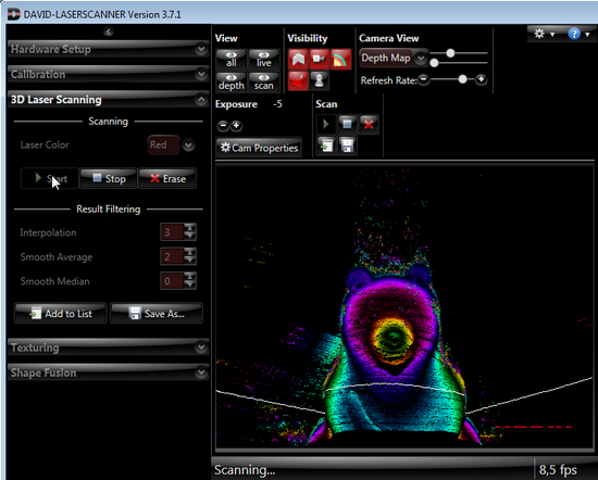 Front lay out these parts as shown in Fig. 161. Then proceed as follows:
Fig. 161 Parts of the scanner stand
-
Raise the two side walls to a vertical position as shown in Fig. 162. Paying attention to the orientation of the T-slots, install the front wall onto the two pairs of side wall hooks. Press on the front wall and slide it down until it stops. Make sure all three walls are on the same level.
-
Install the back wall in the same way (see Fig. 163).
-
Paying attention to the orientation of the slots, fit the cover onto the top hooks on the side walls (see Fig. 164).
-
Use your thumbs to press the cover in the area of the T-holes and slide it towards the rear wall until it clicks (see Fig. 165).
Fig. 162 Front wall assembly
fig. Fig. 163 Rear wall assembly
Fig. 164 Fitting cover
165 Locking the cover
The scanner stand is now ready for use.