Rumba 3d printer control board
Rumba - Geeetech Wiki
Contents
- 1 Introduction
- 1.1 Appearance and Hardware Resources
- 1.2 Software Resources
- 2 Interface Resources
- 2.1 Interface Resources Instruction
- 2.2 Jumper Instruction
- 3 Setting up Operational Environment
- 3.1 Interface Connecting and Setting
- 3.2 File Program
- 3.3 Setting Software
- 4 Quick Started Guide to program
- 5 Extensible Applications
- 6 FAQS
- 7 How to buy
Introduction
As the core of 3D printer, Rumba’s running is controlled by electric part. Rumba uses the integrated control board on the base of ATmega’s AVR processor. The circuit board is developed for 3D printer, carver, laser cutter and other CNC. Controlling the 3Dprinter with USB or printing through SD memory card. With integrated design, it is easy to install and debug. Using Arduino IDE as the development software, the firmware update and parameter configuration are both easy to use. Compared with other 3D Printer control board, Rumba has one more motor driver and less plug-in part so that it can improve the connectivity and stability. Detailed parameters are as follows.
1 Use the same CPU as that of Arduino MEGA as main control chip, Atmega2560 cooperates with high-performance USB chip in order that it is compatible with all RAMPS relevant firmware;
2 Five interfaces as input for temperature sensor.
3 All pins being drawn out to permit more function expansion.
4 With expanding interface, it can connect the LCD displayed and the development board.
5 Servo’s expanding interface to make the automatic leveling easier to add
6 Supporting 6 pieces of 16 micro stepping drivers of A4988.
7 PWM DC output( heating pipe ,fan), six channels of output( 1 channel of high current, 3 channels of medium current and 2 channels of low current). Use low on-resistance MOS Varactor as driver and LED tests each output.
8 Power-supply: power input 12v-35v, dual power to avoid interaction; hot bed connects 11A, 12V, other sections connect 5A, 12V and add a 12V cooler to reduce the high temperature from the high current of Mega controller.
9 Adopt the popular control board firmware-Marlin, which has good stability, usability and function.
Appearance and Hardware Resources
Size: 135*175mm
Weight: 90g
Software Resources
Drivers
Printrun
Repetier-Host
Arduino IDE 1.0.5
Arduino IDE 1.5.6
Marlin
Interface Resources
Interface Resources Instruction
1. Five interface for temperature measurement: three for extruders, one for hot bed and one for environment.
2. Five PWM: three for the heating of extruder and hot bed, one for Fan rotation and one for lighting.
3. Six end stops: Xmin/Xmax/Ymin/Ymax/Zmin/Zmax, which can connect ends tops of machinery and optics or the Hall Sensor.
4. Supporting JTAG makes it possible to conduct software development.
Jumper Instruction
1. MCU power options: connect the jumper cap of 1 and 2 to provide external power. Connect the jumper cap of 2 and 3 to provide USB power.
2. Pulling out Jumper cap to make MCU into Mode DFU
Setting up Operational Environment
Interface Connecting and Setting
File Program
1,Windows users need install driver before uploading. The board: Tools > Board > Arduino Mega 2560 or Mega ADK as shown below.
2,Configuring serial interface: Tools > Serial Port > your corresponding Comm Port of mega board of is the last one usually.
3,Click the “check ( )” button to check if it is right or wrong and then click the “ ” button to upload firmware.
4,Upon uploading the correspondent LED to TX, RX and L will blink, if they stop blinking, the uploading completed.
After uploading, you could go on to the next step. If you cannot upload, check the dialog box below IDE to identify the problem and solve it. The common mistakes of board type include the select error, serial port selection error, etc.
Setting Software
for more detailed insturction, please refer to the user manual.
Arduino IDE Installation
1,You can notice USB identification “Arduino Mega 2560” on your computer when connecting the Rumba to computer with USB.
Then, windows will open the dialog box “found new hardware guide”, check “no, not this time”, then click “next”.
2,Check “install from lists or specific location (advanced)”, then click “next”.
3, Specify “drivers” in Arduino 0021 installation directory to install driver.
If every goes well, windows will install the corresponding driver.
The graph below shows installation completed.
At this time we could find the corresponding Arduino MEGA 2560 device in device manager of windows.
Quick Started Guide to program
Rumba board to 3D printer is just like the brain to human. Rumba fulfill the complicated printing through dominating all 3D Printer Accessories。It cannot operate directly without uploading firmware.
1.Download firmware-Marlin. Marlin firmware is born with powerful features and easy to use, therefore we just introduce Marlin firmware.
2.Configure Firmware parameter.
The following parameter need configured, others default.
#define BAUDRATE 250000
It configures for SERBAUD. Note: the successful communication can be realized when the upper computer Baud rate is identical with Firmware Baud. The Baud can’t be modified freely. The common Baud : 2400,9600,19200,38400,57600,115200,250000. The last three are frequently used by 3D Printer.
#define MOTHERBOARD 80
The parameter is used to configure board type. 3D Printer has many types of main board, but the IOs of all boards are different, therefore, the parameter has to correspond to the type of your board, or it can’t operate normally. The configuration of Rumba should be 80(single nozzle configuration). If it is other board, you can choose a suitable parameter with the annotation beside the board.
#define TEMP_SENSOR_0 3 #define TEMP_SENSOR_BED 3
The two parameters configure the type of temperature sensor respectively. They are the critical parameter to check if the sensor read temperature normally. It is can’t operate even has potential risk (burn the device and others) when the temperature readout is normal. You must modify depends on circumstance if you used other temperature sensors.
#define EXTRUDE_MINTEMP 170
The parameter is to avoid the potential risks when the extrusion operates before reaching the appropriate temperatures. If it is used for other 3D Printer, such as printer of Chocolates, 45℃ is appropriate, so that the parameter configured to a lower value(such as 40℃).
const bool X_ENDSTOPS_INVERTING = true; const bool Y_ENDSTOPS_INVERTING = true; const bool Z_ENDSTOPS_INVERTING = true.
The three parameters configure the end stops types of three axes. The configuration is true, the end stop outputs 1 in default condition and outputs 0 in trigger condition. That is, mechanical end stop connects the AOF. If it connects the AON, true should be changed to false.
#define INVERT_X_DIR false #define INVERT_Y_DIR true
It is easily to make mistakes in the above two parameters. The parameters are different in different machinery. However, in principle, the origin should be at lower-left corner of the print platform (origin: 0, 0), or at up-right corner (origin: max, max).then, the model printed is correct, otherwise, the printed is the mirror image of one axis, with the result that the wrong model direction.
#define X_HOME_DIR -1 #define Y_HOME_DIR -1 #define Z_HOME_DIR -1
If the origin is the minimum, the parameter is -1; if it is the maximum, the configuration is 1.
#define X_MAX_POS 205 #define X_MIN_POS 0 #define Y_MAX_POS 205 #define Y_MIN_POS 0 #define Z_MAX_POS 200 #define Z_MIN_POS 0
These parameters are crucial to the printing size configuration. Fill in parameters by reference to the coordinate graphs. It is important to note that the origin is not the printing center and the real printing center usually at [(x. max - x.min)/2, (y.max -y.min/2)]. The coordinate of central position will be used in the slice tool. The printing center’s coordinate must correspond to the parameter configuration, or it will print to the outside of the platform.
#define HOMING_FEEDRATE {50*60, 50*60, 4*60, 0} The rate of configuration back to origin, unit: mm/min. This parameter could be set default when you use the x-axis, y-axis synchronous belt drive and z-axis screw drive.
#define DEFAULT_AXIS_STEPS_PER_UNIT {85.3333, 85.3333, 2560, 158.8308} These parameters are crucial to check if the printing size is correct. Parameters means that the pulse number needed at every axis when operating 1mm. they are correspond to x, y, z and e respectively. In most cases these number should be computed by yourself, but you can refer to: http://calculator.josefprusa.cz/#steppers So far we have configured the common parameters and could operate it. In addition, if the 2004LED need verifying, you should delete the “//” from “//#define REPRAP_DISCOUNT_SMART_CONTROLLER” to ensure the normal working.
Extensible Applications
Exp: IIC、PWM、GPIO
JTAG:
FAQS
1. Q: The LED light is off when connected USB and external 5V power.
a. The jumper cap of MCU power options has not plugged.
b.The LED does not work or not weld correctly.
2. Q: LCD screen does not display.
A: The code has not burned-in and the connection of LCD is poor.
3. Q: Fail to install driver.
A: you may encounter a problem “system cannot find the specific folder” in the process of Arduino driver installation when you use starter edition windows, because the starter edition of windows system has deleted some uncommon information for driver. The resolutions are as follows,
A: open C:\windows\inf\setupapi.dev.log The file not only includes plug and play device, information for driver installation, but also record the reason for the failure of Arduino driver installation. Open this file and move to the end of the file you will observe the following information as in the flowing picture.
It is just the file error that causes the failure of Arduino driver installation.
B: creating a folder” mdmcpq.inf_x86_neutral_******** “in the path of
C:\Windows\System32\DriverStore\FileRepository\
The identifications of all computers are different, so please refer to the prompt box from the “setupapi.dev.log” to know the “******* “. For example, information provided by my computer is
“C:\Windows\System32\DriverStore\FileRepository\mdmcpq.inf_x86_neutral_9f203c20b6f0dabd “
According to this prompt, I created another folder with the same name in the path of C:\Windows\System32\DriverStore\FileRepository\, as follows,
C: Download and decompress the following file and add it to the created folder mdmcpq.inf_x86_neutral_********. 32bits windows:
Media:Mdmcpq.inf x86.rar
Media:Mdmcpq.inf amd64.rar
D. Reinstall driver step-by-step. At this point, driver can be installed. If the computer system is windows 8 and driver cannot be installed, there are some other alternative methods for you.
Click Windows and R
Input shutdown.exe /r /o /f /t 00
Click “confirm”
The system enters “option” page automatically
Click FAQ
Click advanced options
Click windows boot settings
Click reboot button
System will reboot and go to the advanced boot options
Click “disable driver and mandatory signature”
Rebooted, install the Arduino driver and the installation method is the same with that of windows 7.
How to buy
Click here to buy: http://www.geeetech.com/geeetech-rumba-the-latest-3d-printer-controll-board-p-848.html
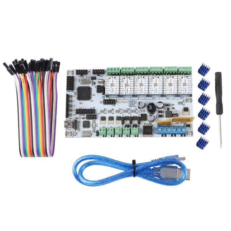
3D Printer Control Board Rumba MPU With A4988 Heatsink
Product Description
3D Printer Control Board Rumba MPU With A4988 Heatsink
Description:
Name: RUMBA
Size: 135 x 175MM
Weight: 90g
Power input: 12-35V
Support electric quantity: 6
Motor driven support: A4988, DRV8825
Control panel support: LCD2004 LCD12864
The build environment: For Arduino IDE
With firmware: Marlin
The upper computer software: Printrun Repetier – Host
Characteristics:
1. Using the same with for Arduino MEGA CPU, Atmega 2560 is used as the main control chip, with the high performance USB chip ATMEGA1602, can compatible with all RAMPS firmware.
2. 5 temperature sensor input interface
3. All the pins are led to, convenient do more function expansion
4. With LCD expansion interface, can be connected Chinese LCD screen and SD development board, the realization of offline printing support 2004 and 12864
5. The steering gear expansion interface, convenient to add automatic leveling function,
6. Supports 6 A4988 16 stepper drive plate, or 6 DRV882532 stepper driver board;
7. PWM DC output, 6 output use high performance and low conduction resistance for MOS pipe driven, each output LED instructions
8. The power supply part: the power input for the 12-35V, the design is dual power supply, effectively avoid the mutual influence, hot bed part supports the 11A current, 12V, the other part, 5A, 12V, in order to reduce the large current in high temperature MEGA Controller board produces, proposed to increase the 12V cooling fan
9. Control board firmware will use now the most widely used Marlin, stability, ease of use, function and have a very good performance
The interface layout and description:
1. 5 channel ADC interface for Temperature Measurement: 3 extruders for temperature measurement, one hot bed temperature measurement, one ambient temperature measurement.
2. 5 channel PWM, 3 control heated of extruder and hot bed, one control fan rotation, one for lighting
3. 6 channel Switch: Xmin / Xmax / Ymin / Ymax / Zmin / Zmax can connect a mechanical or optical limit switches or Hall sensors
4. Support JTAG operation
Jumper cable instruction:
MCU power selection, with a jumper cap short connect 1 and 3, choose the USB power supply, short connect 2 and 3, choose an external 5V power supply
Pull out the jumper to make the MCU enter DFU mode
Package included:
1 x 3D Printer Control Board Rumba
6 x A4988
6 x Heatsink
1 x USB cable
3 x Stickers
More Detailed Photos:
Additional Information
When you order from Alexnld. com, you will receive a confirmation email. Once your order is shipped, you will be emailed the tracking information for your order’s shipment. You can choose your preferred shipping method on the Order Information page during the checkout process. Alexnld.com offers 3 different international shipping methods, Airmail, Airmail registered and Expedited Shipping Service, following are delivery times:
| Airmail and Airmail Registered | Area | Time |
|---|---|---|
| United States, Canada | 10-25 business days | |
| Australia, New Zealand, Singapore, United Arab Emirates | 10-25 business days | |
| United Kingdom, France, Spain, Germany, Netherlands, Japan, Belgium, Denmark, Finland, Ireland, Norway, Portugal, Sweden, Switzerland | 10-25 business days | |
| Italy, Brazil, Russia | 10-45 business days | |
| Other countries | 10-35 business days | |
| Expedited Shipping | 7-15 business days to Worldwide | |
We accept payment through PayPal,and via credit card.
Paying with PayPal / Credit Card -
NOTE: Your order will be shipped to your PayPal address. Ensure you have selected or entered the correct delivery address.
1) Login To Your Account or use Credit Card Express.
2) Enter your Card Details the order will be shipped to your PayPal address. and click Submit.
3) Your Payment will be processed and a receipt will be sent to your email inbox.
Returns
You may return this item within 15 days of delivery for a full refund. We’ll also pay the return shipping costs if the return is a result of our error (you received an incorrect or defective item, etc.).
If you need to return an item, please Contact Us with your order number and details about the product you would like to return. We will respond quickly with instructions for how to return items from your order.
Product not working as expected?
Our Customer Service team are able to resolve most product related issues quickly and efficiently. For the support, please contact our team using the submission form on our Contact page.
Returns Eligibility
In order for a return to be eligible for a refund please ensure you return within 15 days from the delivery date of your item.
We kindly ask that you return your item to us in new or lightly used condition with no signs of worn out. If the item is in used condition, please send us the photo to confirm its condition before returning it. We reserve the right to refuse any return if there are any signs of worn out or if parts are missing.
Please be aware, we do cover the cost of the returns fees only if the return is a result of our error (you received an incorrect or defective item, etc.).
All customers should contact us before sending anything to us. We will not be responsible for returned item(s) without notifying us in advance.
Refunds
Following a successful inspection of your return we will process a full refund to the credit / debit card or PayPal account which was used to place the original order.
You should expect to receive your refund within four weeks of returning your package, however, in many cases you will receive a refund more quickly. This time period includes the transit time for us to receive your return from the shipper (5 to 20 business days), the time it takes us to process your return once we receive it (3 to 5 business days), and the time it takes your bank to process our refund request (3 to 5 business days).
Disclaimer: These are user reviews. Results may vary from person to person.
Product Enquiry
Name
Email address
Enquiry
Board for a 3D printer: choosing a control motherboard
When buying or assembling a 3D printer with your own hands, special attention should be paid to the device's motherboard. Since this component is responsible for printing products in general. Consider what functions the motherboard performs, what types of this component exist, and what parameters you need to pay attention to when choosing it.
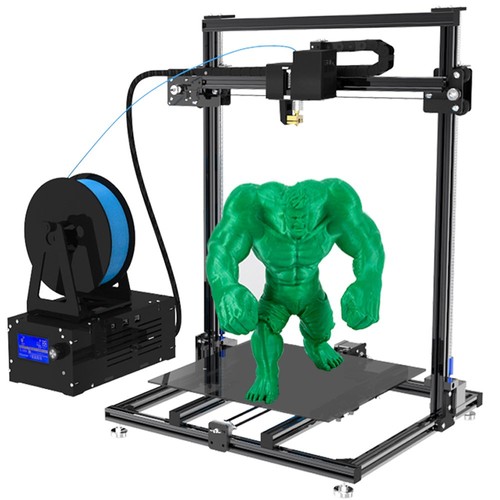
3D printer motherboard
The controller motherboard is the main control element for the extruder, motor, sensor and heated filament bed in any 3D printer.
Motherboard is executing user-specified commands. After the internal set of microchip elements converts electrical impulses into mechanical movements of stepper motors. As a result, a three-dimensional computer model will be printed layer by layer on the working surface of a 3D printer.
Choosing a control board
Among the most popular motherboards for 3D printers, there are five models:
- Arduino Mega 2560 + Ramps 1.4.
- Melzi.
- Lerdge X.
- Duet.
- Rumba.
Let's take a closer look at the features, pros and cons of each board.
Arduino Mega 2560 + Ramps 1.4
Board with Ramps 1. 4 component operates from 5 V. It is equipped with five slots for installing stepper motors. At the same time, three slots allow the motors to control the axes of the printer, and the other two to drive the extruders. In addition, the board contains many additional pins for controlling various elements, such as a table auto-level sensor, axle limit switches, servos, etc.
To control all the printer's built-in electronics, the board contains contact pads into which the Ramps shield component is inserted.
The three main advantages of the board are:
- low price;
- a wide range of interchangeable components that can be replaced in the event of a breakdown;
- additional pins for controlling various printer components.
The board has only one significant drawback - its bulky design.
Melzi
The Melzi motherboard is equipped with four stepper motor controllers, three of which are located on the XYZ axis and one on the extruder. This model is sold already with customized firmware. Therefore, the user only needs to correctly connect the wires to the output connectors.
You can print 3D objects using a memory card via a micro-USB connector or by connecting the card directly to a computer.
The Melzi board is ideal for the beginner building a printer for the first time. Since it does not require additional calibrations and can be used immediately after purchase. However, the motherboard also has significant drawbacks:
- no display can be connected to the board;
- You can reflash the motherboard only through the ISP port, but this will take a lot of time and a layer of special knowledge;
- If the motor controller fails, it cannot be replaced.
Lerdge X
Lerdge X is a motherboard with a 32-bit STM32F407 chip that allows you to quickly read lines of code. The device is additionally equipped with four drivers and a color display with touch control. The board supports only one extruder and it is not possible to install a second one if necessary.
Before using the board, you need to calibrate it, set the dimensions of the working area, adjust the temperature sensors of the extruder and table, and set the speed parameters of each motor.
You can print files using a flash drive, memory card or via a computer.
Pros of using the Lerdge X board:
- motherboard fits any type of printer;
- board chip supports various kinds of popular slicers;
- built-in display with touch screen.
The disadvantage of using the board is that only one extruder can be used.
Duet
The Duet board is equipped with its own open source firmware, which is available for free to any user on Github.com. The 32-bit Atmel SAM3X8E chip is responsible for the stable operation of the motherboard.
Built-in device drivers allow four extruders to print simultaneously. For more convenient control, the user can install a touch screen with a diagonal of 4.3, 5 and 7 inches.
Pluses of the board:
- free firmware;
- four extruders available at the same time;
- two board configurations to choose from (Ethernet or Wi-Fi).
Duet motherboard cons:
- Before installing the board, it requires full configuration and firmware.
Rumba
The Rumba 8-bit motherboard allows the 3D printer to use three extruders at the same time. However, installing them separately will not work, but you can only install a Diamond Hotend multi-extruder with support for three filaments.
This type of board is based on the Arduino processor. It comes with Marlin firmware installed. If the user needs to reflash the board, then for this you can use the standard mini-USB connector.
Among the advantages of Rumba are:
- the presence of connectors for connecting a display and a slot for a memory card;
- removable motor drivers that can be easily replaced if broken;
- simple flashing if necessary.
The main disadvantage of the motherboard is that for printing with multiple filaments, you will need to purchase an additional multi-extruder.
What to look for when choosing a 3D printer board?
When choosing a motherboard for installation in a 3D printer, the user is advised to pay attention to six device parameters:
- The number of supported extruders. Ideally, there should be four or more. In this case, full color printing will be available.
- Integrated or plug-in drivers. It is desirable that the drivers in the board are removable. Since in the event of a breakdown, they can be easily removed and repaired or replaced in the event of a complete malfunction.
- Number of engines.
 It is recommended that the board has at least four motors, ideally six.
 - Wi-Fi available. The built-in module will allow you not to constantly connect the printer to the computer each time you print.
- Firmware support. It is desirable that the board supports various types of firmware. Both paid and free.
Help. Each specific type of board can support one or more types of firmware. Their number depends on the board manufacturer. For example, Arduino boards support Marlin, Marlin Kimbra, Marlin RichCattell, Repetier-Firmware, Teacup, Aprinter, Sprinter firmware. Arduino Due motherboards can work with Marlin4Due, Marlin Kimbra v4.2.x, Repetier-Firmware, RepRap Firmware. And 32-bit ARM processors are compatible with Smoothie Project and Redeem firmware.
- The presence of protection against incorrect inclusion of elements.
In this article, we have listed only the most popular motherboards for 3D printers. However, on the electronics market there are boards for any user requests, the choice of which can be guided by the recommendations presented above.
- March 29, 2021
- 4106
Get expert advice
Russian 32 bit 3D printer control board with HMI display, with own firmware.
Good afternoon!
I would like to present to your attention my new development: software and hardware complex for building industrial-class 3D printers. With the help of such a complex, it is possible to quickly implement various designs of 3D printers that print with granules, filament, composites or food compositions.
The complex was designed as a test platform to simplify the implementation of various new ideas in 3D printers and is a combination of a touch screen HMI and a control board on an STM32F4 series microcontroller.
Display
Initially, the control board program supports only one type of HMI display, 2. 4" to 10.1". These are displays familiar to many - Nextion displays. Basically, HMI displays are LCD touch screens with their own microcontroller, the visual control interface of which is typed in a special program from ready-made elements: buttons, graphics, numbers, scales. Thus, using such a ready-made device for the developed control board, it becomes possible to simply and quickly change the menu structure, the color and size of buttons, their number, and the overall design.
An example of a start window developed - a single-extruder 3D printer with an active camera.
A novelty in the start window is a warning sign (1) that appears during self-diagnosis if there are problems in the system and an additional area - event icons (2) that occur when the board is connected to the computer, the fan is turned on, the plastic presence signal, etc. d.
Video of selecting a file for printing. Display with a diagonal of 4.3 inches.
- In addition to the direct access of the display to the board during the operation of the standard printer menu embedded in the firmware, it is possible to send standard G-codes from the display, which are processed in the pipeline-processor of commands on the control board.
 How it works: you can bind G- to any newly created buttons code, command or their sequence, which are sent to the board to perform an action when a button is pressed. Also, G-code can be assigned to any events or actions on the screen.
 - A lot of different information comes up on the screen during printing and when the printer is idle, for example: percentage of print completed, layer height, extruder temperature. In addition, marks of the beginning and end of printing, marks when moving through the layers of printing, values in samples from the ADC on the board are additionally sent. Having this information, using the built-in functions of the HMI display (conditional statements, counters, timers), you can organize additional automation of the printer. All conditions can be started and stopped using the created buttons.
This extended screen support from the board allows you to create personalized solutions in the menu: buttons with preconfigured parameters, calling macros from the processor memory or writing a macro in the display, performing simple printing automation.
Some examples of using the HMI display for automation.
- Implementation of the nozzle cleaning macro on certain print layers. The advantage is that cleaning can be turned on or off, as needed, from the screen. In addition, you can set how long this macro will take after printing has started.
- Implementation of the backlight control algorithm. Changing its brightness and color depending on the ambient light and the percentage of printing completed, signaling problems in the system.
- Implementation of automatic printer shutdown at the end of printing using the M81 command.
- Management of 3D printer board ports according to a pre-configured algorithm or events.
Nextion displays have different diagonals, and in order not to produce different firmware, we have made a menu that can be adjusted to the required tasks by changing several parameters in the control board config file. For example, to change the number of lines displayed on the display of files located on a USB drive, you need to specify their number in the config file, then the program starts working for the specified number of lines. Thus, a menu is compiled for various screen sizes, fonts and screen orientations by changing only a few parameters in the configuration file.
Implemented support for switching the interface language (English and Russian) from the printer menu.
Control board
The heart of the board is the processor of the STM32F4 family. Overall dimensions 120x150 mm. The board was created as an experimental platform with which you can implement various configurations of 3D printers. When creating, the main emphasis was placed on its reliability and long-term operation as part of a 3D printer, which led to the widespread use of TRANSIL diodes and assemblies for protection against impulse and static interference. Traditional MOSFETs have been replaced by smart switches with electronic short-circuit protection and output diagnostics. The use of smart keys made it possible to get rid of fuses, which also has a positive effect on the reliability of the control board during operation.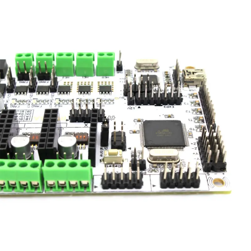
Power terminals for connecting power and powerful loads to the board, used by WAGO-256 - these are modular terminal blocks for printed circuit boards with a convenient push lever for attaching the wire.
All consumers are divided into four groups - PWR1-PWR4. This design allows you to easily combine loads with different operating voltages, as well as implement a standby mode (Standby Power), in which the printer will consume a minimum of energy after printing is completed. In the board, all loads are switched through switches controlled by the central processor. With the help of a special output for an external relay, you can organize two shutdown options: the first is to turn off all electronics from the network and then start it through an external button, and the second - the processor puts all loads into an inactive state: fans, display, USB flash drive, etc. then the processor itself falls asleep, but, at the same time, the board can resume its work on a remote turn-on signal or on a signal from a connected computer. Also, if there is a standby power supply connected to the PWR1 input, the relay can also disconnect the second powerful power supply for the PWR2-PWR4 input from the network (additional energy saving). The second power saving mode with the ability to resume the 3D printer on command will be useful in building 3D printed farms.
The board does not have standard sockets for a USB flash drive and a socket for connecting a computer; WAGO spring terminals are installed instead. This solution allows, using extension cables pressed with tips, to place all the necessary sockets in convenient places on the printer without binding the board to the front panel.
As described above, all loads are switched by intelligent keys and, at the same time, information on the self-diagnosis of the system is additionally taken from them. Depending on the type of keys in the channels, the diagnostic information from them is different.
- The smart keys for the hot end channel, the heated platform and the printer chamber heating are the same, the maximum consumer current for each channel is 20A.
 Diagnostic information from them is as follows: load break, short circuit in the load, key overheating, power - consumed by the load connected to them.
 - For three fan channels, maximum current consumption 1A. Diagnostic information from them is as follows: load break, short circuit in the load, key overheating.
- For two fan channels and a power channel for limit switches, you can separately set the voltage of 5/12 V, the maximum current consumption for the channels is 0.5 A. Diagnostic information from them is as follows: load break, short circuit in the load, overheating of the key.
- To power the display, a key with output parameters 5V 1A is used, for a USB flash drive 5V 0.5A. Diagnostic information from them is as follows: short circuit in the load, overheating of the key.
Since the board is mainly designed for industrial equipment, the number of drivers on the board is limited to four pieces, but, at the same time, their control pins STEP, DIR and EN are duplicated by buffer microcircuits into sockets for direct control of external stepper motor drivers, logic voltage these outputs are 5V. Also on the board there are additional 10 outputs formed through buffer microcircuits for external connection, with logic levels of 5V, all outputs are protected by TRANSIL diodes.
For external connection of remote sensors with dry contact, the board provides 6 inputs, with optical isolation. Such inputs may be required, for example, to measure the level of granules in the hopper or to connect end sensors on the “large” printer frame.
USB connection to the computer is galvanically isolated from the board and protected by TRANSIL diodes.
Three-channel temperature measurement using a PT100 platinum sensor and MAX31865 custom ICs. Connection is possible with a two-, three- or four-wire circuit of a measuring temperature sensor. Diagnostic information from microcircuits, the following: sensor short circuit, sensor wire break. The use of platinum thermal resistance as a temperature sensor was due to the following considerations: temperature measurement up to +600°C, a wide selection of sensor body versions, no need for calibration, high measurement accuracy, connection via a long cable up to 100 meters.
Communication between the board and external equipment is carried out using the RS485 interface. The choice of this interface is due to its widespread use in the industry. RS485 is supported by various sensors and process controllers (mostly with Modbus protocol).
Output electrolytic capacitors are installed in a special series, with a service life of 6 times longer than standard surface mount electrolytic capacitors.
of the NEXTION Display has a UART interface, but for communication between the control board and the display, an RS232 interface (a standard interface for industrial displays) is implemented, which allows a cable length of up to 15 meters. Therefore, an RS232 - UART adapter is required, which will come with the board. Such a solution will be more reliable when operating in conditions of increased interference.
Also on the board there are two ADC inputs, one for the thermistor, the second for the ambient light sensor.
The board has additional inputs and outputs. Their purpose is one of the subjects of future publications.
Purpose
- The presented board and program for the STM32F4 microcontroller is the fourth generation of the complex initially developed for itself. Together with the HMI display, the complex turned out to be quite versatile in use. On this complex, I plan to reproduce two- or more-extruder 3D printers with automatic measurement of nozzles by a load cell (some analogue of the solution from Josef Prusha (link)). A custom extruder is created for the load cell, and for its manufacture I conducted experiments with aluminum soldering (link). Theoretically, if the extruder has minimal weight and size parameters, and the fans do not create significant vibrations on the measuring part, then a large amount of information can be obtained from such a design, not only about the sizes and coordinates of the nozzles, but also, presumably, indirectly about the pressure of the filament in the melt zone. I will test this hypothesis in the near future.
 At this stage, I can only say with certainty that it will be possible to implement automatic measurement of nozzle coordinates. I plan to introduce my filament motion sensor into the extruder, which allows to determine the underextrusion of plastic during printing (link), with the display of a new parameter - plastic slip. I think that together with a load cell, you should get an excellent SMART extruder. In the future, it is interesting to reproduce some analogue of the Ultimaker S5 Pro Bundle system, for 24/7 printing (link), but with its own solutions in the form of boards, sensors and work algorithms.
 - The board has already been used in one of the commercial projects, so the idea of a third purpose was born.
- I invite Russian companies, startups to cooperate. All the solutions I have worked out will allow you to implement your plans in a short time, build a prototype, with its subsequent launch into mass production and joint efforts to compete in the global market for 3D printing solutions! The goal is ambitious, but quite achievable, the main thing from you is an idea and a desire to work! The following areas are interesting: 3D printers printing pellets, large industrial printers with an active camera or MFP printing and milling devices, 3D printers printing food materials, 3D farms.

About the details and plans
The control board may have turned out to be redundant in some circuit solutions, therefore it is relatively expensive and it is not practical to use it to assemble simple, home single-extruder printers, therefore, at this stage it is not available for free sale it will be, since it is cheaper to buy other ready-made kits, but as the project develops and my new functionality grows, I will make the option more accessible.
My plans for the next month are to assemble the board and firmware for its new version, finish the menu. Also, I plan to order a second, small experimental board for a SMART extruder. I decided on its elemental base, it will have a processor on board, smart keys for the extruder heater and two fans, two accelerometers, a strain gauge amplifier and a number of elements for various sensors, communication with the main control board via RS485.
By firmware
The firmware is written on our own. The G-code of the team was borrowed from Marlin 1.0 five years ago, the calculation of the trajectories of movements was also taken from there, so the board does not support other displays than those that we are implementing. The same feature is with sensors. At the moment, we are introducing the possibility of compensating the resonance of the 3D printer mechanics and supporting two other options for HMI displays into the microcontroller program of the board, more expensive than NEXTION - industrial grade and cheaper than NEXTION - this type is being introduced for affordability of the board and display kit. Writing a program for the microcontroller was very slow for us, the board was constantly changing, the solutions for the sensors also changed, but since now all these issues have been resolved, the main emphasis in the work will be aimed at developing and optimizing the firmware.
Some statistics on the board
Capacitors - 84 pcs.
Resistors - 135 pcs.