Convert 3d printer to cnc router
Why 3D printers can’t be CNC mills – Tom's 3D printing guides and reviews
Hey, how’s it going, everyone? Have you ever wondered why 3D printers and actual CNC machines seem to be so similar, but rarely you ever see anyone successfully using a 3D printer as a milling machine and vice-versa? Well, today we’re going to look at why that is and maybe at what a compromise could look like to handle both!
So the three printers, well, the three machines I have here today are the CR-10, a fairly common and actually surprisingly okay 3D printer, my converted MendelMax 3, which used to be an oversized 3D printer and is now a super-light-duty engraver, mill, whatever you want to call it, you can watch the conversion process here, and yes, it’s not perfect by any means, and lastly, the Sienci CNC, which from now on I’m just going to call Bob because I’m sick of every time having to clarify whether I’m talking about the CNC category or the Sienci product (hrmpf, “Slic3r”), ‘scuse me, and this is a light-duty mill.
I know, I’m using the terms “milling machine”, “router” and “engraver” somewhat interchangeably here, at least for these machines, because they are neither, actually. They’re not built like a router, which typically has a moving portal, which is this part right here, and that’s great for cutting sheet goods; they’re also not built like a milling machine, which has a smaller work surface, but much sturdier construction with a rear column and often a moving work surface, which is heavy and slow, but great for machining metals.
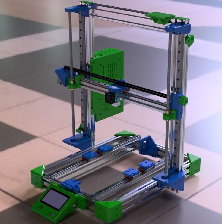
Neither Bob nor the MendelMax is either of those, but both of them are built like your typical Mendel-style 3D printer with a fixed portal and a moving bed, the MendelMax has the X-axis mounted on top of the Z-axis, and Bob has the Z-axis on top of the X-axis, but otherwise, their basic kinematics are the same.
Differences between Bob and MendelMax
openbuilds-style V-slotAnd while we’re at it, let’s actually take a look at how these two are built differently.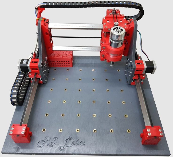 First difference: The frame. Both 3D printers here use machine profiles and both are actually using the openbuilds-style V-slot, which already is a good bit sturdier than your regular 8mm smooth, unsupported round bars, and Bob has these massive aluminum angle profiles with the wheels running on the edges of that.
Proper milling machines would either have linear carriages like these or sliding dovetails, which look like this. And why? Because rigidity. On a 3D printer, there are no forces between the toolhead, that is your hotend, and your workpiece, so the printbed and your print because the hotend is basically just skimming over the part and lays down molten plastic as it goes. On a milling machine, you have the cutting edges of your tool actually digging into the material you’re cutting and that does, in fact, generate quite a significant amount of force.
Use the ForceLet’s see what that force does with these machines: For reference, here’s a Prusa MK2… The CR-10… Mendel Max 3… Bob… and my glorified drill press “milling machine”.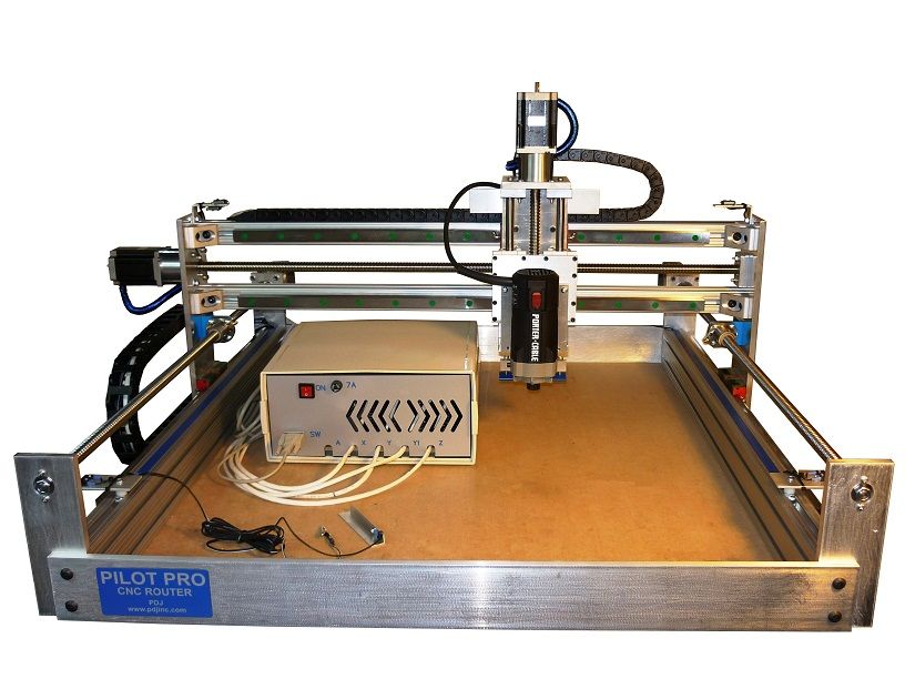 That’s quite a difference. The floppier a machine is, the more it is going to deflect when cutting and that means the more likely it is going to start ringing or doing some other weird stuff that is completely inappropriate for milling. What also plays into this is that 3D printers typically use belts, and especially the cheaper belts are often incredibly elastic – which is the same as having a non-rigid frame. Some CNC routers use steel-reinforced belts, but typically you see trapezoid leadscrews or even ballscrews. Simply speaking, these don’t flex at all.
belts flexing
Steel-reinforced belts
And you always have to keep the key difference in mind when looking at 3D printers vs. CNC machines: 3D printing is, by definition, an additive process, meaning you’re adding material to your workpiece as it gets processed; milling, turning, etc, on the other hand removes material as the part gets processed. So with 3D printing, you only put in as much material as the finished piece is going to use, plus supports, brim, priming, whatever, that’s a tiny amount of waste, but with any subtractive process, you actually need a larger blank of solid material that then gets gradually shaved away.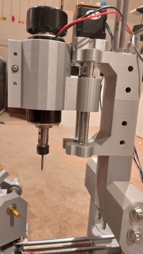 So basically, with a milling process, any part is already in here in the blank, it just needs to be freed from all the waste material around it, which, is actually a pretty cute way to think about it. Where does that extra material go? Well, shavings. If you’re machining wood, you’re often also getting a ton of dust, but aluminum shavings aren’t much nicer to deal with, either, because they are sharp, pointy, small, and large in numbers.
It’s one of the things you’re very likely to underestimate if you’ve never used a CNC and are thinking about converting a 3D printer, for example. There’s going to be a lot more of these than you expect and they will get everywhere. Oh, and the noise. It’s pretty intense.
So, let’s actually make something with these machines, shall we?
Make thingsSponsor Message
And while that’s printing and milling, let’s talk about today’s sponsor, Skillshare! Skillshare is an online learning community and right now, they’re offering over 19.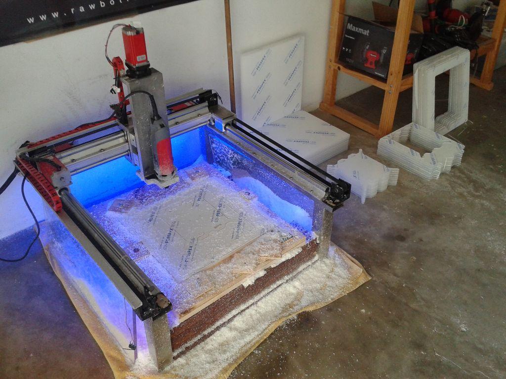 000 classes for you to learn more about the things you enjoy. Daniel has been using Skillshare to get up to speed with videography and editing and I’ve been taking classes on how to be a better boss for him. One of the classes we’ve both taken is “DIY cinematography” by Ryan Booth, and it’s a great, compact course on the basics of lighting, camera angles and motion in any video or film,and that will help us out make better YouTube videos, but if you’re not into videography, Skillshare also has courses on 3D modelling, for example with Fusion 360, or basically any other topic you want to learn about just for yourself or even for turning your hobby into a full-time job!
Once signed up, you can watch as many courses as you want, and while premium memberships are usually around $10 per month, the first 150 people that sign up with this link will get 2 months for just 99$ct. These spots do go quickly, so make sure you don’t miss out. Thanks Skillshare!
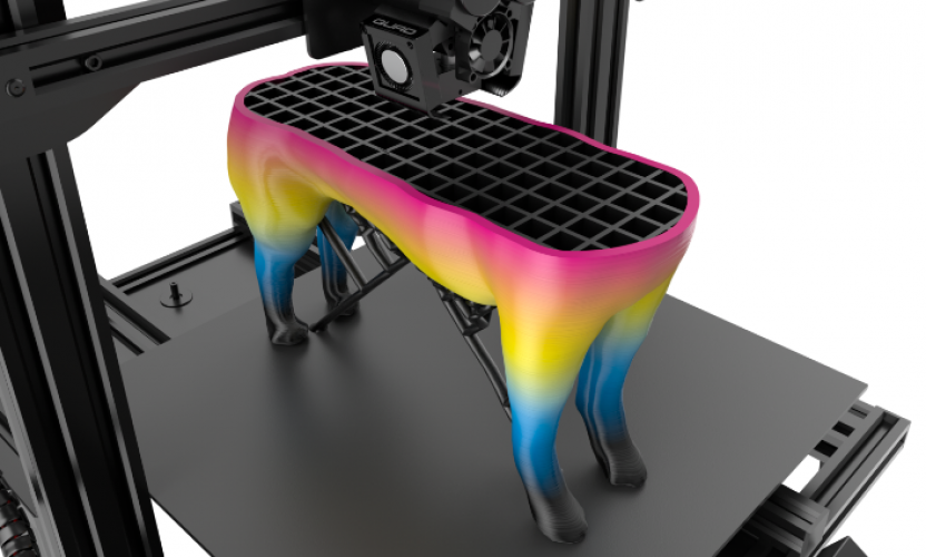
We made something
CNC vs 3DPrintedSo in this case, the milling job was already a bit faster than the 3D print, and this just gets amplified the larger a job is.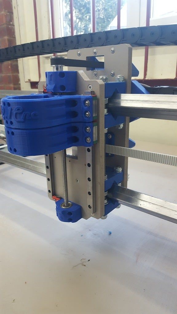 If it’s really intricate parts, a 3D printer does have the upper hand as complexity doesn’t nearly “cost” as much as with a subtractive process, but because a 3D printer will need to lay down every bit of material instead of just not shaving it away, it’s not quite as scalable as a milling process.
Now, a 3D printer, at this point in time, is pretty much always built in the same, very simple sequence: The machine starts at the bottom, works its way up vertically and once it reaches the tallest spot of the part you want to make, it’s done!
Single headWith a CNC, it’s not always that simple. What you often see with these smaller machines is just a single tool being used for the entire job – often that’s an ⅛” square endmill – but on nicer machines, you have all sorts of tools from a cutter head over roughing endmills to finishing endmills, chamfering tools, taps, drills, reamers etc. In which order those tools are used and for what areas is really up to the user, so the process of preparing a file for machining is typically much less automated than the process of preparing a 3D model for 3D printing – which just uses a single nozzle size for the entire print, typically.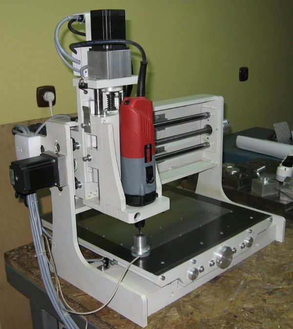 In both cases, how the input file is processed has a huge impact over how the finished part is going to turn out, but with CNC’ing, there’s no simple one-size-fits-all-solution.
3D printers in general are quite the rigid concept – it’s three movement axes, X, Y, Z, plus an arbitrary amount of extruders that basically work as extra linear axes along the length of the filament. On a CNC machine, you usually also have X, Y and Z that position the tool relative to the workpiece, but you might also have, for example, a B and C rotational axis that rotates the tool or workpiece about the Y or Z axis in a four- or five-axis machine. But let’s not forget there’s not just mills, there’s a CNC lathes, combination machines and completely different types as well.
multi axis cncOther “details” are actually surprisingly similar between 3D printers and other CNC machines, like the part cooling fan control on a 3D printer and a coolant pump on a CNC, temperature control of a hotend and RPM control on a spindle, etc, etc, so it’s no surprise that DIY CNC routers are increasingly using electronics, firmware and just general components that might not be directly 3D-printer specific, but at least based on the developments from 3D printing.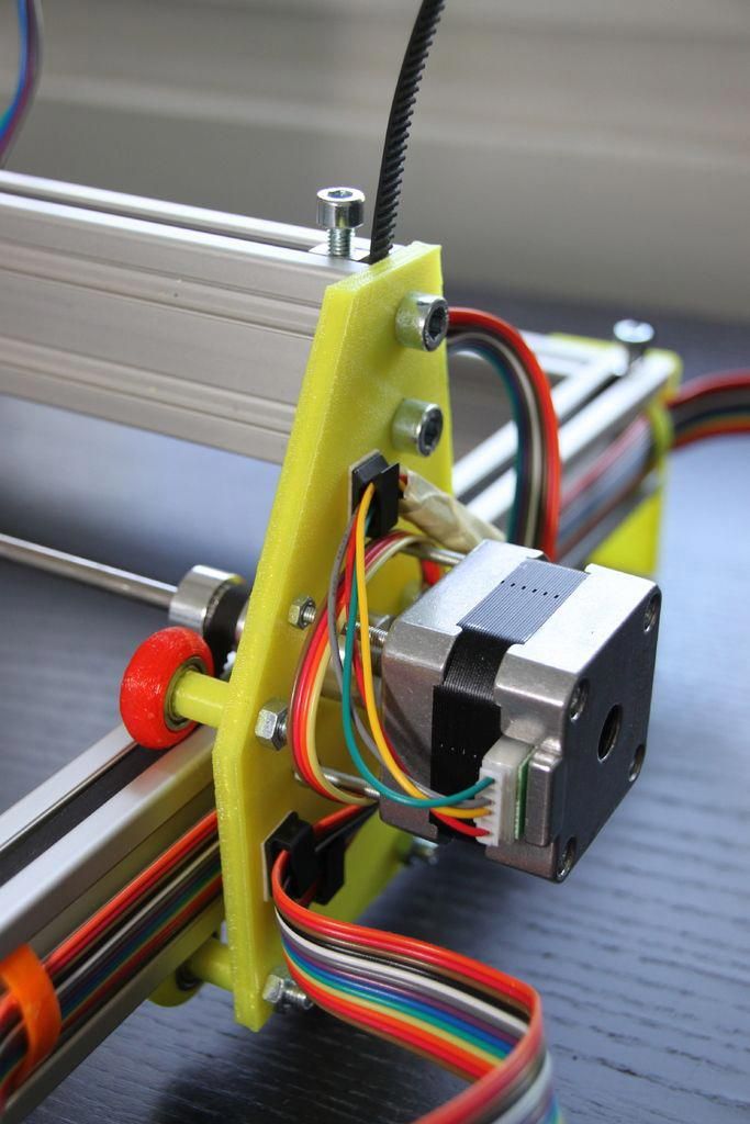 Like with Bob, all the electronics are based on 3D printing boards, the motors are standard NEMA17, the computer interface is the same software serial port – it’s basically a beefed-up 3D printer.
But let’s not forget that 3D printers originally did originate from the larger CNC machines. Things like G-code are directly carried over that, and many of the early 3D printing developments were built to suit both CNC applications and 3D printing – think firmware and even the back-then slicer, Skeinforge. What also carried over is that these machines are maybe not dumb, but at least blind. If a cutting tool breaks, the workpiece dislodges or anything else happens, the machines are often not going to notice it and will just keep going. That is just now getting better for both 3D printers and mills, and bigger CNC machines are using things like load monitoring, the same thing the Trinamic drivers are doing on 3D printers, as well as Servo motors that have a feedback loop etc.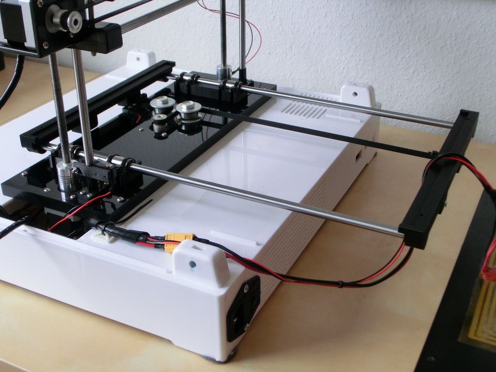
So yes, 3D printers and CNC milling machines are actually quite similar and knowing one of them well will help you get a head start with the other. But the differences in machine construction, especially when it comes to rigidity and top speed, don’t really make combination machines all too viable, at least for “real” applications. Maybe with a somewhat rigid frame and high-pitch leadscrews, you could build something that does both, but it would neither be a great 3D printer nor a great CNC mill.
Wrap Up
Ok, so with that, I think we’re set for trying some more CNC machines! I hope this video clarified some of the differences for you, if it did, give it a thumbs up, get subscribed if you want to see more like it and… and do hit that bell to get notifications when new content goes live. Also check out the affiliate links below where you can get the products we used in this video – like the CR-10! And that’s it for today, thanks for watching and I’ll see you in the next one!
The three CNC/printers shown:
Sienci Mill One
Converted Mendel Max
CR-10
Convert a CNC Router to a 3D Printer
Posted on January 22nd, 2013 in 3D Printing, Custom Projects, DIY CNC, Technology
I didn’t have a ‘large project’ budget for 2013 so I decided that I would do something a bit more low key and convert a CNC router to a 3D Printer.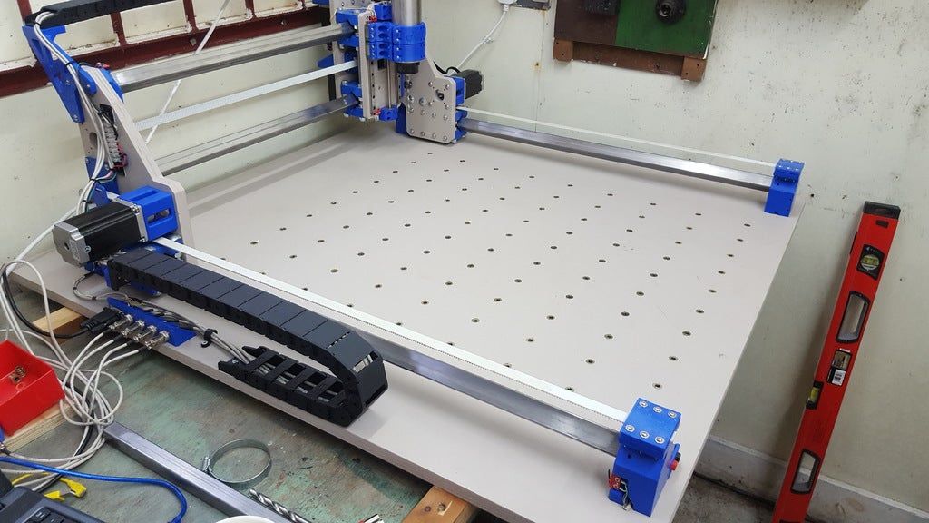 I have been looking at 3D printers over the last few years. They looked kind of cool, but the quality on most filament 3D printers is not what I would call a finished look. They are good for prototypes though, small gadgets or for items where surface finish is not important to evaluate a concept.
I looked at a lot of different SOHO targeted and home made / DIY type 3D printers out there such as the Mendels, Makerbot and RepRap types and about a thousand variations and variations on variations and while there are a LOT of brands, models, makes, open source designs which seem quite capable of printing objects in 3D from plastic filaments, I just didn’t really feel like building a custom built unit when I wasn’t sure how much use I’d actually get out of the thing. Instead I decided to convert my existing CNC router to 3D printing and see how that went.
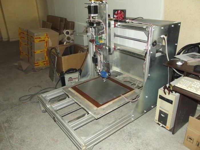
I built a CNC Router from scratch a couple of years ago. It’s a nice and very rigid machine with a bit over 2 foot x 2 foot working area, big stepper motors and very high end linear bearing rails. It originally had a Dewalt router for the spindle, but last year I installed a 2.2kW spindle onto it and it happily chews away on wood, composites and soft metals like aluminum.
Since I already had the motion system in place, a Gecko 540 4-axis controller, the real work was deciding on what I was going to use for a 3D print head. I read a lot of content on reprap.org about various print heads. I read a lot of posts on various forums about people’s own experience with various print heads and I did as much research as I could about the available printing materials; primarily PLA which extrudes at 180C-220C, ABS which extrudes at 215-250C and at even higher temperatures, polycarbonate at around 300C.
I decided to go with PLA filament for my first prints. PLA was the easiest material to start with in my case. It has low extrusion temperature requirements for starters and does not require a heated bed, either. One of the downsides is that it starts to get soft in temperatures as low as 60C so your 3D object may not hold up well in direct sunlight, on a home heating radiator or on the dashboard of a hot car.
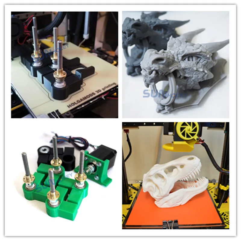
After looking over a lot of extrusion head designs I ordered the parts to make a J-type hot end with some sort of gear driven cold end. The hot end is the part which melts the filament and the cold end is the component which drives the filament into the hot end to be liquified. The more common gear driven cold ends are mostly printed, but you can buy pre-printed ones on eBay or online stores if you don’t know someone with a printer or if you don’t have a working 3D printer at the moment.
I ordered parts to make a J-type hot end but ended up partly building a large MakerBot style Mk7/Mk8 extruder based on a NEMA 23 sized stepper motor with the help of a good friend. I finally ordered a QU-BD extruder. I had seen them marketing at MakerFaire in NYC and thought they were nice looking. I actually ordered the dual extruder, but I am keeping busy enough with just one of them for the time being. I also do plan to finish the NEMA23 extruder as well, possibly using it as an bulk infill extruder for 3mm filament.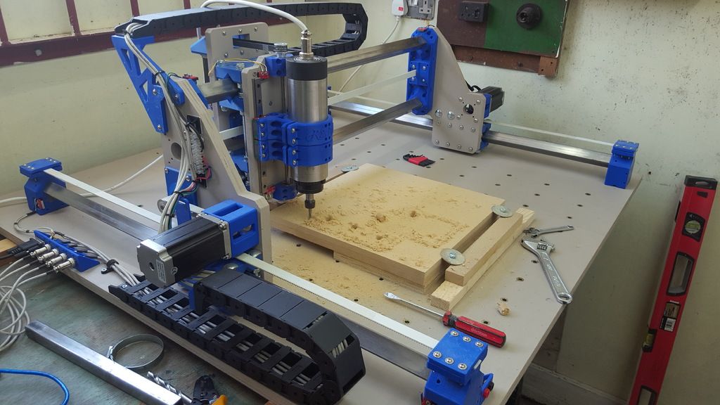
The QU-BD extruder was pretty easy to assemble, there’s only a few parts and they have directions on their website. They did forget to ship the grub screws for the filament drive gears, which are just modified pinion gears, but I had a couple of them in my screw bin. I’m sure QU-BD would have sent the missing part if I requested as their order fulfillment folks seem pretty tuned into that from what I’ve seen on various blogs and forums. Once the extruder is together it’s quite a compact module. You can see it below the PID temp controller in the next photo.
I had to do a couple of modifications to my CNC router to convert it to a 3D printer. I removed the 11+ pound water-cooled spindle and modified the spindle mounting brackets temporarily to accept the QU-BD 3D print head ‘universal’ plate. I then mounted one nozzle, for now, on the adapter plate and ran some extra lines for the new stepper motor (which was attached to the 4th axis of my Gecko 540 controller) and a 12 Volt DC line for the extruder fan, a 24 Volt DC line for the hot end heater and a 120 Volt AC line for the PID process controller which maintains the temperature of the extruder’s hot end.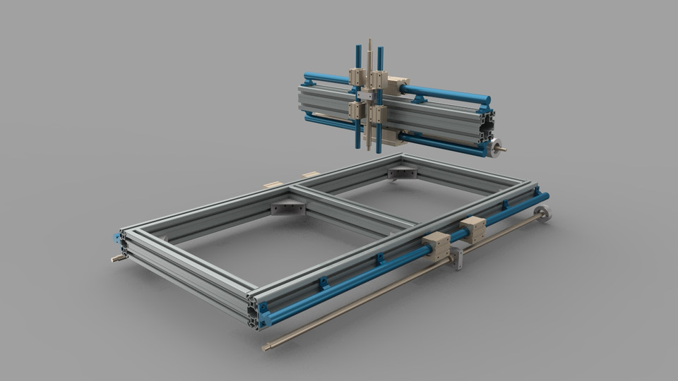 I’ve since removed the big aluminum mounting plate for the CNC Router and mounted the extruder head using some OpenBeam extrusion which I picked up at MakerFaire NYC and this removed another 5 pounds of weight from the x-axis (though the crossbar, bearing and drives still weigh about 35-40 pounds). I also added some LED lighting but need to add even more!
I firmly taped the thermocouple to the heater block of the QU-BD extruder’s hot end with Kapton tape and then wrapped it in the included ceramic material to insulate the hot end. QU-BD only provides enough ceramic insulation to go around the head in one axis so I stuffed a little extra ceramic wool (Inswool) into either end and taped it with Kapton tape to provide extra insulation to the heater block.
With all of that complete, the actual hard work began. The tuning and configuration of Mach 3 and the slicer software of choice. Tuning is perhaps not so difficult as it is trying on one’s patience with the need to tweak, print, tweak, print and repeat the process over and over to find a sweet spot where all of the settings work in harmony to produce a good print.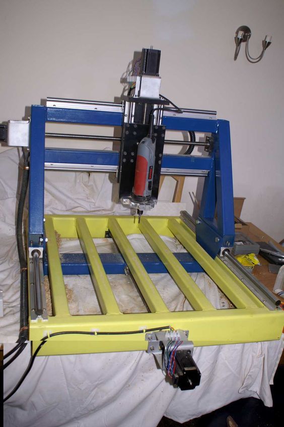 The only thing that keeps me going is seeing that other people have these same problems and that others have solved many of them.
I use Mach4 as the CNC controller for my router and I love it. Mach 3 has always served me well which is why I decided that it was going to be the system which would run the actual machine for printing the 3D items. Having previous CNC machine tuning experience has helped a lot with the motor drive portion of setup. I created a new profile for the router that was in Metric/mm units. If you’re using inch units in Mach4, your new setup will need to be re-calibrated for Metric/mm to be compatible with most slicing software. (The software will switch the machine into mm units through G-Code, but it’s much easier to have a calibrated Mach4 setup for it!) Once you set the motor tuning parameters such as ‘steps per unit’ you’ll need to calibrate the motor travel via the “Set Steps Per Unit” in the Settings window of Mach4 which is accessible by pressing alt-6. The “Set Steps per Unit” button is right above the reset button.
On a converted machine you have to be careful with the inertia that heavy cross beams and axis can have. Small RepRap and Makerbot type machines can move the head relatively quickly because they have very little mass. This means that if they have good bearings and drive systems they can print super fast. With a converted CNC machine you’ll have to settle for a little lower speed. Slamming a 35 pound x-axis which is carrying a 15 pound z-axis at 3600mm a minute / 141ipm with high acceleration can make your CNC machine walk across the room and shake the whole house if your acceleration is set too abruptly. If you set the acceleration too soft it can ruin your 3D print. More on that later, though.
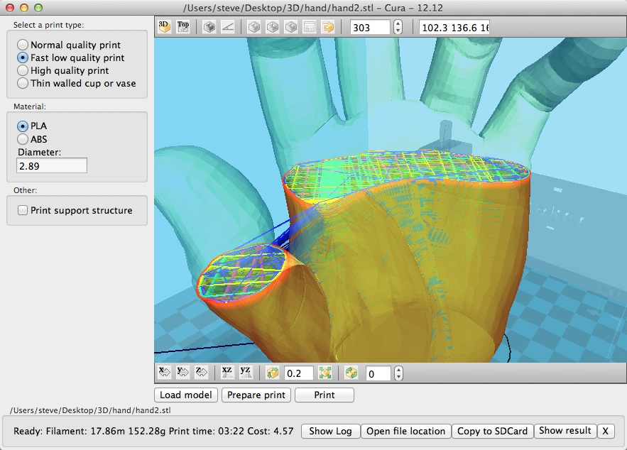
What is pretty difficult though is knowing which slicing / skeining software to use for your 3D printer setup. The skeining software takes your 3 dimensional model in .stl format and slices it vertically in to layers 10ths of a mm thick which the nozzle can then lay down on the build surface.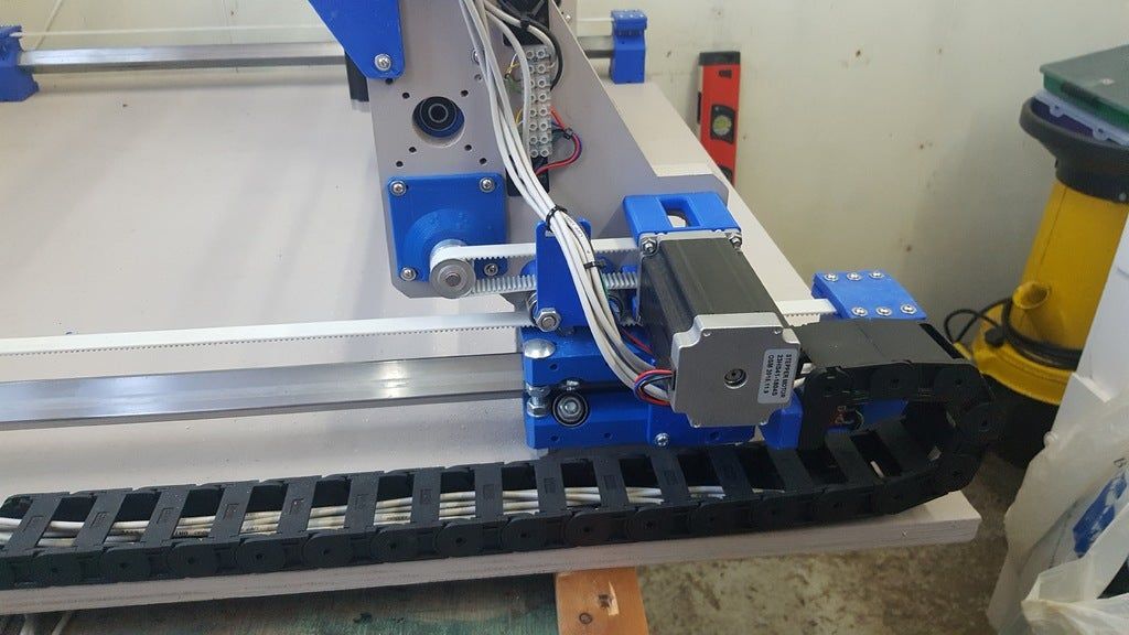 The thickness depends on the size of your extruder nozzle and the quality of print that you need. Some people are printing down to 0.1mm or less with a 0.35mm nozzle.
There are programs such as Slic3r, Skeinforge, Kisslicer and Cura and other packages, or variations of packages, which make using slicing programs such as Skeinforge easier. Most of them are open source projects and freely available for download. I started out using and older version of Slic3r and eventually upgraded to the latest, but I have also tried Kisslicer as well. In some situations Kisslicer works out better and had a better preview, but I find myself going back to Slic3r when the gCode isn’t generated properly in Kisslicer. Sometimes Slic3r doesn’t generate the code properly either, which gets annoying.
In my next post at the end of this week (Week of Jan 21, 2013) I’ll write more about the setup for the 3D Printer. It’s late and I need to wrap this up for now. If you’re looking to Convert a CNC Router to a 3D Printer it certainly is possible, and I have photos to prove it, but I still have a long way to go in the tuning department.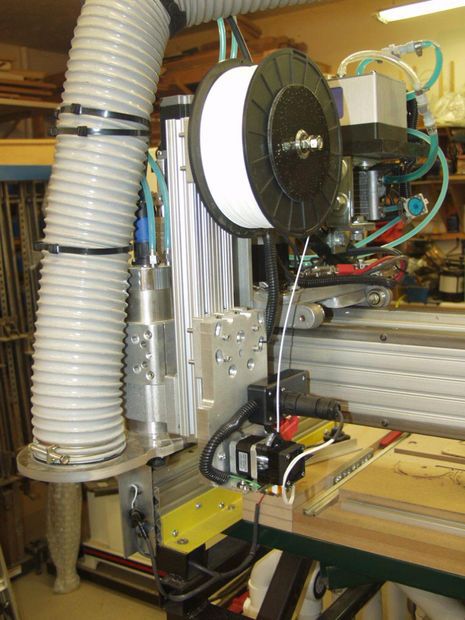
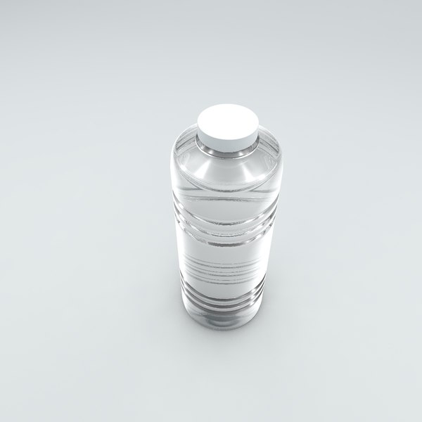
For now here’s the biggest thing I’ve printed so far and a quick video as well! All of my prints so far have been at a 0.2mm layer height with PLA on a 0.35mm nozzle with extruder temperature varying from 180-220 and with and without additional fan cooling.
Tags: 3D Printing, CNC to 3D, HaD Featured, Technology
3D printing or CNC machining
Accelerate product development, reduce costs with a digital manufacturing platform.
Get an instant quote
Upload to production in 5 min.
CNC milling technology has been around since the 1950s and is essentially the opposite of 3D printing. In the case of 3D printing, the computer controls the printer's print head, which "adds" material in three dimensions, with CNC machining, the milling tool is controlled, which removes material.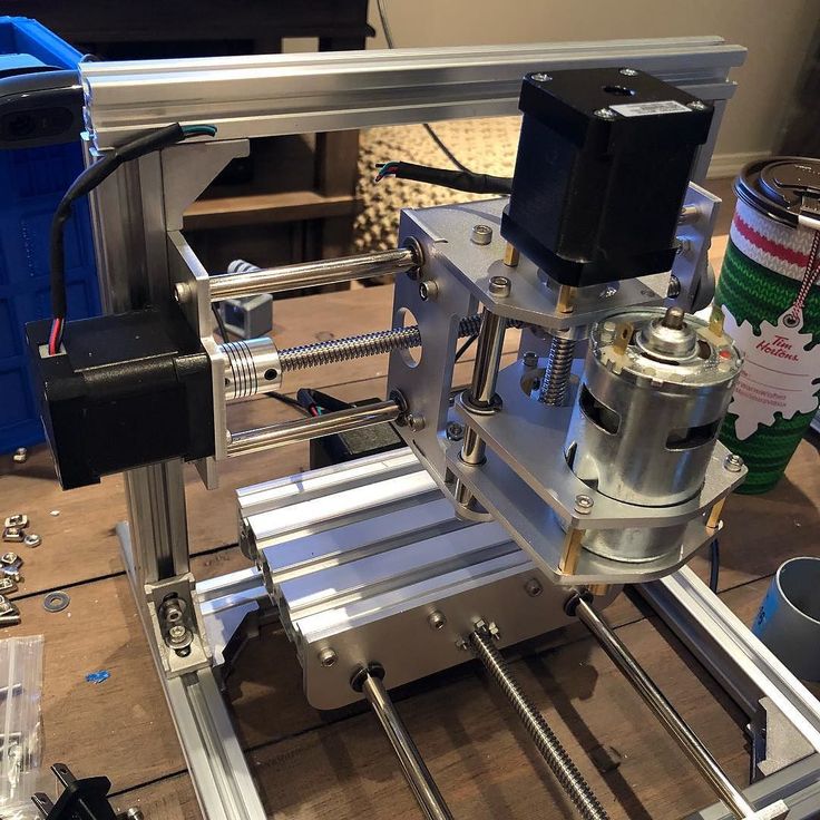 The key difference between the two technologies lies in the way the given geometry is formed.
Designing 3D models for CNC machines and 3D printers is often carried out on the same software, but already at the next stage of preparing the output data, completely different transformation methods are used. So, for CNC processing, a solid model is used, formed by three-dimensional elements - bodies, and for 3D printing, a surface model - consisting of polygons or a shell.
While 3D printing may seem like an evolving and underdeveloped technology, new printers continue to appear in factories as alternatives to CNC machines. Many companies, getting acquainted with 3D printing, are faced with the complexity of the new technology, but continue to look for ways and areas to apply it in their business.
Miscellaneous
CNC milling machines and 3D printers have different technological capabilities and limitations that allow them to solve different problems.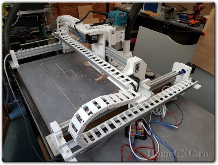
CNC milling machine allows you to efficiently produce large, heavy and high-precision products in large runs, which can be used for the production of commercial and industrial equipment, machines, engines. CNC technology also allows the production of small batches of products, but usually with a higher unit cost.
The flexibility of 3D printing makes it possible to quickly switch between different products. However, since the unit cost of a product is always the same, regardless of quantity, 3D printing is not economically viable for large print runs.
The adaptability of 3D printing makes it useful for creating unique, personalized designs, such as custom trauma or dental implants.
Technology selection
When choosing between CNC and 3D printing, there are a few simple guidelines that can be applied to your decision making process.
Choose 3D printing if:
• traditional methods do not allow the production of a part, for example, for very complex geometries
• production time is critical, printed parts can be produced within 24 hours
• low cost for small runs, number of identical parts (less than 10)
• materials that are difficult to process, but it is possible to print, such as alloys of certain metals
CNC machining:
• offers high accuracy and uniformity of mechanical properties throughout the volume of the product (isotropy, as opposed to anisotropic properties in printed products), but usually comes at a higher cost, especially for small volumes
• stability of time costs and the result with a proven technological process
In this case, the key factor is the total number of products - circulation.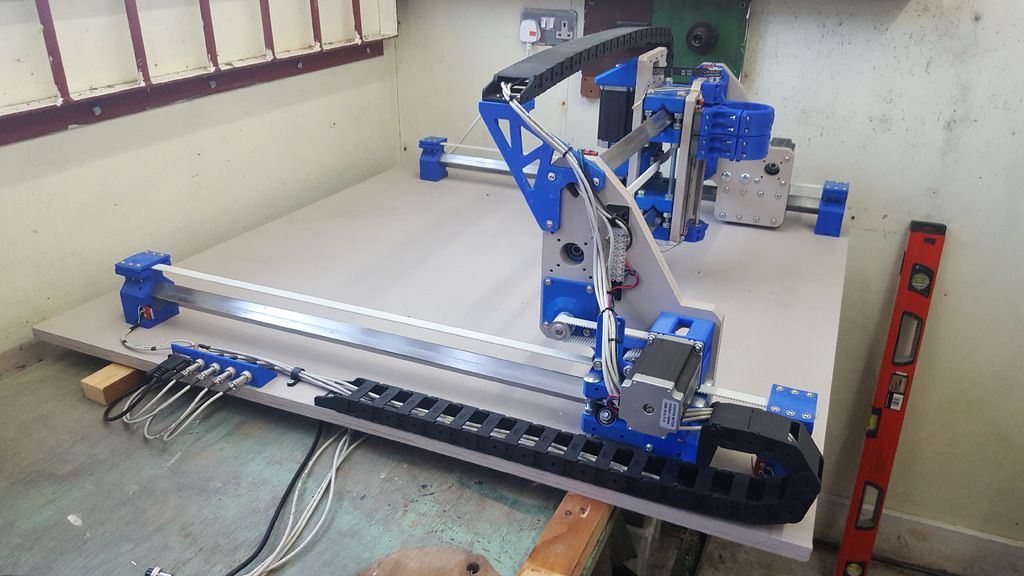 And if mass production of items (hundreds or more) is required, then neither CNC nor 3D printing can be a cost-effective option. Traditional molding techniques such as investment casting or injection molding will be the best choice.
Materials
CNC machining is mainly applied to the processing of metals and modeling plastics:
• Plastics: ABS, nylon, polycarbonate, PEEK
• Metals: aluminium, stainless steel, titanium, brass
3D printing predominantly works with plastics and, to a lesser extent, with metals:
• Plastics: Nylon, PLA, ABS, ULTEM, ASA, TPU
• Metals: titanium, stainless steel, cobalt-chromium alloys
Product geometry complexity
CNC
There are a number of constraints to consider when designing CNC parts, including tool access and tolerances. A feature of CNC machining is the internal corners of the product, which always have a radius due to the shape of the cutting tool, but the outer surfaces can have sharp edges.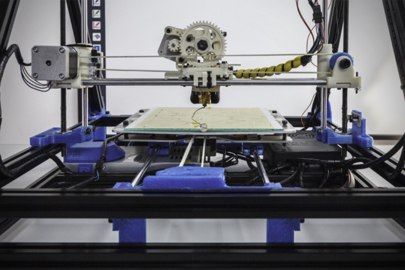 Also, most non-standard geometries require rotation of the part to access different sides. Rearranging the workpiece increases the processing time, non-standard fixtures and additional fasteners may also be required, which together affect the final cost of the product. Read design guidelines for CNC machining.
3D print
The ability to create very complex geometries is one of the key benefits of 3D printing. The technology has fewer restrictions, but it should take into account the possible wall thickness of the part, overall dimensions, as well as the need to build support for most types of printing.
Manufacturing process
CNC
The main difference between the CNC machining process is that after the CAD file is received for production, the technologist or engineer works out the choice of tool, processing speed, tool path and changing the position of the part. All these factors greatly influence the quality of the final part and the working time.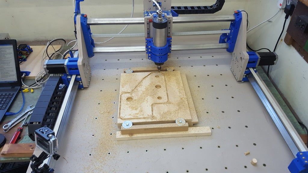 That is, the preparation process is time-consuming, and the production itself in most cases requires the presence of an operator.
3D printing
In 3D printing, the printer operator prepares the orientation of the model in the printer and adds support, and then sends the file to the printer, where it is printed without additional involvement of a specialist.
Post-processing
Also, parts both after machining and 3D printing can be applied a number of post-processing methods that improve the functionality and appearance of the product:
• blasting
• heat treatment
• anodizing
• painting, powder coating
• grinding and polishing
For printed products, post-processing can be additionally carried out on CNC machines to improve the accuracy and quality of the surface, parts are made with a built-in allowance, after which the material is removed mechanically.
Terminals
To a certain extent, CNC and 3D printing technologies overlap in their capabilities, but each of them has its own strengths and weaknesses that make them suitable for solving specific problems.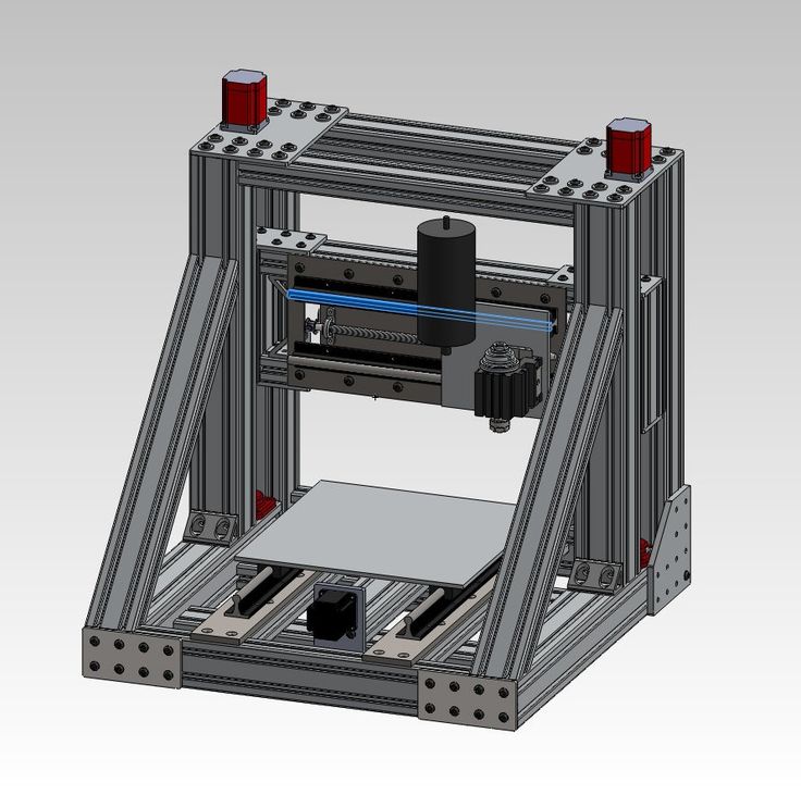
CNC milling machines are usually best suited for projects that require complex, high-precision parts with a production run of 100 to 1,000 pieces. 3D printing is ideal for prototyping and personalized, customized products.
Compare also:
Polyurethane injection molding vs injection molding
3D printing technologies
Types and properties of polyurethane
3D printer from desktop CNC router
- home
- Articles
- It is interesting
- 3D printer from a desktop CNC milling machine
Installing a 3D printer print head on a desktop CNC, expands the possibilities of using a milling machine.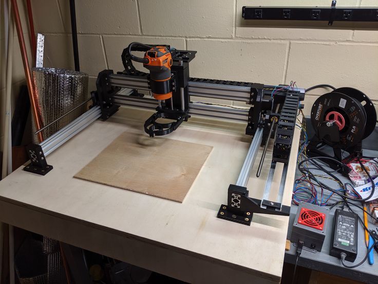 Process control is also possible using the MACh4 program, widely known in the CNC environment. 3D printing requires an STL file, which is supported by all 3D printer software. To convert to STL, you can use Soildworks, google Sketchup and other programs.
For 3D printing on a desktop CNC machine, we use a 3D printer extruder, having previously replaced the temperature sensor with a type K thermocouple, or purchase it in our store
2. To mount the spool of 3D printing filament, we assemble the rack from an aluminum profile
3. Fix the rack with the spool of 3D printing filament on the desktop CNC machine
4. Install additional software.
4.1 From http://cnc2printer3d.wordpress.com/software/ download Mach4 Addon conversion version 1.2, file setup1.2.exe.
Mach4 Addon installation package contains Skeinforge software, needed to be able to convert 3D files to G-code.
4.2 Download and install python language support https://www.