Ciclop 3d scanner firmware
Ciclop based Laser Scanner — FabScanPi documentation
1. About Ciclop
2. Bill of Materials
The following list shows what you need to modify the Ciclop scanner for using the FabScanPi Software.
General components
- 12V to 5V switching regulator
- Raspberry Pi 3 B+ or higher
- Raspberry Pi camera V2
- Raspberry Pi Camera Connection Cable - 50cm
- Micro SD Card ( >= 8GB)
- Silent Step Stick Motor driver
- 3D printed Camera Mount
- 3D printed Raspberry Pi Mount
3. Ciclop Modification
Mounting Raspberry Camera
You can use a printed camera mount to mount the Raspberry Pi Camera to the ciclop. The Raspberry Pi Camera will replace the USB webcam.
Note
The Raspberry Pi camera has a better image quality than the ciclop USB webcam.
Replacing the Motor driver
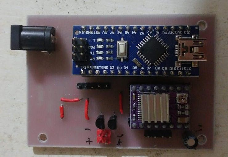
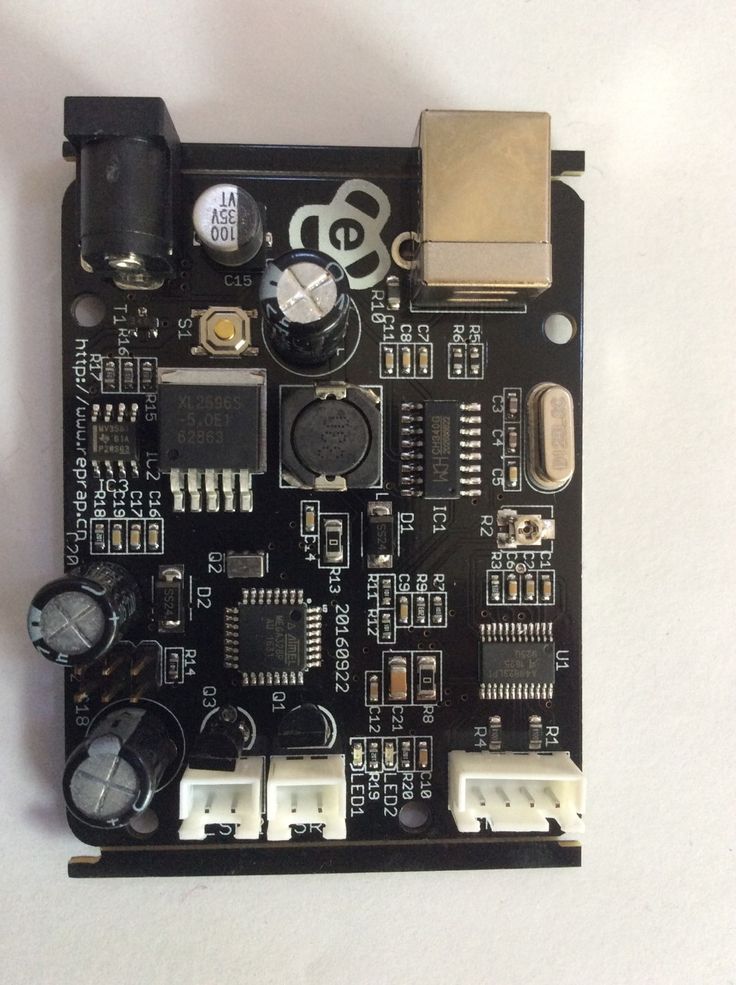
It is recommended to replace the default motor driver of the ciclop with a silent step stick driver. You can use a TMC2100, TMC2208 or TMC2009. But you need to configure the TMC2xxx driver to run in 1/16 micro stepping mode. If you decided to use the TMC2100 driver all you need to do is removing the jumpers under the ciclop motor driver. For other TMC drivers read the manual at watterotts TMC guide.
The motor driver which was included in the kit has a red or green surface.
The picture shows a TMC2100 motor driver on the ciclop Arduino Shield.
Note
You can also use the default driver, but the usage of a TMC motor driver lets the turntable move much more silent and smooth. That leads you to much better calibration and scan results.
Connecting Raspberry Pi
Connect the Ciclop Arduino USB cable to the USB port of the Raspberry Pi. Then connect the Raspberry Pi camera ribbon cable to the Raspberry Pi.
Note
You can use a Raspberry Pi camera ribbon cable extension (50 cm).
You can use a Ethernet cable for Network connection or configure the Raspberry Pi’s wifi setting-up-wifi.
Warning
The Raspberry Pi 4 needs active cooling by a fan. Otherwise the scan process will stuck or fail.
Proceed with the Power Management.
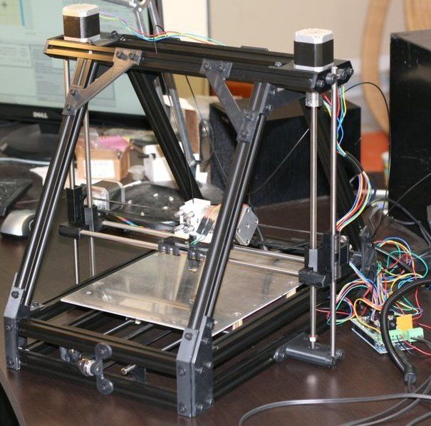
The Power Management
The fastest way is using two power supplies. One 5V supply for the Raspbbery Pi and a second one with 12V connected to the Arduino for the motors.
Warning
Do not use the 5V supplied by the Arduino, because it does not supply enough current. The Arduino and even the Raspberry Pi may be demaged otherwise.
But if you want a setup with less wires, you should add a Step-Down converter like on the picture below.
The 5V output of the Step-Down converter is connected to the 5V and GND pin of the Raspberry Pi.
Connecting LEDs (WS2812)
It is recommended to connect a WS2812 LED-Ring or some WS2812 LED stripes for a better illumination of the object. You can use the 6 pin header on the original ciclop ZUM board.
5. Software Installation
Now you need to install the FabScan sotware.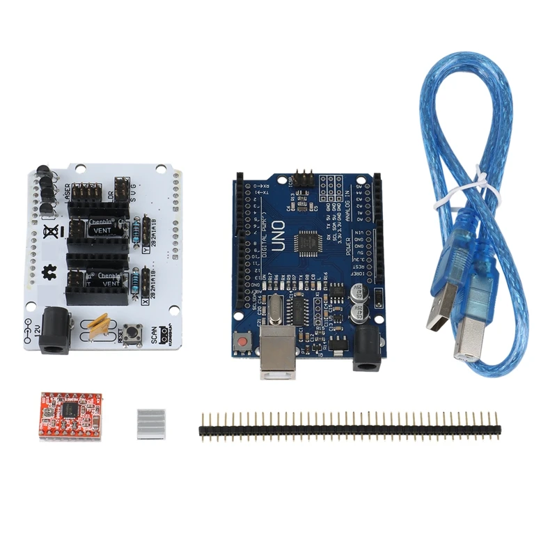 Please follow the Guide for Installing the Software.
6. Software Configuration
The image installation from the previous step already contains a default configuration for the FabScan. But some values need to be adjusted, depending on your hardware setup. You should recap your motor type, and the number of lasers at this point.
Note
If you don’t know how to edit a file by using a text editor on a Raspberry Pi console, you should read detailed chapter on How to Edit the Config File first..
Motor Config
You should be sure that the number of steps matches your motor. If you are using a NEMA17 motor, the common number of steps for a full revolution is 200 (1.8 degree per step). The motor driver is set to 1/16 step what results in 16*200=3200 steps. Most of the ciclop kits come with a 200 steps stepper motor.
Warning
It is important to set a correct value for your motor. A incorrect value can cause double/mirrored looking scans results.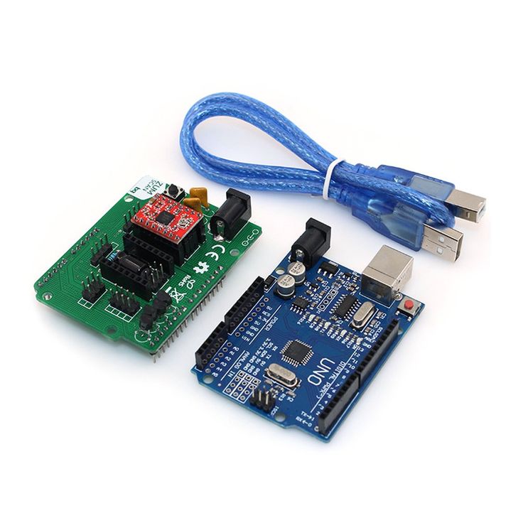 Even the calibration process might fail.
The example below shows a configuration for a 200 step stepper motor. The cilop turntable radius is 100mm. If you are using another turntable than the default one, change the radius.
"turntable": { "steps": 3200 "radius": 100, "height": 155 } Laser Config
Change the number of lasers to a number which matches your setup. If you are using just one laser then change numbers to 1, otherwise numbers should be 2. And be sure that interleaved is set to true.
"laser": { "interleaved": "True", "numbers": 2, "color": "R (RGB)" } Serial Connection
Be sure that the connector type is serial and the firmware is set to ciclop. The port should match the serial port where the ciclop board is connected. Mostly the port is /dev/ttyUSB0. The baudrate should be set to 14400 for the ciclop.
"connector": { "type": "serial", "firmware": "ciclop", "baudrate": 14400, "autoflash": "True", "port": "/dev/ttyUSB0", "flash_baudrate": 115200 } Calibration config
You need to change the calibration board config to the ciclop calibration board values.
"pattern": { "square_size": 13, "rows": 6, "columns": 10, "origin_distance": 35 }, Note
Read more about the calibration configuration in the advanced Advanced Configurations section.
Leave the rest of the file as it is.
7. Using the Software
You can proceed with the software First Steps with the Software . A more complete software manual can be found in the section Software User Manual. Don’t miss to read the section about Calibrating the Software.
Note
A precise calibration is the key for good scan results!
production and assembly of the control PCB – 2 – Renzo Mischianti
Spread the love
Support forum
In this article I would like to show my custom PCB for the Ciclop 3D scanner which is fully compatible with the original ZUM.
Ciclop 3D scanner electronic PCB solderingI made my own PCB to replace the original ZUM SCAN one (bigger and more expensive). I also share it on PCBWay.
Ciclop 3D scanner board v1.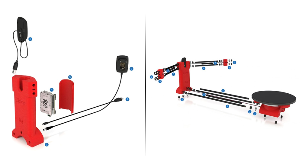 2 PCBWay
PCB v1.0
This is a fully functional version (videos are made with this version) and it was the simplest. In version v1.2 I thought about adding a resettable PTC to avoid burning the engine (it never happens usually), I made my version with an old Epson Stylus Color 460 stepper motor.
I wrote a guide on how to reuse the old stepper motor “How to reuse 4 and 6 wires stepper motors for your projects“
As I said, the PCB is fully compatible with the original one. Zum scan is more complex, but all additional features is unused.
Ciclop 3D scanner board v1.0 schemaMy version is for Arduino Nano, so It’s more little than the original one.
PCB Etching
I never used this technic, but I add to this step the svg file or PDF for production.
Ciclop 3D scanner etchingDownload
Milling PCB
I use this technic for my personal production, I think you can find interesting this series of articles “Cyclone PCB factory: how to build It” and “Milling PCB tutorial“.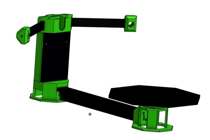
Milling PCB: the Milling Process
First mill the copper bottom, then drill the holes.
Here the first traces pass.
And the finished work.
Milling PCB: clean the milled PCB
Than use sand paper to made the board flat and clean. This is my first version, in the next paragraph I add the updated version.
PCB v1.2
As I said, I later created a PTC resettable fuse board, (1.85A 30V) this simple component protects your stepper from the current problem. This card is fully compatible with the original one.
Ciclop 3D scanner board v1.2 schemaSo to test the board I restart the whole milling process and here is the result
Ciclop 3D scanner board v1.2 milledCiclop 3D scanner board v1.2 milled sunHere the new board active and mounted.
Ciclop 3D scanner new board v1.2 with resettable fuse at workOrder 10 PCBs for 5$ on PCBWay
You can order the PCB at PCBWay for few dollars here
Ciclop 3D scanner board v1.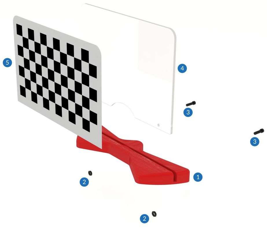 2 PCBWay
PCB Assembly
Complete BOM
Here is the list of components.
| 2 | 1kΩ Resistor |
| 1 | 100µF Electrolytic Capacitor |
| 1 | DRV 8825 (with one divider jumper) or a4988 Stepper Motor Carrier |
| 2 | Generic female header – 15 pins |
| 2 | Generic female header – 8 pins |
| 1 | Generic male header – 4 pins |
| 2 | Generic male header – 3 pins |
| 1 | Barrel 5.5 power Jack (breadboard friendly) |
| 1 | Generic female header – 5 pins |
| 2 | Red (633nm) LED |
| 1 | Arduino Nano (Rev3.0) |
| 1 | 1.85A 30V Resettable Fuse PTC (Not needed on v1.0 board) |
| 2 | NPN-Transistor 2n2222a |
| 1 | 10kΩ Resistor |
And here the links to the less common components
- Arduino Nano
You can find It here AliExpress
- A4988 Stepper driver
You can find It here AliExpress
- 2x 1k resistor
- 1x 10k resistor
- 2x 2n2222 transistor
You can find It here AliExpress
- 5.
 5 Barrel for input voltage
Barrel Jack breadboard friendly on Aliexpress Breadboard friendly 5.5x2.1 - Aliexpress 5.5x2.1
- In the new board you need only one more component the PTC Resettable fuse 30v 1.85A
You can find It here AliExpress
Solder the components on the milled PCB
Now we add the components to the board after the assembly process.
Here the PCB from PCBWay.
Ciclop 3D scanner PCB descriptionAnd here the result.
And here the finished PCB with compoents.
Ciclop 3D scanner PCB v12 with componentsNow we must start to add all electronic cable, I explain how to in the next article.
I use 12v 2A power supply (to the barrel) to power a stepper driver.
Ciclop 3D scanner board installedThe USB connector is sufficient for laser and Arduino, but the power supply is for the stepper.
Thanks
- Ciclop 3D scanner: component printing and assembly
- Ciclop 3D scanner: production and assembly of the control PCB
- Ciclop 3D scanner: assembling electronic and wiring
- Ciclop 3D scanner: componens testing and calibration
Support forum
Spread the love
Ciclop 3D scanner - the devil is in the details!
Iro4ka
Loading
05/04/2015
40451
Reviews
In this article I will try to answer most of the questions received in PM on assembling the scanner.
Firstly, the scheme is very simple. Whoever is in the subject will immediately understand everything! ;)
Hex firmware and programmer in one archive https://yadi.sk/d/Osx0nHOTgQTmR. This programmer works directly through USB Arduino.
Board layout in layout5 https://yadi.sk/d/TSrsSwFGgLJz2 .
If you decide to print body parts on a printer, it is better to cut the webcam mound into three parts https://yadi.sk/d/O1D0PyyJgQTti . But you can also cut out the body parts from plywood and also connect them with M8 studs. And you can assemble a scanner from anything at all. Its main dimensions are the distance from the camera to the center of the table 310-315 mm, the ears for lasers are set at an angle of 30 degrees. to the camera plane, their length is 15 cm from the center of the camera to the lasers. If the lasers are installed on the same plane as the camera, the distance between the lasers should be 200+200=400 mm.
Chinese lasers with a focusable lens should be adjusted to project the thinnest line and the focusing thread sealed with instant glue (cyacrine). Otherwise, the calibration of lasers can be lost from the slightest shock, as these lenses hang on the thread in the laser body.
Calibration must be done strictly in order, including camera calibration with different positions of the calibration chess field in space. It is better to calibrate the lasers several times and choose the closest repeating values.
That's pretty much all you need to get started with the Ciclop 3D scanner for the first time. :)
Subscribe to the author
Subscribe
Don't want
42
Article comments
More interesting articles
D!al Up
Loading
10/17/2022
4836
37
Subscribe to the author
Subscribe
Don't want to
Hello everyone.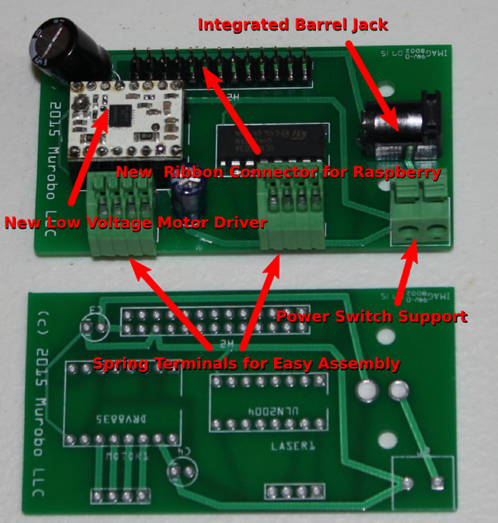 The photo in the header is for those who start talking about the frivolity of my...
Read more
Fox
Loading
07.10.2022
3024
23
Subscribe to the author
Subscribe
Don't want
A long time ago, you can say in another life, I got excited about buying a photopolymer printer. From one...
Read more
nk.xcfg
Loading
05/10/2016
38282
117
Follow author
Follow
Don't want
“A good tester won't even launch the app.” (heard at work) Based on real...
Read more
Ciclop 3D scanner.
 With my own hands.
 Ciclop 3D Scanner by bqLabs
http://www.bq.com/gb/products/ciclop.html
http://diwo.bq.com/en/ciclop-released-2/
Firmware code https://github.com/bq/ horus-fw
Firmware HEX http://diwo.bq.com/en/horus-fw-released/
Firmware Hex Fill http://russemotto.com/xloader/
Cyclops Building Experience "Ciclop 3D Scanner - Devil in the details!"
Discussion of my research on TriDeshnik http://3deshnik.ru/forum/viewtopic.php?f=8&t=15
What do I need to build
Cleaned it from supports. You can download a blank part. While I will cut into three parts for twisting with screws.
Cut into three parts for twisting with M3x10 screws. Download archive with stl models.
General connection diagram of the stepping engine driver
Connection to Arduino Nano
Laser We Connect D2+GND, D3+GND
9000 9000 9000 9000
111 Table assembly
3 - M3x10 screw 5 pieces
4 - M3 nut 1 piece
6 - M8x30 bolt 3 pieces. Screwed into the disc (10). You can take the M8 screw "in the secret" and screw it in from top to bottom, tightening it with a nut at the bottom.
LASERS installation and fixation
2 - m3x10 Washing screw of laser housing, 2 pcs
3 - m3 Gaika 2 pieces
4 - laser 2 pieces Association
- M8x400
2 - M8 nut 28 pcs.
3 - M8 washer 18 pcs. Routed between the nut and the plastic part
4 - Cable duct. Can be replaced with electrical tape
5 - M8x292 threaded stud 1 piece
6 - M8x170 threaded stud 4 pieces. Hold lasers. I think it's wiser to put thinner studs here
7 - Cable channels 3 pieces. Can be replaced with electrical tape or heat shrink
Checkerboard pattern holder assembly
2 - M3 nut 2 pcs
3 - M3x10 screw 2 pieces
4 - plywood cardboard
5 - chess paper-sticker. pdf, svg
Assembly video
Until I started assembling it seems to me that this is enough for the assembly.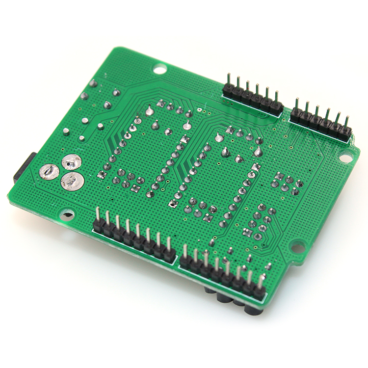 In the course of the infa will change and be supplemented.
Assembly
Brutal bearing0003
As a result, I will have to do it on Arduino Uno, since I miscalculated with Nanami.
I've already stumbled on connectors in UNO;)
We've arrived. Horus does not see UNO's COM port.
And in the device manager, instead of Arduino UNO, it says Ch440. It looks like you have to reflash the bootloader.
Here is the correct scheme for flashing UNO (Duemilanova) via MEGA 2560. Only I have a 100 microfarad conduit (probably will do). I will check.
Arduino UNO bootloader firmware steps ( Duemilanova), via Arduino Mega:
[ Click to read ]
step 1 - Nothing is connected to Mega except USB cable. Launch the Arduino IDE. We set the Mega parameters: Board, Processor, Port.
step 2 - Go to menu File -> Samples and click ArduinoISP.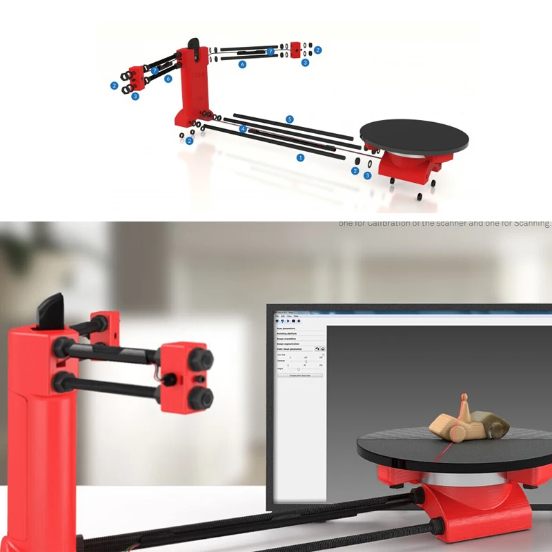 The sketch of the ArduinoISP programmer is loaded into the editor. Press the round button with an arrow to the right "Upload" and upload the sketch to Mega.
step 3 - Disconnect Mega from everything and connect to UNO (Duemilanova) according to the scheme (above). And we also stick a capacitor (I have 100 microfarads). We connect Mega via USB to the computer.
step 4 - Now in the Arduino IDE set the parameters for UNO (Duemilanova): Board, Processor, Port
step 5 - Go to Tools -> Programmer and click on "Arduino as ISP". Now our Mega has become a programmer.
step 5 - Flash bootloader on UNO (Duemilanova) via Mega. In the Tools menu, click "Burn bootloader". Both boards should have blinking LEDs. Ready. We disconnect everything.
I tried to reflash Bootloader according to the scheme in UNO. Everything blinked and flooded, but in the end nothing came of it. Apparently the fuses are wrong.
The Arduino Nano got free and I connected it to the computer.