How to make a 3d printed robot
How to Build Your Own 3D Printed Raspberry Pi Robot (Updated)
Skip to main contentTom's Hardware is supported by its audience. When you purchase through links on our site, we may earn an affiliate commission. Here’s why you can trust us.
(Image credit: Tom's Hardware)Update 7th August 2022: We've updated this article to include how to program the Explora in Python on page 2.
Original Tutorial Published June 4, 2022:
Building your own robot is one of the most satisfying things you can do. It combines mechanical, electrical, and programming skills together in a way few projects do.
I’ve been building robots for a couple of years now and love to expand my knowledge and skills by using different controller boards, motors, wheels, and sensors to detect the world around the robot.
Raspberry Pi robots are particularly impressive. The Raspberry Pi provides the robot with the full power of Linux and a plethora of Python libraries. With all of this power, it means we can add advanced machine learning, computer vision, and Internet connectivity into the mix. All this at an affordable price point and tiny form factor too.
Building Raspberry Pi robots from kits, such as Pimoroni’s Trilobot, or from a custom design such as Explora, is fun and helps develop skills such as programming in Python, mechanical design, and electronics. People love playing with robots and teaching them to perform tasks and move around the environment unaided.
Explora uses the Pimoroni Explorer pHAT (we included the Explorer HAT Pro in our best Raspberry Pi HATs guide) to control the motors and has a handy Python library to make this simple. Explora is programmed in Python and uses sensors to avoid obstacles and follow your handExplora can also be remotely controlled over Wi-Fi.
Explora can detect objects in front of it using an HC-SR04 ultrasonic range finder module. These modules come in either a 5v version or a 3.3v version (HCSR04+ or HC-SR04P).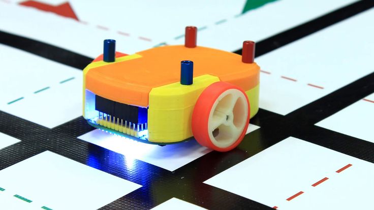 The Explorer pHAT is 5v tolerant, but it's best to get the HC-SR04+ or HC-SR04-P version to be on the safe side. Using the 5v version on a Raspberry Pi can damage the board.
Explora was designed using AutoDesk Fusion 360 . Each piece is a discrete component to enable easier 3D printing. Fusion 360 makes it really easy to export the models into STL files, ready for slicing and then 3D printing. To slice the robot parts (creating the instructions for a 3D printer to print the part) from Fusion 360 I use Cura, and then upload it to OctoPrint to manage the print jobs. The 3D printed parts are designed to be quick and easy to print, and the whole thing is easy to assemble using a couple of screws and wire up.
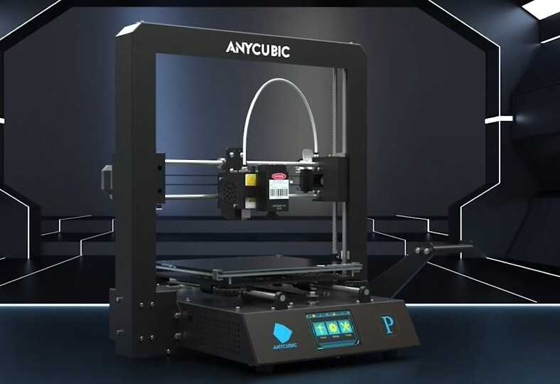
My personal choice of 3D printer is the Creality Ender 3 Pro and Ender 3 V2.
The electronics for the project are relatively straightforward and involve some soldering. You will need to solder wires to each motor and then to some Male DuPont cables (jumper jerky), one set per motor.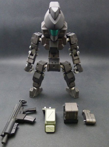 You’ll also need something to hold the motors while you solder the wires to the tiny motor connectors which can be a bit tricky if you’ve not done this before. Some “helpful hands” or modeling clay is useful to keep the wires in place.
What You Will Need
- A 3D printer and filament
- 8 x M3 10mm screws and nuts
- 4 x N20 Motors
- 1 x Pimoroni Explorer Hat
- 1 x Raspberry Pi Zero 2 W / Raspberry Pi Zero W
- USB Powerbank battery pack
- 400mm of red wire - solid core is preferable over the braided wire
- 400mm of black wire - solid core is preferable over the braided wire
- 8 x M2.5 Stand-offs (with male screw)
- 4 x M2.5 Stand-offs (without male screw)
- 8 x M2.5 Screws
- 4 x Moon buggy wheels
- 4 x Male to female Dupont cables (200mm)
- Some velcro straps for the battery pack
- SD Card for the Raspberry Pi Zero
- PIR Obstacle sensor
Tools
- Soldering iron
- Solder and some flux
- Screwdriver
- Wire cutters
- Wire strippers
- Helping hands - for use with soldering
- A computer with an SD card reader slot
3D Printed Files
- 1x Chassis
- 4x Motor holders
- 1x Camera Holder
- 1x Camera back
- 1x Top section
Building Explora
(Image credit: Tom's Hardware)The print times for each of Explora’s parts depends on your specific printer and quality settings. I found the files took the following amount of time to print:
| # | Part | Approx Time to Print |
|---|---|---|
| 1. | Chassis | 5 hours 16 minutes |
| 2. | Top Section | 2 hours 22 minutes |
| 3. | Motor Holders - all 4 at once | 3 hours 44 minutes |
| 4. | Camera holder & Camera holder back at once | 2 hours 30 minutes |
I prefer to use PLA+ for my prints and usually have some white or yellow filament already in each printer, ready to go.
To Prepare Explora’s 3D Printed Parts
(Image credit: Tom's Hardware)1. Download the 3D printable STL files.
2. Slice the parts using Cura - We like to use Cura, but you are free to use an alternative. and don't forget to enable supports for the motor holders
3. Transfer the G-Code file from Cura to your 3D Printer. Save the G-Code file to an SD card (if that's how your 3D printer accepts files) alternatively you can use software such as OctoPrint that runs on a Raspberry Pi and presents a Web-based interface for managing 3D Print jobs. If you’re using OctoPrint you can drag the G-Code file over the left-hand side of the page and it will begin to upload the file, ready for printing.
4. Load the G-code and print - We used Octoprint to manage our print jobs
Wiring up Explora
(Image credit: Tom's Hardware)Soldering is an essential maker skill. Learning to solder opens up the entire world of electronics and this project could be your first steps on an exciting journey. If your motors come without any wires attached you’ll need to prepare your own wires and solder these onto the tiny motors. Soldering small parts can be tricky; you will need a steady hand and something to hold the motors while you hold the solder in one hand and the soldering iron in the other.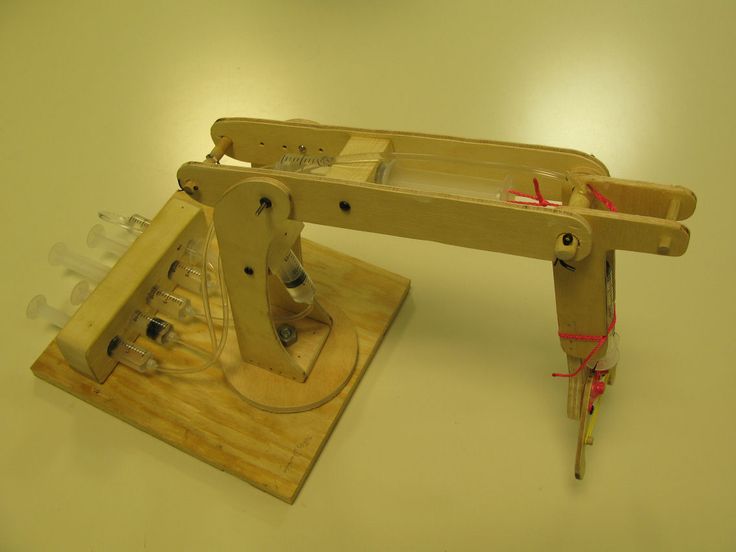
- Prepare the wires for soldering. Cut four strips of red wire 100mm long each and another four strips of black wire. We should have a pair of black and red wires for each motor.
- Strip wires. Strip about 4mm of wire from each end, exposing the copper wire. A good pair of wire strippers is an essential part of a maker's toolbox.
- Add Flux. Apply some flux to one end of the wire that will be soldered. Flux helps the solder run around the part correctly. Even if your solder comes with a flux core, a little extra flux will make soldering much easier.
- Tin the wires by adding a small amount of solder to the wires with your soldering iron. Tinning will help the wires solder to the small motor terminals
- Solder the red wire onto the motor terminal - you’ll notice a small + sign above the terminal that is the positive terminal. Take your time, as this can be tricky if you’ve not done it before.
- Push the wire through the hole in the terminal first to make a good mechanical connection and will help hold the wire in place as you solder, then solder the wire to the terminal.
- Repeat the last step for the black wire but this time solder the black wire to the Negative terminal on the motor.
- Twist red and black wires for strength. This will help strengthen the connection if you accidentally tug on the wires.
9. Solder the 40 pin header and 20 pin header to the Explorer pHat
(Image credit: Tom's Hardware)Assembly
The assembly part of the build won’t take long as it only involves screwing the four motor holders into the chassis using the M2.5 screw and nuts. Then we screw the standoffs into the chassis and Raspberry Pi Zero 2 W, and finally, we attach the Camera holders and top section.
1. Push each motor into a 3D printed motor holder. The motor holders ensure that the motor remains in place on Explora’s chassis. They also offer mechanical rigidity so that the motors do not move position in use.
2. Put a nut into each hexagonal pocket on the motor holder, then screw it from the top side of the chassis through to the motor holder into the nut. Don’t over-tighten as you’ll end up splitting the chassis. This will create a substantial connection between the motor holder and the chassis.
(Image credit: Tom's Hardware)3. Add stand-offs to the chassis by screwing four M2.5 screws into the bottom of the chassis, and screw on a stand-off barrel onto the exposed screw thread until it becomes tight against the chassis.
4. Add four stand-offs to the Raspberry Pi Zero, then attach the Explorer pHat.
(Image credit: Tom's Hardware)5. Screw the Raspberry Pi Zero into the Chassis stand-offs.
6. Push the Camera Holder into the Chassis. You may need to file off some material if it's a tight fit.
7. Push the ultrasonic rangefinder into the Camera Holder.
8. Push the female end of the DuPont wires onto the Rangefinder.
9. Push the male end of the DuPont wires onto Explorer pHATs 5v, GND, Output 1 to Trigger, Input 1 to Echo connections.
10. Push the Camera back into the Chassis.
(Image credit: Tom's Hardware)11. Add the last four stand-offs onto the Raspberry Pi Zero
12. Push the Top section over the two camera holders and screw the last 4 M2.5 screws from the top section into the standoffs
13. Using a velcro strap, secure the battery in place.
(Image credit: Tom's Hardware)14. Push the 4 wheels onto the ends of the motors. The motor axles are D-shaped, be sure to match the alignment of the axle to the wheel before firmly pushing on.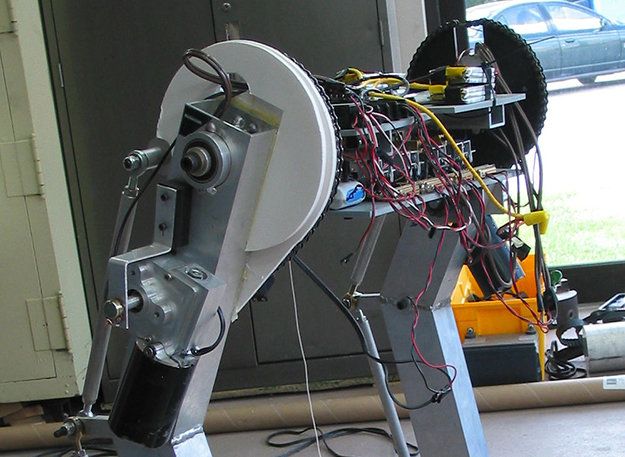
Preparing the Raspberry Pi
The Raspberry Pi needs a suitable OS to run the Python code to control the motors and optionally capture images. When the Raspberry Pi camera first launched a software library called PiCamera was provided to make it simple to capture stills and video. With the most recent release of Raspberry Pi OS ‘Bullseye’, this old library has been replaced with a library called LibCamera, which is not backward compatible with PiCamera. On the 32-bit release of Bullseye you can choose a legacy camera option from raspi-config, however, this option is not available on the 64bit release.
1. Using the official Raspberry Pi Imager tool, flash the latest 32-bit OS to a micro SD card. We use the 32-bit version of Raspberry Pi OS because the PiCamera library is currently not compatible with the 64-bit version of Raspberry Pi OS.
(Image credit: Tom's Hardware)2. Put the micro SD card into the SD card reader slot on your computer.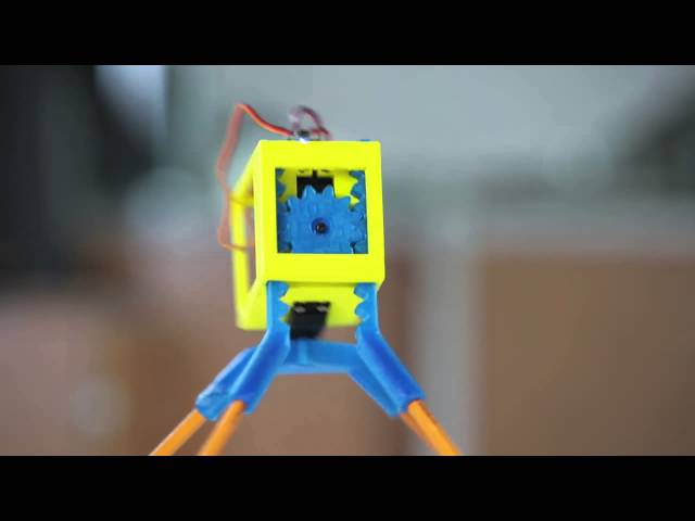
3. Select the micro SD card from the Raspberry Pi imager Storage menu.
(Image credit: Tom's Hardware)4. Click the Advanced (cog) button, and add your Wi-Fi SSID and password details to enable the Raspberry Pi to connect to the wifi automatically.
(Image credit: Tom's Hardware)5. Click on Enable SSH and create a username and password. SSH enables a remote to the Raspberry Pi using a terminal without the need for a monitor, keyboard, or mouse.
6. Click Write to begin flashing the image to the micro SD card.
(Image credit: Tom's Hardware)7. Insert the micro SD card into the Raspberry Pi and then power up the Raspberry Pi via the power bank.
Connecting to the Pi
1. Find out the IP address of your Raspberry Pi - you can usually do this from your router (or wherever your router gets its IP addresses from, or by typing:
ssh pi@raspberrypi.local
- where `pi` is the username you created earlier in step 5 above.
2. Launch Terminal - if you’re on Windows, you’ll need to use some terminal software such as Putty (https://www.putty.org). Mac and Linux computers have terminal build-in.
(Image credit: Tom's Hardware)3. SSH to the Raspberry Pi - Type `ssh [email protected]>` into the terminal to connect to the Pi. Linux / Mac users can use the following to SSH into the Pi. If you know the IP address you cal also type `ssh@<ipaddress>`, where <ipaddress> is the IP address of the Raspberry Pi.
ssh [email protected](Image credit: Tom's Hardware)
From the Raspberry Pi terminal, clone the Explora software repository. The software is on Github, and we can use the git clone command to download the latest version to our Raspberry Pi:
git clone https://www.github.com/kevinmcaleer/explora(Image credit: Tom's Hardware)
4. Install the Explorer Library via Pimoroni’s online install script.
curl https://get.pimoroni.com/explorerhat | bash
4. From the Raspberry Pi terminal, clone the Explora software repository. The software is on Github, and we can use the git clone command to download the latest version to our Raspberry Pi:
curl https://get.pimoroni.com/explorerhat | bash
You should now have a fully assembled Explora robot on your desk, ready to receive your first Explora Python program. You can expand the capabilities of Explora by adding a LIDAR laser scanner and Raspberry Pi Camera such as the ones in the picture below.
Next, we create some programs for Explora in Python to move the robot around and detect objects.
- 1
Current page: Building Explora Robot
Next Page Programming Explora Robot
Topics
Raspberry Pi
Tom's Hardware is part of Future US Inc, an international media group and leading digital publisher. Visit our corporate site .
© Future US, Inc. Full 7th Floor, 130 West 42nd Street, New York, NY 10036.
Top 12 3D-Printed Robots — From Amphibians to Humanoids
Published on August 26, 2021 by Mikahila L.
Robotics brings together all the technologies that make it possible to design autonomous machines; combining knowledge in electronics, mechanics, and even biology. This is a field that has evolved quite a bit since C-3PO first hit the movie screens in Star Wars in1973. Roboticists have been in constant search of innovations that result in greater speed and productivity. Today, we have smarter robots because of advancements in artificial intelligence, machine learning, and of course, additive manufacturing. Indeed, 3D printing is widely used to manufacture robots, whether in the prototyping or final production stage, to imagine structure, materials, and new functionality. This is why we wanted to present to you some of the fascinating 3D printed robots we’ve come across, everything from humanoids, research tools, or even DIY machines—a section that should be of interest to all makers!
DIY Projects
Intel Openbot
Research organization Intel Labs used 3D printing to develop the Openbot, one of the robots that caught our team’s attention the most. The objective of the project was to create a small electric vehicle intended for smartphones, with the motto ‘Transforming smartphones into robots‘. The device is equipped with vast networks of sensors and has powerful computing capabilities allowing it to take advantage of the advanced functionalities of smartphones. Intel experts say they have opted for 3D printing because of its great accessibility, and also thanks to free software that facilitates the development of this type of project.
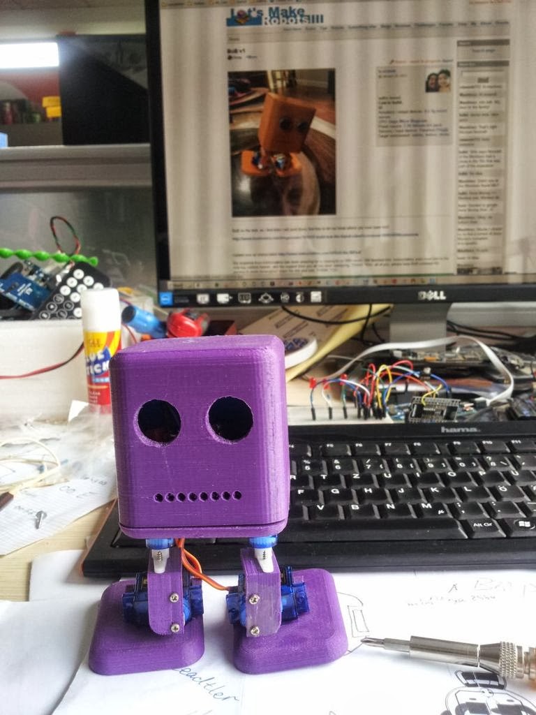
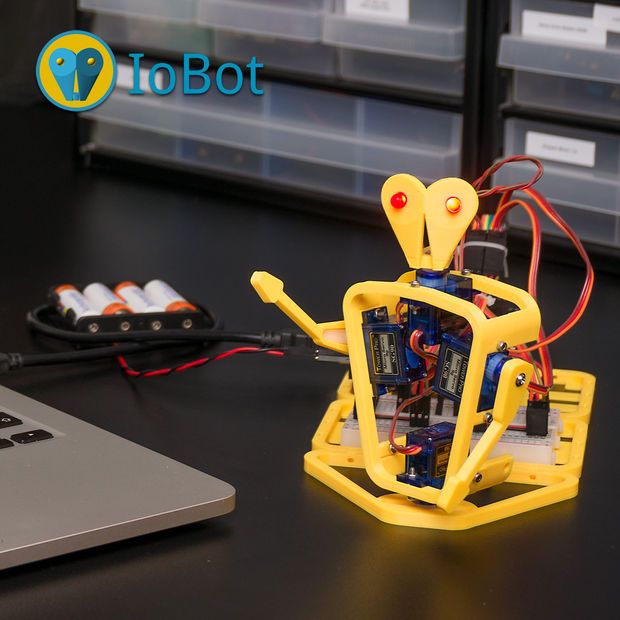
LittleBots is another project that you can do at home with your 3D printer. This robotics kit was created to serve as an introduction to robotics. It features all the necessary components of robotics: sensors, decision-making, and articulation, all in one simple, easy-to-assemble kit. What’s interesting is that LittleBot is fully 3D printed, so it can be made with just 3 screws. The device is open-source and controlled by an Arduino Nano, to take advantage of the global community around it.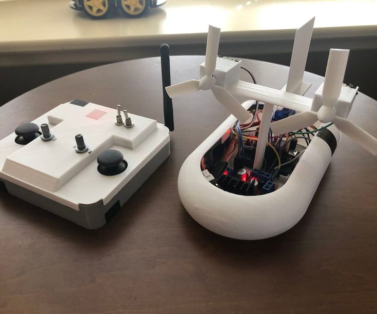 You can find the 3D print files of these robots through Thingiverse; The Arduino code can be found on the LittleBots download page.
Humanoids
Atlas by Boston Dynamics
Boston Dynamics’ Atlas humanoid robots have recently caused quite a stir online with their performance during an obstacle course. Although they have already had some success, Boston Dynamics aims to test the limits of what is possible and continue developing Atlas to make robots withstand extreme conditions. The company relied on 3D printed components for the development of Atlas robots. For example, the legs are 3D printed, which made it possible to integrate hydraulic lines into the structure. Additive manufacturing has also been used to produce custom servo valves.
We could have classified the InMoov robot in the DIY category, as it is an open-source project. Indeed, it is the first human-sized open-source 3D printed robot in the world, created in 2012 by the French Gaël Langevin. Anyone with a 3D printer can therefore design their humanoid robot at home, all you need is a printing area of 120 x 120 x 120 mm. The different parts of the body are printed separately—arms, head, neck, back, shoulder, etc. Everything is meticulously detailed on the dedicated site, whether it is the printing, assembly, and commissioning of this 3D printed robot.
PoppyThe humanoid robot ‘Poppy’ was developed by INRIA Flowers Laboratory in Bordeaux, France. Poppy is open-source and is used by a community of educators, scientists, and artists by sharing hardware, software, and web tools used for a wide variety of visual programming, simulation, and experiments. The robot relies on 3D-printed components made using polyamide material, giving the robot thermal and high-abrasion resistance. Standing at 83 cm tall (32.6 inches) and weighing 3.5 kg (7.7 lbs), Poppy includes a series of electronic components including a 4.2-inch screen and HD camera and costs about €9,039 ($10,610), with less expensive versions available including the Poppy Torso and Ergo Jr.
Jimmy is a 3D printed robot that was developed by the 21st Century Robot company with the goal of getting as many people as possible to build and customize their own robot through 3D printing. Jimmy is made up of custom 3D printed shells that cover his humanoid endoskeleton. Completely open-source, it is powered by an Intel Edison microcomputer, and controlled via WiFi on a smartphone, tablet, or PC using a dedicated application.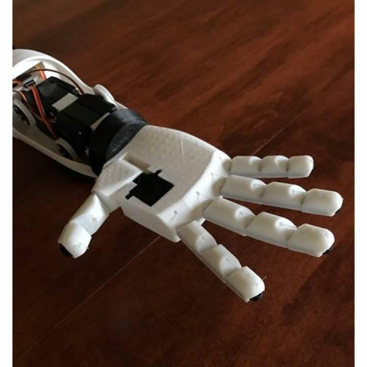
Pollen Robotics Reachy
Another offering from the French company Pollen Robotics (also the creators of Pollen), Reachy is described by the company as an expressive open-source humanoid platform that is programmable with Python and made using 3D printing. Though really just a torso, head, and arms, the main drawing point of this particular robot is not just how expressive it is but also how good it is at interacting with people and manipulating objects. The robot’s maneuverability is to thank for these features. For example, its head is free-moving and it can use antennas to convey emotions. Its two arms have similar dimensions, proportions, and movement as an adult human arm, capable of lifting up to 500 grams. Best of all, the robot is completely customizable and learns thanks to machine learning and AI capabilities.
Research Projects
JSK Laboratory’s Kengoro
Researchers at the JSK laboratory in Tokyo have succeeded in developing a humanoid robot capable of doing push-ups. But playing sports is not Kengoro’s only special feature—its 3D printed metal coating also makes it unique. A well-known problem with humanoid robots is the overheating of motors. In order to better dissipate the heat generated by the 108 engines, the research team opted for an efficient cooling system that can be implemented using SLS 3D printing. The process made it possible to integrate a cooling system into the Kengoro housing and to modify the energy density of the material at various points. This allows water to escape easily and increases Kengoro’s performance. You might even think that the robot sweats during its athletic efforts!
Pleurobot the Amphibious Robot
Pleurobot is a 3D-printed robot that mimics a salamander and was designed by the Ecole Polytechnique de Lausanne in Switzerland. This amphibious robot has practical application for neuroscientists, biomechanists, functional morphologists, and paleontologists as well as roboticists. For instance, Pleurobot will enable research that benefits quadriplegic patients as researchers gain better insights into anatomy and motor skills.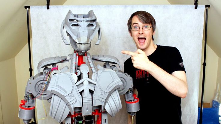 Research may also focus on the evolution of the passage from a swimming animal to one that walks. Swiss engineers also replicated a nervous system using electronic components with a careful scan of a real salamander. Equipped with motors, Pleurobot can swim, crawl and walk like its amphibian counterparts.
‘Astro’, the Intelligent Robodog that Sees and Hears
Scientists at Florida Atlantic University’s Cognitive Robotics and Machine Perception Laboratory (MPCR) have developed Astro, one of the few quadrupedal robots in the world. Unlike many robots, Astro is specified to have a computerized brain inside his head. This one, which looks like that of a Doberman, has been 3D printed. But the commonalities with dogs don’t end with the physical. Astro also has artificial intelligence and machine learning that allows it to learn like a canine.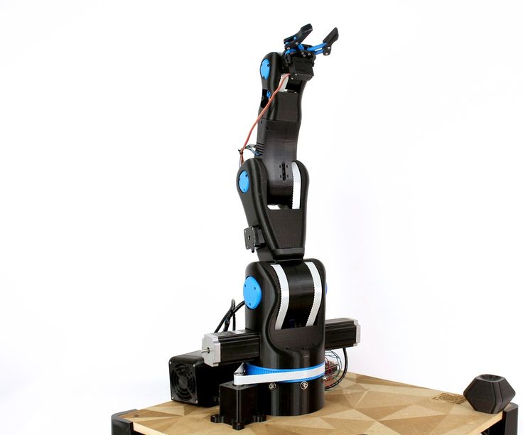 Equipped with sensors, radars, and a microphone, the robotic dog responds to classic commands such as “sit”, “stand” and “lie down”. In some time, Astro will be able to help the police as a scout dog or as a service dog for the visually impaired.
“Micro-Bristle-Bots”
While most of the time human-designed robots are large, this is not always the case. At the Georgia Institute of Technology, researchers have developed microscopic 3D printed robots. Dubbed ‘micro-bristle-bots’, they are barely visible to the naked eye and can be controlled by tiny vibrations. Like ants, microscopic robots work in teams and are able to transport materials. To manufacture the ‘micro-bristle-bots’, the Georgia Tech team used Nanoscribe’s Photonic Professional GT 3D printer, based on the two-photon polymerization (TPP) process. According to the manufacturer, this technology achieves a high level of precision and detail and is ideally suited for micro-printing.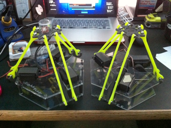
Soft Robots from UC San Diego Jacobs School of Engineering
At the University of California San Diego’s Jacobs School of Engineering, engineers have been working on soft robotics, or the construction of robots from compliant materials, often taking significant inspiration from the movements of living organisms. One such recent project was when researchers designed and tested 3D-printed insect-like robotics. Using FDM and filaments like ABS or PLA, the insects were made using a flexoskeleton process that added rigid features to key components, allowing them to keep their flexibility. This is not the only 3D-printed soft robotics project coming from the school with more expected in the future.
What do you think of our selection of 3D-printed robots? Let us know in a comment below or on our Facebook and Twitter pages. Don’t forget to sign up for our free weekly newsletter, with all the latest news in 3D printing delivered straight to your inbox!
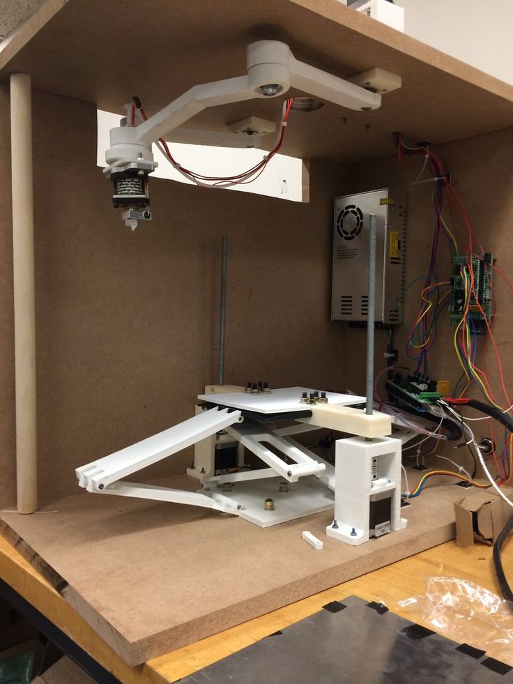
3D printing robot made of plastic and photopolymer resin
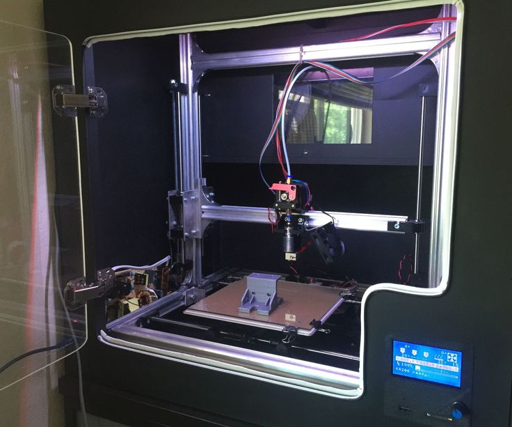
Unusual robot on a 3D printer
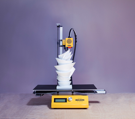
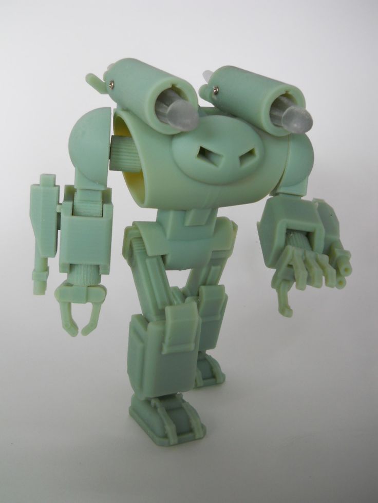
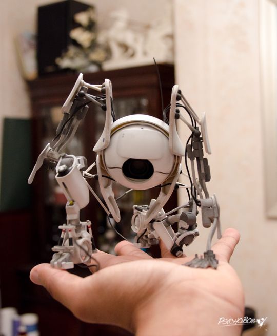
Every day more and more talented designers discover 3D printing technology, with the help of which any, even the most daring, idea gets a chance to become a reality. Inspiration, a little time and diligence - that's all you need to bring your fantasies to life with a 3D printer. Do not hesitate, with the right approach, the result of your work will be simply amazing! The delightful work of Australian artist Paul Braddock, who created a real miracle from 3D plastic and polymer resin, will help to make sure of this - a toy robot with movable limbs. The 3D printing of the robot is so technical that the work done can only be admired.
The designer did a great job on the figurine, and the 3D printing of the robot turned out to be so realistic and spectacular that it would have been enough to take part in some science fiction movie.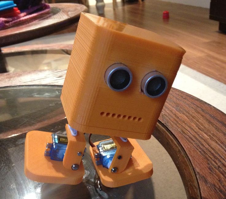 Paul has 15 years of experience as a visual effects specialist, specifically in the fields of conceptual sculpting and digital design. It is quite understandable that these factors made 3D technology especially close to him. The artist closely followed the development of 3D printing, because he immediately realized that it would help him bring creativity to a whole new level.
3D printing in the artist's work
By the way, Braddock is just crazy about a variety of mechanisms - from old cars and motorcycles to all kinds of robots. Thanks to 3D modeling and a 3D printer, his passion was given the opportunity to take on a more concrete form and realize his ideas. Fortunately, Paul has plenty of time to complete projects and he spends it very productively. The artist has a site where he uploads photos of his work.
You can also find various digital models, drawings, jewelry by him and a list of films that Paul has contributed to. There is also a separate section on the site dedicated to 3D printed products.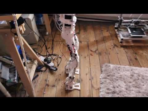 On his blog, Braddock posts detailed descriptions of each stage of the work, which allows newcomers to the field of additive technologies to gain experience and get valuable tips on printing and processing finished products.
3D printing steampunk robot
In the latter, by the way, the artist has been very successful: from time to time he publishes useful tips and tutorials on painting 3D printed samples. For example, last year Paul provided a tutorial on how to create a realistic metal surface effect. As for Robot Eddie (that's what Braddock called the fruit of his labor), it was designed as a gift for the artist's sister, Cassie. She, as a big lover of robots, undoubtedly liked such a present.
As Paul himself explains, he wanted to do something unique and personal for his beloved sister who collects robots. Undoubtedly, the 3D printing robot proved that it succeeded. Now let's talk about creating an exclusive product. The 3D modeling process took the artist about two weeks.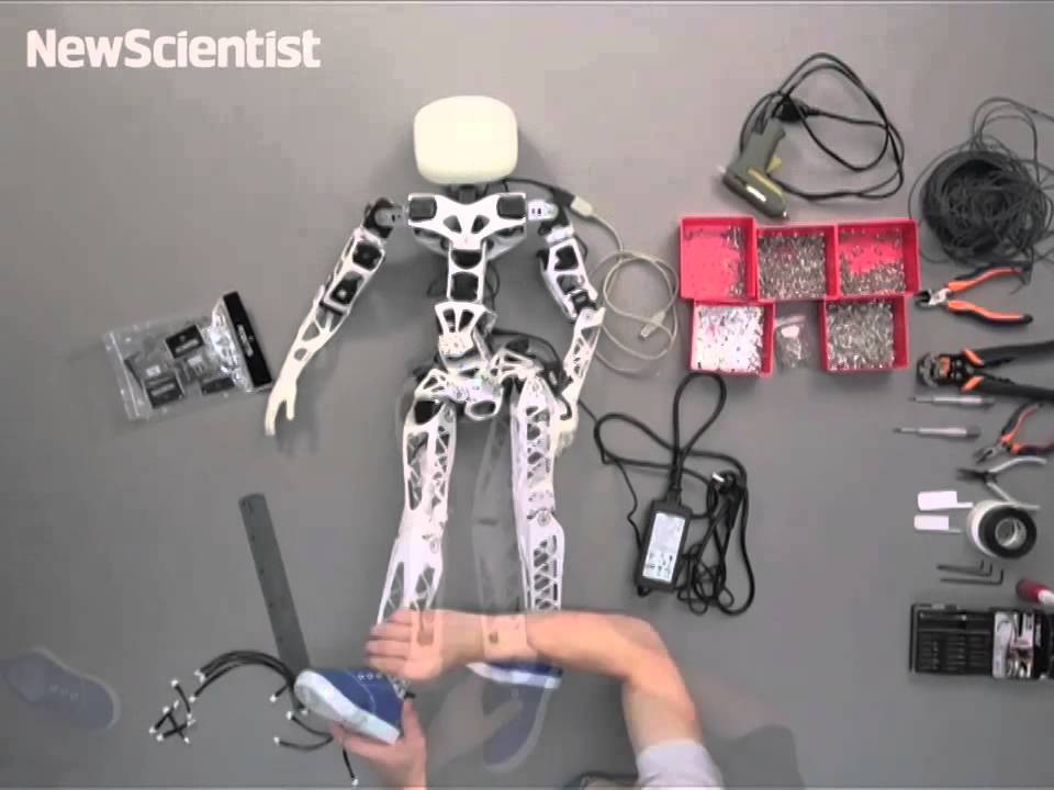 The creation of the digital model was carried out in parallel in two popular 3D design programs - ZBrush and Maya. More specifically, the artist designed the rough workpiece in ZBrush, completed it in Maya, and returned to ZBrush again for final detailing and preparation for 3D printing.
Creation of a 3D printed robot
Next, the 3D printed robot was 3D printed using SLA printing technology, which explains the high quality and good detail of the figurine. True, there were some troubles during printing, in connection with which the artist had to completely redo one fragment of the robot. The next step was final processing and painting. Since SLA samples require little to no cleaning, the first step didn't take long. The main difficulties were in painting the product using the airbrush method. Achieving the effect of worn and aged is not easy, and Paul spent a lot of effort and energy to achieve the optimal result.
And he speaks for himself. Although the 3D printed steampunk robot was meant to be an exclusive project, its implementation is so impressive that there will certainly be many who want to buy a copy of the amazing product.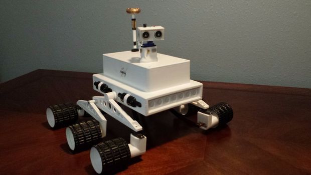 3D Printer Want another one?!
Why is this needed?
Well, let's say you have your own large printer and you can print fairly large objects. Do you believe in the idea of movement reprap , the printer must be able to reproduce itself!
Or you want to challenge yourself and finally understand how the 3D printer works.
Or your current 3D printer is just sitting in the corner of the room gathering dust because you have already printed everything that came to mind, and the most difficult task that worries all 3d printing professionals is how to clone existing equipment on it.
Step 1: Preface
Let's be honest... the is not the ultra cheap printer. This is not Chery 3D printer for $60. This not is a way to save money or time.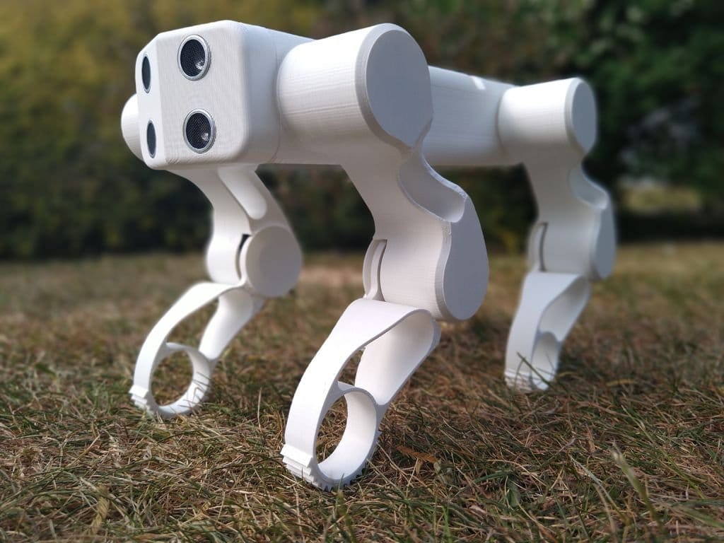 This is not first printer.
Now let's talk about what is .
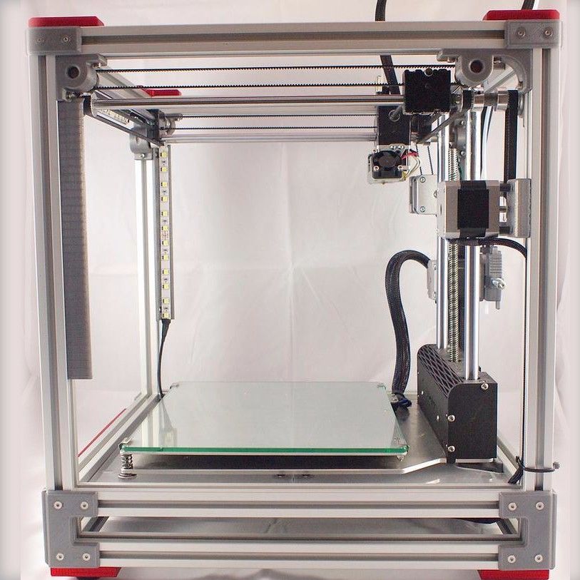
B 3Dtje mini 3D printer is:
- Damn easy to print
- Printed parts from PLA
- Everything fits within 200x200 print volume
- Most parts can be printed in 100x100 print volume
- Most parts are printed without supports , only in some cases they may be needed to improve the quality of
- Very few few needed tools
- Unlike most crafts that require a laser cutter, the CNC
- You can probably get away with a drill and a hacksaw to prepare 2 rods of the required size
- No source of MDF, or wood, or acrylic sheets or aluminum profiles, which can be expensive
- A Prusa i3 Clone
- This design is not new, nothing revolutionary, but it is reliable, prints well and works with any slicer
- Open source
- All model files can be downloaded free of charge
- You can download them and modify them as you like
- You can even sell them if you need to!
- Simple and interesting printing
- 19 models
- All parts are different and look very interesting together
- Easy to assemble
- All parts are connected with M3 screws and nuts.

- Cutting 2 to 4 metal rails
- Some 3d printed parts are assembled intuitively , you can even ignore the photo
- All parts are connected with M3 screws and nuts.
- Really fucking cool!
- Small, portable, low moving parts! This printer can print fast! (when properly configured)
- This 3D printer you will DIY , completely!!
Let's get started!
Step 2: Prerequisites
You will need the 3D Printer, or find someone with one.
- Printable area must be at least 200x200mm XY and maybe 200mm Z if you want to print with refills
- PLA 1 kg, can be different, but this is the most convenient option
- I honestly don't know how much it will take. Likely 500g or so
- Tools
- Screwdrivers for screws
- Pliers, cleaning tools for printed objects (a clerical knife is enough)
- Metric drills for opening / cleaning the printed hole (you can also use a screwdriver)
- Knowledge on how to build a 3D printer from scratch
- These are not hard requirements, but knowing how to deal with common printer problems will reduce the amount of swearing when things aren't perfect the first time.
- If you understand firmware Marlin it would be very cool to talk about this, as there is a desire to improve some things.
- These are not hard requirements, but knowing how to deal with common printer problems will reduce the amount of swearing when things aren't perfect the first time.
Step 3: Parts
Just to be clear, I've made a list of exactly what you need and what you can buy to make the best possible quality. But it will be more expensive. Therefore, you choose which set to buy - in principle, they will not differ. In addition, you can order all this from China, it will be cheaper, but the wait will be longer. In any case, you need to look for all the components in English, so we take them from the table and, for example, insert in alliexexspress search .
The table is located at this link.
Step 4: Printing Parts of
Now let's move on to the most interesting part, in my opinion - prototyping models of . To be honest, I really like to print different things, you feel that you can handle any task when you have a 3d printer at hand.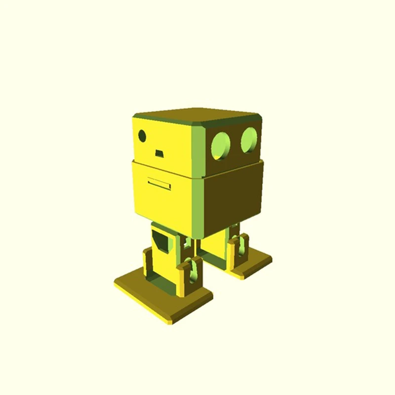 Okay, it's all lyrics.
Here is the project itself, where you can download 3d models for printer for free . Download and start preparing for printing.
The most important thing is to arrange the parts correctly on the table . The idea is to make the models have as few parts hanging in the air as possible. This will allow to drop support for . After all, they spoil the quality very much if you do slicing through Repetier Host with their auto-generation, and not draw them yourself.
You can watch a video showing the optimal arrangement of parts. Print settings I think you know how to do it, if not - there are articles about it with configuration files.
Step 5: Mounting
Assume we have printed everything. Someone may have decided to use metal guides, buying them, for example, from IKEA, and cutting them into sections of the desired length.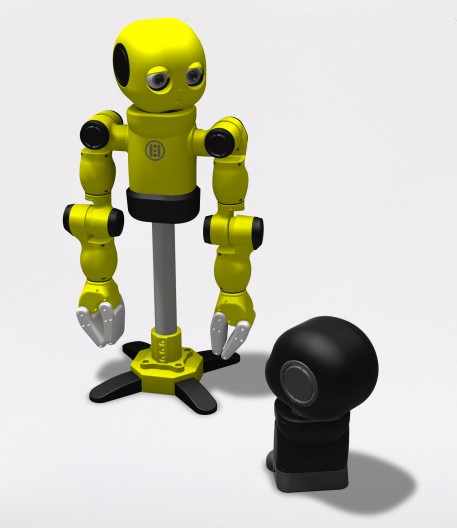 In any case, writing how to assemble this 3d printer does not make much sense, and it's too lazy, to be honest. In my opinion, there is nothing better than pictures!
Frame Assembly
First, I'll lay out how our miracle should look at the moment of medium readiness. Then we will see how the modules were assembled.
Association of the Y
Axis. This Axis drives The so -called bed . First we need to install the motor, put on the pulley on it. Then we install a freely rotating pulley on the other side and measure 9 for them0043 belt .
And now we will install the bed itself, which will fasten the two ends of the belt to us. Just don't forget to tighten the pulleys and anything that isn't tight yet. The substrate will be massive and it will be inconvenient to crawl there already.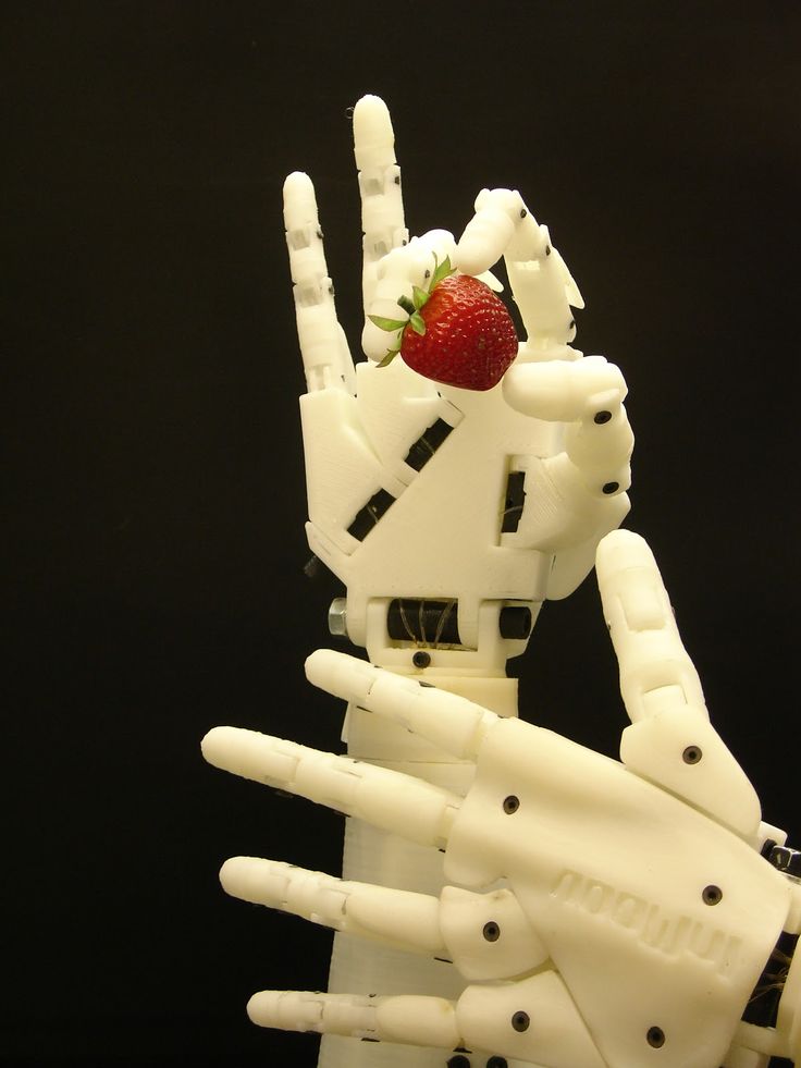 The connection will require 200mm x 6mm bolts, so have them ready right away.
It should be noted that the belt must be very tight . This will greatly affect print quality . If you cannot do this at the time of assembly, you can use special tensioner . It's basically a simple spring. As for the axes, in this case they are printed, although this is far from mandatory, just the name of the project obliges))
X-axis assembly
Depending on your printer, you may need to make a hole with a 3mm drill in the belt tensioner. This hole should be quite free.
- Attach the motor to the end of the x-axis with the connector down
- Attach 20T gear
- Insert 6mm rods 6mm x 180mm into the holes on the motor side. You need to cut these rods if you bought 200mm.
- Assemble the x-axis tensioner with either your own or printed tensioner bearing.
 Make sure the m3 nut is in the tensioner before proceeding.
 - Pass the belt from the left side (engine side), through the gearbox, through the idler bearing to the right side
- At this point, install belt tensioner to the right of the x-axis on the rods
- If you are happy with the length (make sure the x-axis of the tensioner is recessed quite a bit) you can cut the belt. Don't forget to leave extra strap length
- Attach LM6UU bearings in bottom bracket x
- All assembled, attach the straps to the carriage x
- Then it remains to adjust everything a little to make sure that nothing touches each other
Assembling the Z axis
Now we assemble the Z axis. If you have not installed the engines in the course of past work, it's time to do it. As you understand, they should stand on the left and on the right. We will install adapters for screw rods on them, where we will put them, holding them with a hexagon.
We stick the guides (parallel to the screw rods). We can say that we have finished assembling the case.
Step 6: Assembly of the electrical circuit.
How to lay the wiring is everyone's business. Here the options will be shown in the photo, but it's up to you to decide. The most important thing is to connect everything correctly. I'll also lay out the scheme, but it's better to see how this is done in ordinary 3d printers. For example, in order not to go far, you can go over the following articles directly on this site:
-
Exploring the features of a 3D printer
-
3D printer setup and calibration
-
Ramps 1.4 connection in 3d printer
It is not necessary to read everything - you can see the key places from the pictures and delve into their study.
The picture below shows the green power terminal.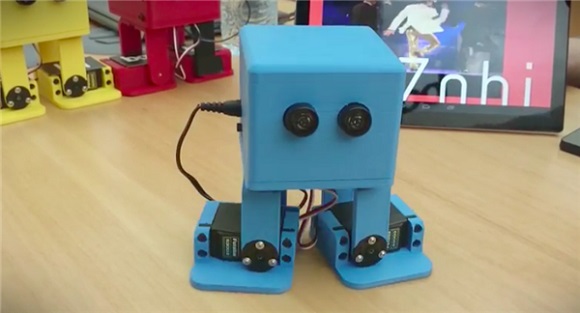 This is a very dangerous and unreliable thing that sometimes ignites - it is dangerous to leave a working 3d printer at home unattended. Therefore, in an article about Ramps, it is better to read how to be in this case.
Step 7: Firmware
Since you will (most likely) have an Arduino Mega as the brain of a 3d printer, uploading firmware to it will be quite simple. All you need is the Arduino IDE. The most standard firmware from Marlin. The main thing is to choose the correct configs for the board. I have not seen an article about the firmware on this resource, but it can be easily found on the Internet. Here are useful links:
- Firmware Marlin manual
- May be useful to someone info about electronics reprap , how is it functioning
Step 8: Testing
Finally time to print something! We note right away that the table must be covered with molar tape or Kapton, since we have it without heating.