3D printer bed leveling tool
3D Printer Leveling Tools | Everything You Need to Know
- Author
- Recent Posts
Martin
Besides many test devices, Martin now has his fourth own 3D printer running and prints as a hobby for friends, family and himself. He is happy to share his experience with each new article.
Latest posts by Martin (see all)
Disclosure: Links marked with * are Affiliate Links. I earn from qualifying purchases if you decide to make a purchase through these links – at no additional cost for you!
Leveling the print bed of a 3D printer is a big challenge in the beginning and requires some practice. With time, however, it becomes easier and easier and there are also a few tools with which this process can be made faster and easier.
There are printable print bed leveling tools that either directly measure the distance between the print bed and the nozzle, or are printed on the print bed. A print bed can also be leveled with paper, feeler gauges, calipers and dial gauges.
Find out how each of these tools work and where you can download or buy them in this article.
There are also sensors that can automatically level your print bed. In this article I compare two of the most popular of these sensors: BL-Touch vs. CR-Touch | Complete Comparison & Accuracy Test
Table of Contents:
- 1 Print Bed Leveling Tool from Ukansan > 3D Printer Leveling Tools
- 2 Ender 3 Leveling Test by Elmerohueso > 3D Printer Leveling Tools
- 3 Calibration Shapes Cura Plugin > 3D Printer Leveling Tools
- 4 Paper Method > 3D Printer Leveling Tools
- 5 Feeler Gauge > 3D Printer Leveling Tools
- 5.1 Feeler Gauge + LED
- 6 Caliper > 3D Printer Leveling Tools
- 7 Dial Gauge > 3D Printer Leveling Tools
Print Bed Leveling Tool from Ukansan
> 3D Printer Leveling ToolsBed Leveling Tool from ukansan made by Takshaka via Thingiverse
This print bed leveling tool from ukansan on Thingiverse (link to object) gives you visual feedback on how much the print bed is tilted.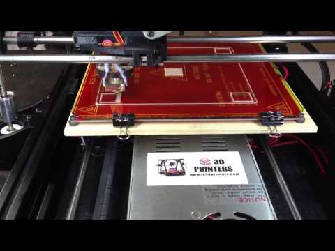
At the lower end of the tool there is a feeler stretched by rubber bands which, with a clever construction, transfers its height to two pointers by lever action. This transfers its movement in the Z-direction to an angular movement that is easier to read.
You can mount the tool on the X-axis of your 3D printer. When you move it over the print bed, the pointers will move depending on the inclination of the print bed. So you can quickly level your print bed or check if it still is.
Printing the tool is very easy, but it needs support structures that you have to remove after printing. Besides the self printed parts you need a M3 screw, a M3 washer, a M3 nut, some 1.75 mm filament and a rubber band.
Here is a video demonstrating the function and accuracy:
Ender 3 Leveling Test by Elmerohueso
> 3D Printer Leveling ToolsEnder 3 Level Test from Elmerohueso made by kmwilson343 via Thingiverse
This print bed leveling tool comes with its own G-code. Elmerohueso on Thingiverse designed this tool (link to object) specifically for the Ender 3, but it will work on any 3D printer with a 220 x 220 mm print bed.
Due to the inserted G-code the print head stops twice at all four corners so that you can set the distance between print bed and nozzle correctly there with the paper method (more on this below). After that, a skirt and a total of five discs are printed (4 at each corner and one in the middle).
Through the skirt and the five discs, you can usually visually see directly whether the print bed leveling is good or bad. You can get the exact result by removing the discs from the print bed after printing and measuring their thickness.
This tool is a nice extension of the paper method and allows you to get an accurate leveling assessment with little filament.
Calibration Shapes Cura Plugin
> 3D Printer Leveling Tools
In the very popular slicer Cura from Ultimaker you can create a very similar leveling tool like the one from Elmerohueso via a plugin in the marketplace. The plugin is called “Calibration Shapes” and is from 5axes. In this plugin are many calibration objects like temperature towers, retraction tests and much more.
You can find the Marketplace in Cura at the top right corner of the user interface. There you search for the plugin and install it. After that, you have to restart Cura once to be able to use the plugin.
The print bed leveling tool in this plugin consists of 9 rectangles evenly distributed over the print area and connected with straight lines. The complete construction consists of only one layer, which means that the print takes only about 10 to 15 minutes and consumes little material.
You should have already roughly adjusted the print bed via the paper method before you print this object. Most of the time you can already see visually where your print bed is too high or too low. If you use a somewhat transparent filament, it will be more translucent where the print bed is too high than where it is too low.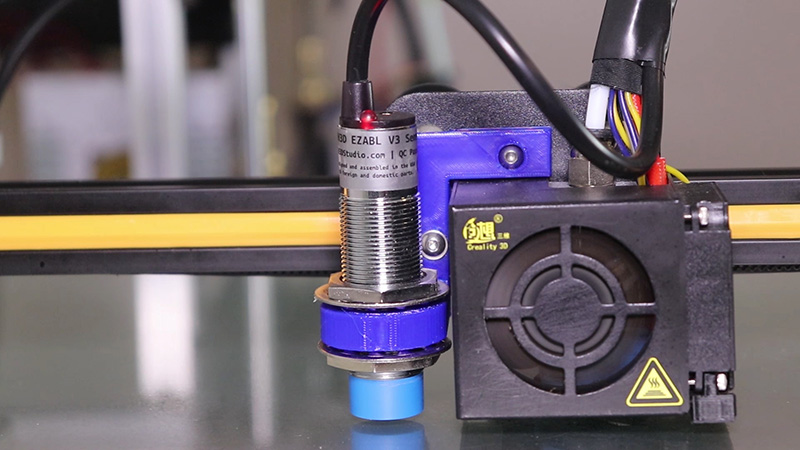 If you want to know exactly, you can measure the slices at the end with a caliper.
Paper Method
> 3D Printer Leveling Tools
With the paper method, the paper is the leveling tool. A normal piece of paper with a thickness of 0.1 mm is best suited. Since the paper method is so fast, easy and cheap, it should definitely belong to your standard skills.
The paper method requires some practice, as you need to get a feel for how much friction there is between the print bed, nozzle and paper when you move the paper back and forth between these two parts of your 3D printer.
The friction should not be too strong, but the paper should not be able to move without resistance either. If the friction is the same at all four corners, the print bed is well leveled.
Meanwhile, many 3D printing manufacturers deliver a small flexible plastic card with a thickness of 0.1 mm with their 3D printers. It is essentially a substitute for the paper and lasts much longer.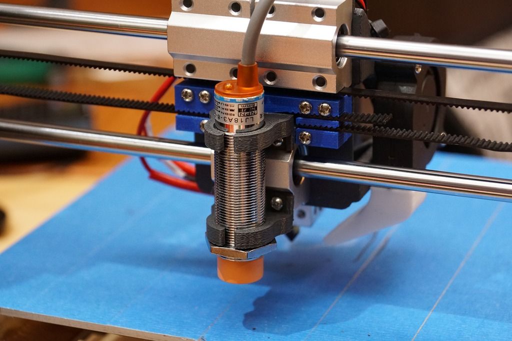
Feeler Gauge
> 3D Printer Leveling ToolsFeeler Gauge*
If you want to level your print bed a little more professionally than with a piece of paper, you can also get a feeler gauge*. A feeler gauge is a thin piece of metal that has been calibrated to a certain thickness. You can use it to very accurately set the distance between the nozzle and the print bed.
A feeler gauge is made of metal and is therefore not as elastic as paper. When the nozzle hits the metal, the metal will not yield. Depending on how the print bed is mounted, the friction between the nozzle, print bed and feeler gauge will be greater or less. With a feeler gauge, you should adjust the distance so that the nozzle just touches the feeler gauge.
And estimating when the feeler gauge just touches the nozzle takes a lot of practice. But the practice pays off because leveling with a feeler gauge can be much more accurate than with paper.
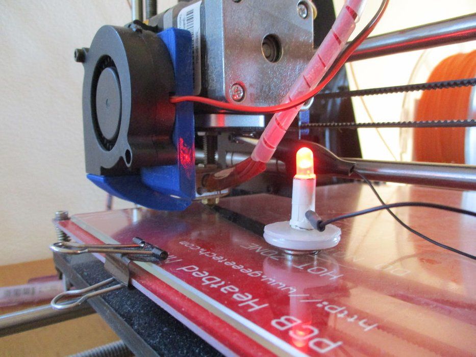
Feeler Gauge + LED
Feeler Gauge + LED Tool via instructablesTo solve the problem of poor testability of how much the nozzle touches the feeler gauge, someone has come up with an ingenious design. The result is a print bed leveling tool that shows you via an LED optically as soon as the nozzle touches the feeler gauge (link to the tool).
Since the nozzle, the print head and the feeler gauge are made of metal, they are also electrically conductive. As soon as they touch each other, an electrical circuit can be closed. This is exactly what happens with this tool.
As soon as the nozzle touches the feeler gauge, an electrical circuit closes and the LED lights up. This means you no longer need to estimate the friction and see immediately as soon as the feeler gauge touches the nozzle.
Caliper
> 3D Printer Leveling Tools Standard Caliper*
A caliper gauge* can also be used to level the printing plate of a 3D printer. Every caliper can measure heights. The difficulty here is to keep the caliper perfectly vertical to achieve an accurate result. You can either use the distance between the print head and the print bed or the X-axis to the print bed.
You should measure the distance at least at the four corners of the print bed to be able to estimate the inclination. However, before using the caliper gauge, you should have roughly leveled the print bed with the paper method. With the caliper, you then only check the position of the print bed to be sure.
Dial Gauge
> 3D Printer Leveling ToolsDial Gauge*
Print bed leveling with a dial gauge* is one of the most accurate methods available. With a dial gauge, you can measure the inclination of the print bed as it is done on large CNC machines in the industry.
You have to mount the dial gauge on your 3D printer so that the measured values are reproducible. For this, you can print yourself a mount or fix the dial gauge with screws or cable ties on the print head.
The dial gauge shows very precisely how much it gets compressed in the Z-direction. This allows you to measure the height or distance from the print bed to the dial gauge at several corners on the print bed.
Disclosure: This website is the property of Martin Lütkemeyer and is operated by Martin Lütkemeyer. Martin Lütkemeyer is a member of the Amazon Services LLC and other Affiliate Programs. These are affiliate advertising programs designed to enable websites to earn advertising revenue through advertising and linking to Amazon.com and others. Links marked with * are affiliate links.
Electronic Bed Level Tool - CHEPclub
Filament Friday
E-Leveler
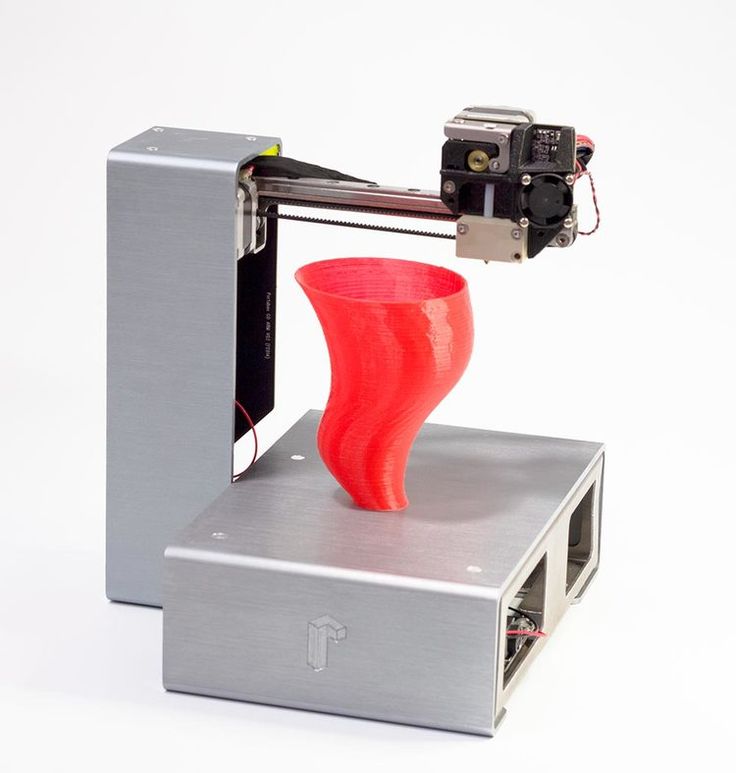
The Electronic Bed Leveling Tool
You can buy it Assembled or as a Kit on Amazon.
How the E-Leveler Works
You run the Filament Friday E-Leveler GCode files just like any 3D Print.
The GCode file will position the nozzle over each adjuster with the perfect 5.8 mm Z-offset for the E-Leveler.
It will automatically move to the corner (left front first) so you can level that corner with the E-Leveler so the LED just turns on. The GCode will automatically move to the next position after 20 seconds so you can level the next corner.
It continues until all corners are leveled.
(Full Instructions are under the Download File Grey Block below).
G-Code Files To Use Your E-Leveler
Right Click on "Download File" below and Select "Save Link As" to save to your computer.
Unzip the file and you will find a Folder with three separate sub-folders:
Ender 2 size (180x180 bed), Ender 3 Size (220x220 bed) and Ender 3 Max Size (300x300 Bed).
Choose the folder that matches closest to your printer's size (it doesn't have to be an Ender just similar in size) and copy the two GCode files, within the folder for your size printer, to your SD card. Insert the SD card into your printer and follow the instructions below.
To Download: |
Ender 2 Pro Ender 3 V2 and Ender 3 Ender 3 Max | ||
Instructions
| Video of E-Leveler Used on a Neptune 2 (Ender 3 Clone) Squares Test Print on Ender 3 Pro |
 gcode file just like any 3D print and it will position to the front left corner.
Assembly Instructions for kit version:
bed_level_tool_assembly_and_instructions. pdf pdf |
Optional Accessories you can 3D Print
| 3D Print the red End Cap shown in the picture and make the Electronic Bed Level more stable and keep the battery holder off the bed. It inserts on to the LED side of the board. | Switch alignment tool. Download and 3D print it to help you center the switch when you solder it or resolder it. |
Original Video Introducing the Tool and Accuracy Test Video
3D Printer Platen Leveling Method?
There are several ways.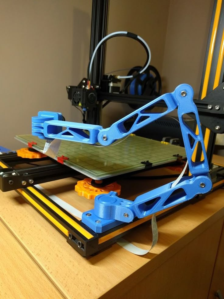
1) The simplest method is the business card/paper method.
This video shows how easy it is: Leveling the platform
You should feel equal resistance between the hotplate and the table from all sides. Some 3D printers have 3 screws holding the table (ex. Solidoodle), while others have 4 screws on each edge (ex. Prusa i3). On some 3D printers you have to turn the screw with a screwdriver to adjust it (like Solidoodle 3) and on some you have a nut (mostly a vane nut) (like Solidoodle 4).
I find that most people move the extruder when adjusting the table by driving the motors. I think a faster way is to stop the engines (in the Repetier host it's the "Stop engine" button) and move the portal manually.
Tutorial: 3D Printing Guides - Table Leveling
2) The second one is just a more advanced version of the above. You use a dial indicator/micrometer attached to the extruder and make sure the number on the dial is as close as possible on all edges.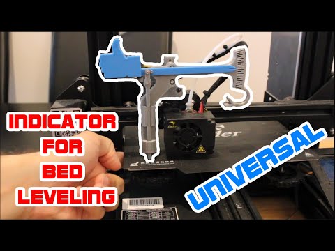
Align the build plate on the RepRap / RepStrap 3D printer using the Mitutoyo kit test indicator
Micrometer op 3D printer
There are also digital versions of this tool.
You may need to print or make some other way to be able to attach the micrometer to the extruder (you may already have one for your 3D printer on Thingiverse).
Now, remember I mentioned that you adjust the height of the edges of the platen with a screw/nut? Well, since there is a lot of vibration during printing, they tend to fail, and that may explain why you end up correcting it over and over again. What I have found to solve this problem is to use one drop of loctite (cyanoacrylate glue) in the middle of the nut/screw. One drop will secure it in place, but also won't make it impossible to unscrew it in the future.
3) Setting the automatic table alignment on the 3D printer, if it can be changed enough: 3D Printing Tutorials: Set up automatic tilt compensation when leveling the table!.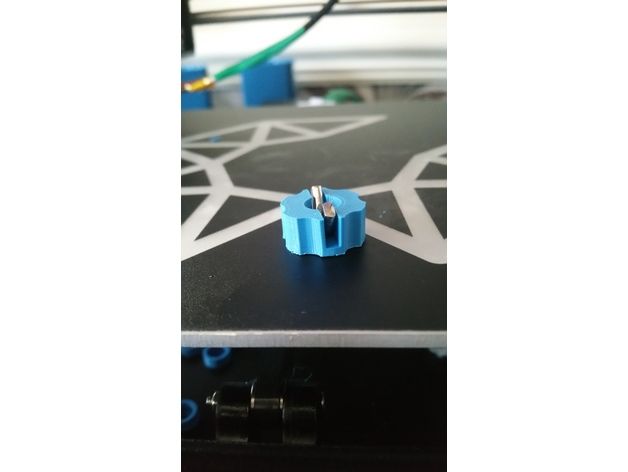
Finally, if you cannot level the table no matter what, it may not be level. This is usually caused by deformation. Both printed circuit boards and aluminum tables can warp. With the first, just put a glass table on it and you should be fine. Deformed aluminum is quite difficult to flatten. In this extreme situation, you may need to cut and drill a new aluminum sheet, preferably a mm thicker, which is less likely to warp under the same conditions. I think this happens when you either set the table temperature too high and/or the aluminum table thickness is too thin (bad or cheap 3d printer design).
3D printing for dummies or "what is a 3D printer?"
- 1 3D printing term
- 2 3D printing methods
- 2.1 Extrusion printing
- 2.2 Melting, sintering or gluing
- 2.3 Stereolithography
- 2.4 Lamination
- 3 Fused Deposition Printing (FDM)
- 3.
 1 Consumables
 - 3.2 Extruder
- 3.3 Working platform
- 3.4 Positioners
- 3.5 Control
- 3.6 Varieties of FDM printers
- 4 Laser Stereolithography (SLA)
- 4.1 Lasers and projectors
- 4.2 Cuvette and resin
- 4.3 Varieties of Stereolithography Printers
3D printing term
The term 3D printing has several synonyms, one of which quite briefly and accurately characterizes the essence of the process - "additive manufacturing", that is, production by adding material. The term was not coined by chance, because this is the main difference between multiple 3D printing technologies and the usual methods of industrial production, which in turn received the name "subtractive technologies", that is, "subtractive". If during milling, grinding, cutting and other similar procedures, excess material is removed from the workpiece, then in the case of additive manufacturing, material is gradually added until a solid model is obtained.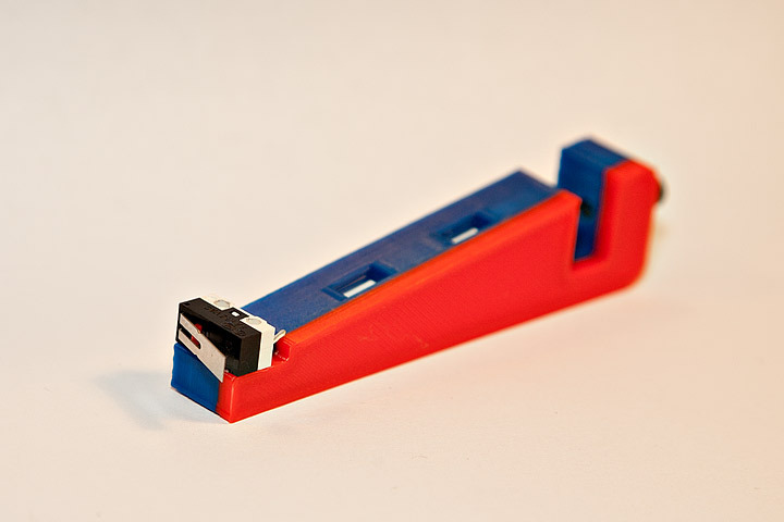
Soon 3D printing will even be tested on the International Space Station
Strictly speaking, many traditional methods could be classified as "additive" in the broad sense of the word - for example, casting or riveting. However, it should be borne in mind that in these cases, either the consumption of materials is required for the manufacture of specific tools used in the production of specific parts (as in the case of casting), or the whole process is reduced to joining ready-made parts (welding, riveting, etc.). In order for the technology to be classified as “3D printing”, it is necessary to build the final product from raw materials, not blanks, and the formation of objects must be arbitrary - that is, without the use of forms. The latter means that additive manufacturing requires a software component. Roughly speaking, additive manufacturing requires computer control so that the shape of final products can be determined by building digital models. It was this factor that delayed the widespread adoption of 3D printing until the moment when numerical control and 3D design became widely available and highly productive.
3D printing methods
3D printing technologies are numerous, and there are even more names for them due to patent restrictions. However, you can try to divide technologies into main areas:
Extrusion printing
This includes methods such as deposition fusion (FDM) and multi-jet printing (MJM). This method is based on the extrusion (extrusion) of consumables with the sequential formation of the finished product. As a rule, consumables consist of thermoplastics or composite materials based on them.
Melting, sintering or bonding
This approach is based on bonding powdered material together. Formation is done in different ways. The simplest is gluing, as is the case with 3D inkjet printing (3DP). Such printers deposit thin layers of powder onto the build platform, which are then selectively bonded with a binder. Powders can be made up of virtually any material that can be ground to a powder—plastic, wood, metal.
This model of James Bond's Aston Martin was successfully printed on a Voxeljet SLS printer and blown up just as successfully during the filming of Skyfall instead of the expensive original
sintering (SLS and DMLS) and smelting (SLM), which allow you to create all-metal parts. As with 3D inkjet printing, these devices apply thin layers of powder, but the material is not glued together, but sintered or melted using a laser. Laser sintering (SLS) is used to work with both plastic and metal powders, although metal pellets usually have a more fusible shell, and after printing they are additionally sintered in special ovens. DMLS is a variant of SLS installations with more powerful lasers that allow sintering metal powders directly without additives. SLM printers provide not just sintering of particles, but their complete melting, which allows you to create monolithic models that do not suffer from the relative fragility caused by the porosity of the structure. As a rule, printers for working with metal powders are equipped with vacuum working chambers, or they replace air with inert gases. Such a complication of the design is caused by the need to work with metals and alloys subject to oxidation - for example, with titanium.
Stereolithography
How an SLA printer works
Stereolithography printers use special liquid materials called "photopolymer resins". The term "photopolymerization" refers to the ability of a material to harden when exposed to light. As a rule, such materials react to ultraviolet irradiation.
Resin is poured into a special container with a movable platform, which is installed in a position near the surface of the liquid. The layer of resin covering the platform corresponds to one layer of the digital model. Then a thin layer of resin is processed by a laser beam, hardening at the points of contact. At the end of illumination, the platform together with the finished layer is immersed to the thickness of the next layer, and illumination is performed again.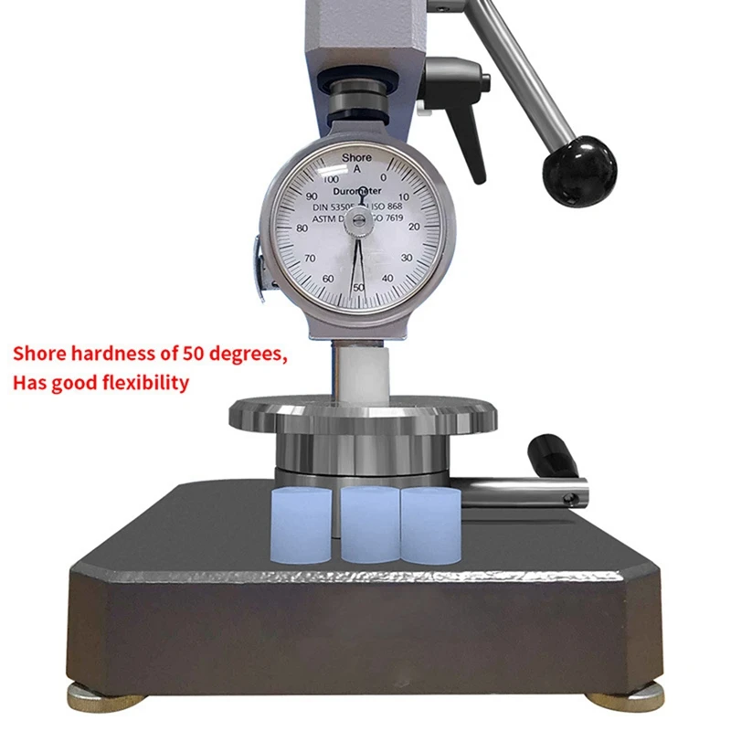
Lamination
Laminating (LOM) 3D printers workflow
Some 3D printers build models using sheet materials - paper, foil, plastic film.
Layers of material are glued on top of each other and cut along the contours of the digital model using a laser or a blade.
These machines are well suited for prototyping and can use very cheap consumables, including regular office paper. However, the complexity and noise of these printers, coupled with the limitations of the models they produce, limit their popularity.
Fused deposition modeling (FDM) and laser stereolithography (SLA) have become the most popular 3D printing methods used in the home and office.
Let's take a closer look at these technologies.
Fused Deposition Printing (FDM)
FDM is perhaps the simplest and most affordable 3D construction method, which makes it very popular.
High demand for FDM printers is driving device and consumable prices down rapidly, along with technology advances towards ease of use and improved reliability.
Consumables
ABS filament spool and finished model
FDM printers are designed to print with thermoplastics, which are usually supplied as thin filaments wound on spools. The range of "clean" plastics is very wide. One of the most popular materials is polylactide or "PLA plastic". This material is made from corn or sugar cane, which makes it non-toxic and environmentally friendly, but makes it relatively short-lived. ABS plastic, on the other hand, is very durable and wear-resistant, although it is susceptible to direct sunlight and can release small amounts of harmful fumes when heated. Many plastic items that we use on a daily basis are made from this material: housings for household appliances, plumbing fixtures, plastic cards, toys, etc.
In addition to PLA and ABS, printing is possible with nylon, polycarbonate, polyethylene and many other thermoplastics that are widely used in modern industry.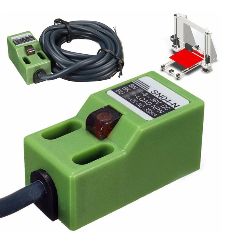 More exotic materials are also possible, such as polyvinyl alcohol, known as "PVA plastic". This material dissolves in water, which makes it very useful for printing complex geometric patterns. But more on that below.
Model made from Laywoo-D3. Changing the extrusion temperature allows you to achieve different shades and simulate annual rings
It is not necessary to print with homogeneous plastics. It is also possible to use composite materials imitating wood, metals, stone. Such materials use all the same thermoplastics, but with impurities of non-plastic materials.
So, Laywoo-D3 consists partly of natural wood dust, which allows you to print "wooden" products, including furniture.
The material called BronzeFill is filled with real bronze, and models made from it can be ground and polished, achieving a high similarity to products made from pure bronze.
One has only to remember that thermoplastics serve as a binding element in composite materials - they determine the thresholds of strength, thermal stability and other physical and chemical properties of finished models.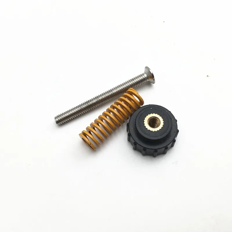
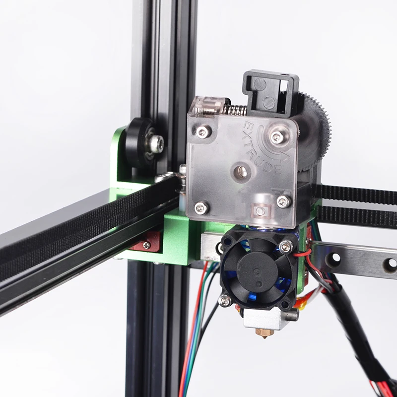
Extruder
Extruder - FDM print head. Strictly speaking, this is not entirely true, because the head consists of several parts, of which only the feed mechanism is directly "extruder". However, by tradition, the term "extruder" is commonly used as a synonym for the entire print assembly.
FDM extruder general design
The extruder is designed for melting and applying thermoplastic thread. The first component is the thread feed mechanism, which consists of rollers and gears driven by an electric motor. The mechanism feeds the thread into a special heated metal tube with a small diameter nozzle, called a "hot end" or simply a "nozzle". The same mechanism is used to remove the thread if a change of material is needed.
The hot end is used to heat and melt the thread fed by the puller. As a rule, nozzles are made from brass or aluminum, although more heat-resistant, but also more expensive materials can be used.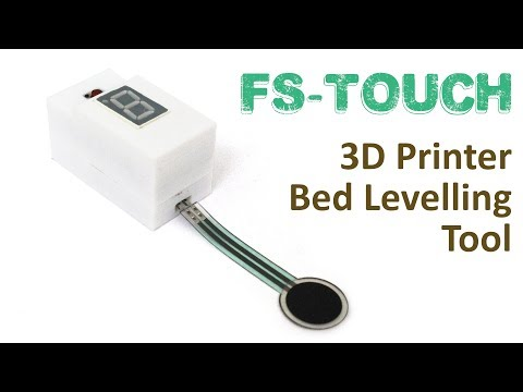 For printing with the most popular plastics, a brass nozzle is quite enough. The “nozzle” itself is attached to the end of the tube with a threaded connection and can be replaced with a new one in case of wear or if a change in diameter is necessary. The nozzle diameter determines the thickness of the molten filament and, as a result, affects the print resolution. The heating of the hot end is controlled by a thermistor. Temperature control is very important, because when the material is overheated, pyrolysis can occur, that is, the decomposition of plastic, which contributes both to the loss of the properties of the material itself and to clogging of the nozzle.
PrintBox3D One FDM Printer Extruder
To prevent the filament from melting too early, the top of the hot end is cooled by heatsinks and fans. This point is of great importance, since thermoplastics that pass the glass transition temperature significantly expand in volume and increase the friction of the material with the walls of the hot end. If the length of such a section is too long, the pulling mechanism may not have enough strength to push the thread.
The number of extruders may vary depending on the purpose of the 3D printer. The simplest options use a single printhead. The dual extruder greatly expands the capabilities of the device, allowing you to print one model in two different colors, as well as using different materials. The last point is important when building complex models with overhanging structural elements: FDM printers cannot print “over the air”, since the applied layers require support. In the case of hinged elements, temporary support structures have to be printed, which are removed after printing is completed. The removal process is fraught with damage to the model itself and requires accuracy. In addition, if the model has a complex structure with internal cavities that are difficult to access, building conventional supports may not be practical due to the difficulty in removing excess material.
Finished model with PVA supports (white) before and after washing
In such cases, the same water-soluble polyvinyl alcohol (PVA) comes in handy. Using a dual extruder, you can build a model from waterproof thermoplastic using PVA to create supports.
After printing, PVA can simply be dissolved in water and a complex product of perfect quality can be obtained.
Some FDM printers can use three or even four extruders.
Work platform
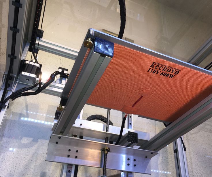
Heated platform covered with removable glass work table
Models are built on a special platform, often equipped with heating elements. Preheating is required for a wide range of plastics, including the popular ABS, which are subject to a high degree of shrinkage when cooled. The rapid loss of volume by cold coats compared to freshly applied material can lead to model distortion or delamination. The heating of the platform makes it possible to significantly equalize the temperature gradient between the upper and lower layers.
Heating is not recommended for some materials. A typical example is PLA plastic, which requires a fairly long time to harden. Heating PLA can lead to deformation of the lower layers under the weight of the upper ones. When working with PLA, measures are usually taken not to heat up, but to cool the model. Such printers have characteristic open cases and additional fans blowing fresh layers of the model.
Calibration screw for work platform covered with blue masking tape
The platform needs to be calibrated before printing to ensure that the nozzle does not hit the applied layers or move too far causing air-to-air printing resulting in plastic vermicelli. The calibration process can be either manual or automatic. In manual mode, calibration is performed by positioning the nozzle at different points on the platform and adjusting the platform inclination using the support screws to achieve the optimal distance between the surface and the nozzle.
As a rule, platforms are equipped with an additional element - a removable table. This design simplifies the cleaning of the working surface and facilitates the removal of the finished model. Stages are made from various materials, including aluminum, acrylic, glass, etc. The choice of material for the manufacture of the stage depends on the presence of heating and consumables for which the printer is optimized.
For a better adhesion of the first layer of the model to the surface of the table, additional tools are often used, including polyimide film, glue and even hairspray! But the most popular tool is inexpensive, but effective masking tape. Some manufacturers make perforated tables that hold the model well but are difficult to clean. In general, the expediency of applying additional funds to the table depends on the consumable material and the material of the table itself.
Positioning mechanisms
Scheme of operation of positioning mechanisms
Of course, the print head must move relative to the working platform, and unlike conventional office printers, positioning must be carried out not in two, but in three planes, including height adjustment.
Positioning pattern may vary. The simplest and most common option involves mounting the print head on perpendicular guides driven by stepper motors and providing positioning along the X and Y axes.
Vertical positioning is carried out by moving the working platform.
On the other hand, it is possible to move the extruder in one plane and the platforms in two.
SeemeCNC ORION Delta Printer
One option that is gaining popularity is the use of a delta coordinate system.
Such devices are called "delta robots" in the industry.
In delta printers, the print head is suspended on three manipulators, each of which moves along a vertical rail.
The synchronous symmetrical movement of the manipulators allows you to change the height of the extruder above the platform, and the asymmetric movement causes the head to move in the horizontal plane.
A variant of this system is the reverse delta design, where the extruder is fixed to the ceiling of the working chamber, and the platform moves on three support arms.
Delta printers have a cylindrical build area, and their design makes it easy to increase the height of the working area with minimal design changes by lengthening the rails.
In the end, everything depends on the decision of the designers, but the fundamental principle does not change.
Control
Typical Arduino-based controller with add-on modules
FDM printer operation, including nozzle and platform temperature, filament feed rate, and stepper motors for positioning the extruder, is controlled by fairly simple electronic controllers. Most controllers are based on the Arduino platform, which has an open architecture.
The programming language used by printers is called G-code (G-Code) and consists of a list of commands executed in turn by the 3D printer systems. G-code is compiled by programs called "slicers" - standard 3D printer software that combines some of the features of graphics editors with the ability to set print options through a graphical interface. The choice of slicer depends on the printer model. RepRap printers use open source slicers such as Skeinforge, Replicator G and Repetier-Host. Some companies make printers that require proprietary software.
Program code for printing is generated using slicers
As an example, we can mention Cube printers from 3D Systems. There are companies that offer proprietary software but allow third-party software, as is the case with the latest generation of MakerBot 3D printers.
Slicers are not designed for 3D design per se. This task is done with CAD editors and requires some 3D design skills. Although beginners should not despair: digital models of a wide variety of designs are offered on many sites, often even for free. Finally, some companies and individuals offer 3D design services for custom printing.
Finally, 3D printers can be used in conjunction with 3D scanners to automate the process of digitizing objects. Many of these devices are designed specifically to work with 3D printers.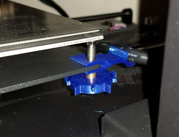 Notable examples include the 3D Systems Sense handheld scanner and the MakerBot Digitizer handheld desktop scanner.
MakerBot Replicator 5th Generation FDM Printer with built-in control module on the top of the frame
The user interface of a 3D printer can consist of a simple USB port for connecting to a personal computer. In such cases, the device is actually controlled by the slicer.
The disadvantage of this simplification is a rather high probability of printing failure when the computer freezes or slows down.
A more advanced option includes an internal memory or memory card interface to make the process standalone.
These models are equipped with control modules that allow you to adjust many print parameters (such as print speed or extrusion temperature). The module may include a small LCD display or even a mini-tablet.
Varieties of FDM printers
Professional Stratasys Fortus 360mc FDM printer that allows printing with nylon
FDM printers are very, very diverse, ranging from the simplest homemade RepRap printers to industrial installations capable of printing large-sized objects.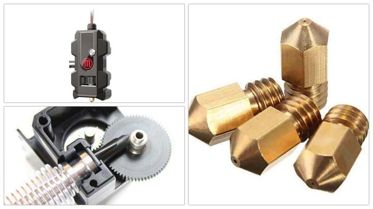
Stratasys, founded by FDM inventor Scott Crump, is a leader in industrial plant manufacturing.
You can build the simplest FDM printers yourself. Such devices are called RepRap, where "Rep" indicates the possibility of "replication", that is, self-reproduction.
RepRap printers can be used to print custom built plastic parts.
Controller, rails, belts, motors and other components can be easily purchased separately.
Of course, assembling such a device on your own requires serious technical and even engineering skills.
Some manufacturers make it easy by selling DIY kits, but these kits still require a good understanding of the technology. RepRap Printers
And, despite their "homemade nature", RepRap printers are quite capable of producing models with quality at the level of expensive branded counterparts.
Ordinary users who do not want to delve into the intricacies of the process, but require only a convenient device for household use, can purchase a ready-made FDM printer.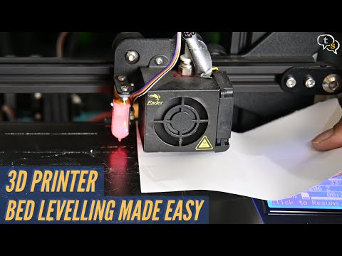
Many companies are focusing on the development of the consumer market segment, offering 3D printers for sale that are ready to print “straight out of the box” and do not require serious computer skills.
3D Systems Cube consumer 3D printer
The most famous example of a consumer 3D printer is the 3D Systems Cube.
While it doesn't boast a huge build area, ultra-fast print speed, or superb model build quality, it's easy to use, affordable, and safe: This printer has received the necessary certification to be used even by children.
Mankati FDM printer demonstration: http://youtu.be/51rypJIK4y0
Laser Stereolithography (SLA)
Stereolithographic 3D printers are widely used in dental prosthetics
Stereolithographic printers are the second most popular and widespread after FDM printers.
These units deliver exceptional print quality.
The resolution of some SLA printers is measured in a matter of microns - it is not surprising that these devices quickly won the love of jewelers and dentists.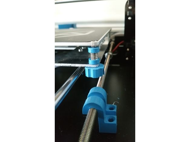
The software side of laser stereolithography is almost identical to FDM printing, so we will not repeat ourselves and will only touch on the distinctive features of the technology.
Lasers and projectors
Projector illumination of a photopolymer model using the Kudo3D Titan DLP printer as an example
The cost of stereolithographic printers is rapidly declining, due to growing competition due to high demand and the use of new technologies that reduce the cost of construction.
Although the technology is collectively referred to as "laser" stereolithography, most recent developments use UV LED projectors for the most part.
Projectors are cheaper and more reliable than lasers, do not require the use of delicate mirrors to deflect the laser beam, and have higher performance. The latter is explained by the fact that the contour of the whole layer is illuminated as a whole, and not sequentially, point by point, as is the case with laser options. This variant of the technology is called projection stereolithography, "DLP-SLA" or simply "DLP". However, both options are currently common - both laser and projector versions.
Cuvette and resin
Photopolymer resin is poured into the cuvette
A photopolymer resin that looks like epoxy is used as consumables for stereolithographic printers. Resins can have a variety of characteristics, but they all share one key feature for 3D printing applications: these materials harden when exposed to ultraviolet light. Hence, in fact, the name "photopolymer".
When polymerized, resins can have a wide variety of physical characteristics. Some resins are like rubber, others are hard plastics like ABS. You can choose from different colors and degrees of transparency. The main disadvantage of resins and SLA printing in general is the cost of consumables, which significantly exceeds the cost of thermoplastics.
On the other hand, stereolithographic printers are mainly used by jewelers and dentists who do not need to build large parts but appreciate the savings from fast and accurate prototyping.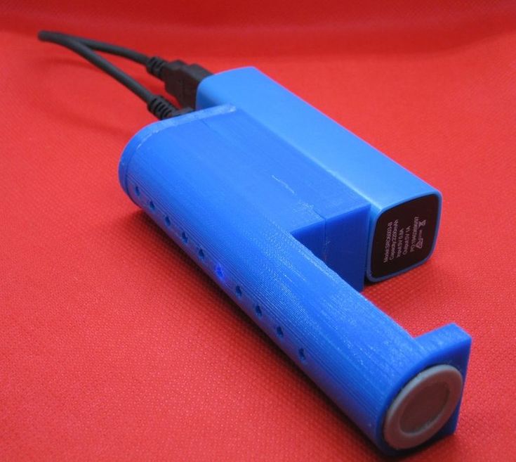 Thus, SLA printers and consumables pay for themselves very quickly.
An example of a model printed on a laser stereolithographic 3D printer
Resin is poured into a cuvette, which can be equipped with a lowering platform. In this case, the printer uses a leveling device to flatten the thin layer of resin covering the platform just prior to irradiation. As the model is being made, the platform, together with the finished layers, is “embedded” in the resin. Upon completion of printing, the model is removed from the cuvette, treated with a special solution to remove liquid resin residues and placed in an ultraviolet oven, where the final illumination of the model is performed.
Some SLA and DLP printers work in an "inverted" scheme: the model is not immersed in the consumable, but "pulled" out of it, while the laser or projector is placed under the cuvette, and not above it. This approach eliminates the need to level the surface after each exposure, but requires the use of a cuvette made of a material transparent to ultraviolet light, such as quartz glass.
The accuracy of stereolithographic printers is extremely high. For comparison, the standard for vertical resolution for FDM printers is considered to be 100 microns, and some variants of SLA printers allow you to apply layers as thin as 15 microns. But this is not the limit. The problem, rather, is not so much in the accuracy of lasers, but in the speed of the process: the higher the resolution, the lower the print speed. The use of digital projectors allows you to significantly speed up the process, because each layer is illuminated entirely. As a result, some DLP printer manufacturers claim to be able to print with a vertical resolution of one micron!
Video from CES 2013 showing Formlabs Form1 stereolithography 3D printer in action: http://youtu.be/IjaUasw64VE
Stereolithography Printer Options
Formlabs Form1 Desktop Stereolithography Printer
As with FDM printers, SLA printers come in a wide range in terms of size, features and cost.