Can you 3d print screws
3D Printing Threads and Adding Threaded Inserts to 3D Printed Parts (With Video)
There are many ways to attach screws to 3D printed parts, including inserts, tapping, and even 3D printed screw threads.
Screws are among the most popular fasteners in any material. Can you use off-the-shelf screws with your 3D printed parts? The answer is a clear yes, for both stereolithography (SLA) and selective laser sintering (SLS) parts.
In this article, we explore different methods of using metal screws with 3D printed parts, and provide some tips for incorporating screw threads directly into your 3D design.
Watch our application video about 3D printing threads and threaded inserts for 3D printed plastics.
Video Guide
Having trouble finding the best 3D printing technology for your needs? In this video guide, we compare FDM, SLA, and SLS technologies across popular buying considerations.
Watch the Videos
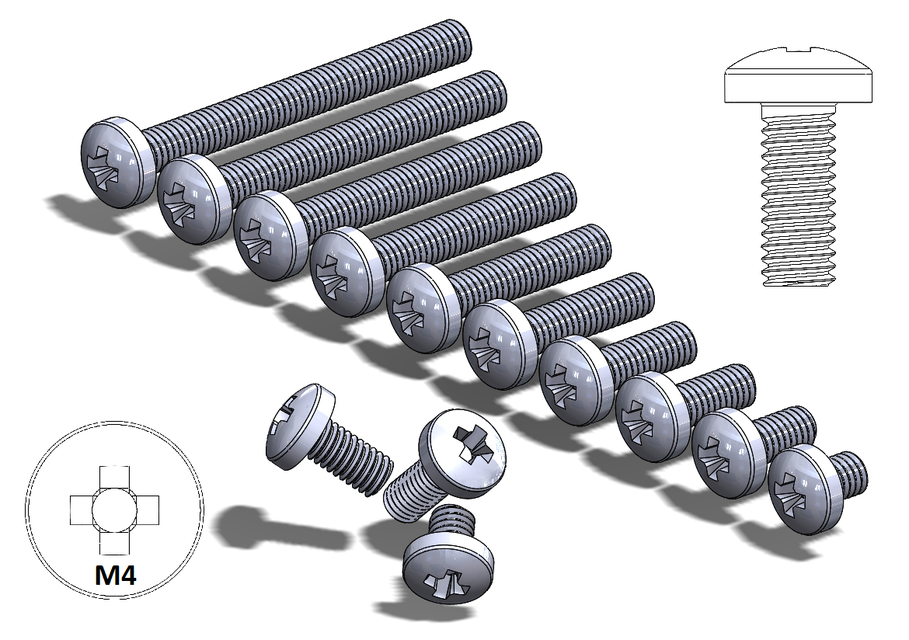
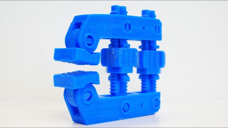
Let’s take a look at the various design options for 3D printed threads, which we’ve collected over the years within Formlabs and based on feedback from our customers. Our test part is designed to showcase all these methods at once:
We’ve grouped these options based on the type of fastening, with pros and cons of each option listed for different use cases.
Sample part
See and feel Formlabs quality firsthand. We’ll ship a free sample part printed on an SLA or SLS 3D printer to your office.
Request a Free Sample Part
In this section, we look at three ways to incorporate inserts and nuts into your completed 3D prints for strong, long-lasting fastening that stands up to multiple cycles of assembly and disassembly.
Pros
-
Very good hold into 3D printed parts
-
Metal threads are strong and wear-resistant
-
Installs with a simple press fit
Screw-to-expand inserts are cylindrical, with a slight taper and knurling on the exterior surfaces. During the design stage, incorporate a boss with a depth and diameter based on the insert’s specs into your part.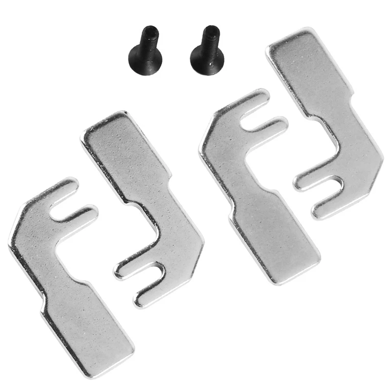 Print and post-process the part as normal, following the usual steps for SLA or SLS post-processing, taking care to make sure no extra material remains inside the cavity, and install the insert with a simple press fit. Adding a screw will press the knurled surface into the surrounding printed material, creating a strong friction fit.
Tip for using screw-to-expand inserts with 3D printed parts made with SLA 3D printing: Wash the part as normal, insert the screw-to-expand insert, install a screw, and post-cure the part with the screw in place. Saving this step for last reduces the chance that the insert will crack the surrounding material when expanded.
Heat-set threaded inserts are designed to be installed into thermoplastics using a soldering iron with an installation tip. They can also be used as glue-in inserts in thermoset materials, such as SLA parts.
To install in a thermoplastic part, like one printed with SLS Powders, follow the installation instructions for your particular hardware.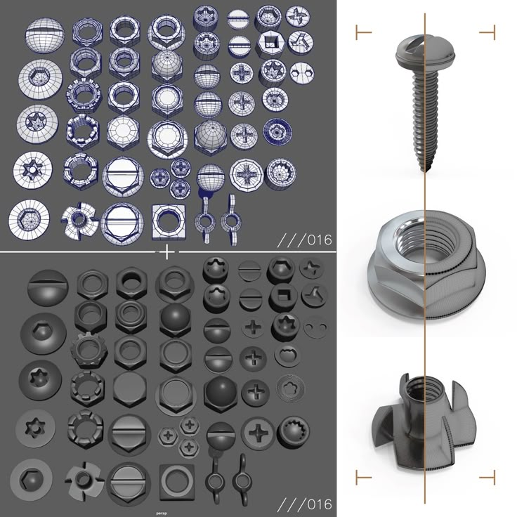 The typical process is to use a soldering iron, with or without a special attachment, to heat the insert, which conducts heat into the surrounding plastic. The surrounding material softens and, by pressing down with the soldering iron, you can gently press the insert into the printed part. Be sure to allow enough time for the material to cool down and regain strength before installing a screw.
To install in a thermoset part, like one printed with SLA Resins, glue can be used to hold a heat-set insert in place. Unlike with traditional installation, make sure to design your boss to match the widest diameter of the insert, and use a bead of cyanoacrylate (CA) glue or epoxy to hold it in place when installed. Be sure to allow enough time for your glue to fully cure before installing a screw.
Note: In the SLS 3D printed part photographed for this article, the boss is sized for a press-fit, as we recommend here for thermoset plastics. This also works, with a drop of glue or epoxy, for thermoplastic parts, but won’t have as strong a hold as a true heat-set installation.
Although an additional step of soldering or gluing is required, heat-set threaded inserts for both SLS and SLA parts offer improved security and strength compared to screw-to-expand inserts With either method, these are a great option to gain a little extra security and strength compared to screw-to-expand inserts, although the additional step and equipment may be inconvenient.
Cons
-
Pocket or boss needs to be designed into the part, and accessible after printing
-
Depending on geometry, may require glue and curing time
Designing a pocket or boss that securely holds a nut into the part itself is another method to get metal-on-metal contact. Hexagonal or square nuts can be used, and even locking nuts are possible to accommodate. There are many design variations for this method—just make sure your pocket or boss is easily accessible (i.e. not on an interior surface) so that the nut can be installed. For extra security, a drop of cyanoacrylate (CA) glue will hold the nut in place.
White Paper
Stereolithography (SLA) 3D printers such as the Formlabs Form 3+ have high accuracy and precision, and offer a wide range of engineering materials. Download our white paper for specific recommended design tolerances.
Download the White Paper
For speed and simplicity, it might be preferable to forego inserts and nuts in favor of screwing directly into a 3D printed part. Whether tapping threads or using a self-tapping screw, off-the-shelf hardware designed for use with plastics work well with 3D printed materials like resins and thermoplastic powders.
Using a thread tap designed for plastic is a quick, economical way to add screw threads to 3D printed parts. It doesn’t require any extra design steps, and most shops that work with plastics will already have the equipment required.
Self-tapping screws, also called thread-forming screws, can be inserted into a negative feature with no preparation work done to the part.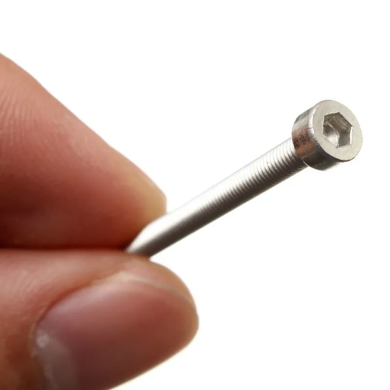 Follow the manufacturer’s guidelines for boss dimensions.
It’s suggested to use these with materials that are ductile, or have high elongation. Formlabs Nylon 11 Powder or Nylon 12 Powder are both suitable for this, as are the Tough and Durable Resins in the Formlabs SLA material family. Brittle materials, or those with low elongation (such as the Rigid Resins in the Formlabs SLA material family), may crack when used with self-tapping screws, so take caution and wear eye protection when using these materials.
Including threaded geometries in your printed part can be effective if you follow certain guidelines. Stick to larger thread sizes, at least ¼”–20 (imperial) or M6 (metric) or larger; reduce stress concentrations with fillets; and use thread profiles that are designed for plastics. For smaller screws, the threads should be customized to create a better fastener. For example, printing a semi-circular thread profile (on screw and nut) and using a 0.1 mm offset gives better thread engagement with improved wear characteristics.
SLA and SLS 3D printing are generally preferable for this method over FDM, because they are more precise and can create parts with a smoother surface finish. Any material with particularly low surface friction, such as Durable Resin, is less likely to show wear over multiple cycles of assembly and disassembly.
When preparing your part for printing, it's important to minimize support structures on any threaded surfaces to ensure your parts will come together smoothly without additional post-processing.
There are many options for combining multiple 3D printed components using screws and threaded fasteners. From directly 3D printing threads to using off the shelf inserts, you can choose any of the methods outlined above, based on the chosen material, the number of cycles of assembly and disassembly you anticipate, the strength required, and the amount of extra steps your workflow can accommodate.
Curious to see what 3D printing material might be right for your application? Use our interactive wizard to choose the best 3D printing material or request a free 3D printed sample part to see the quality firsthand.
Explore 3D Printing MaterialsRequest a Free Sample Part
How do you assemble 3D-printed parts? Practical tips on threads & screws for 3D printing
What are the ideal ways to assemble 3D-printed components? This article compares different methods for designing threads for 3D printing and provides step-by-step instructions on how to install screws and other fasteners.
Threaded fasteners, such as screws and inserts, are a popular method for securing 3D-printed parts together. Threaded fasteners allow quick assembly and disassembly, granted the threading has been designed and printed properly, and provide robust connectivity so parts don’t come apart easily.
This article covers the optimal threaded fastening techniques to apply when dealing with 3D-printed parts and examines the methodology behind implementing each of them.
To learn more about the different types of threads, especially if you're also interested in CNC machining custom parts, read our extensive guide to threads .
What are threaded fasteners for 3D printing?
As a rule of thumb the minimum wall thickness around a thread should match the diameter of the fastener (e.g. an M5 fastener requires a minimum of 5mm wall thickness around the threaded hole). If the wall thickness is too low, parts can bulge and distort due to the added stress and in some cases (particularly with FDM) delamination or fracturing can occur.
The table below introduces the threaded fastening methods that are best suited to 3D printing.
| Process | Description |
|---|---|
| Inserts | Popular method used regularly that gives a strong metal-on-metal connection but requires additional components and installation |
| __Embedded nut __ | Fast method for securing components. Accurate design and print are needed |
| Self-tapping screws | One-off method for securing parts that is not optimal for repeated disassembly |
| __Cutting threads __ | Provides design freedom however correct tapping procedure is important |
| __Printing threads __ | Not suited for small threads (less than M5) and requires high printer detail/resolution to print accurately |
Note: Drilling the pilot or alignment hole to the desired diameter post-printing, before implementing any of the fastening methods discussed in this article, will typically give a more accurate diameter compared to a 3D-printed hole.
What are inserts for 3D print assemblies?
The two types of inserts that are best suited for 3D printing are heat-set inserts and tap-in inserts. Inserts provide strong metal-on-metal contact and are very easy to install. An accurate pilot hole is required, so drilling is recommended before installation.
Methodology for heat-set inserts
-
Align the insert with the pre-printed or drilled hole (for hole sizes refer to the insert manufacturer's recommendations)
-
Insert a soldering iron into the insert, heating it and the surrounding material up (avoid overheating and melting the surrounding material)
-
Slowly apply pressure, pushing the insert down into the hole to the desired depth.
Methodology for tap-in inserts
-
Align the insert with the pre-printed or drilled hole (for hole sizes refer to the insert manufacturer's recommendations)
-
Using a hammer gently tap the insert down into the hole to the desired depth.
What is an embedded nut in 3D printing?
Another method of securing 3D printed components together is to embed a nut into the component via a nut-shaped cavity (often referred to as a nut boss). This method does not require any material removal. Often determining the optimal nut boss dimensions requires several iterations. Printing small test parts to determine the ideal dimensions can save on time and material costs.
Methodology for embedded nuts
-
Measure your nut. If you do not have access to the nut a quick internet search will reveal standard overall dimensions for both metric and imperial nuts.
-
Include the desired nut profile in your CAD model . An iterative process may be required to find the best nut clearance based on printer calibration. As a starting point a 0.2 mm offset around the nut (0.1 mm on each side) should give a loose fit. This also may need to be increased for nuts greater than M12.
-
Select the appropriate cut-out depth (typically just below flush).
-
Including a drop of superglue on the back side of the nut will help secure it in place.
What are self-tapping screws?
Self-tapping screws cut a thread into a pre-drilled hole as they are screwed down. This offers a quick assembly method but is not suited for applications where parts will regularly be assembled/disassembled. Special self-tapping screws for plastic can be used that limit the radial stress on 3D printed holes lowering the likelihood of bulging, delamination or fracturing occurring.
Methodology for self-tapping screws
-
3D print or drill a hole in the desired screw location. For optimal pilot hole size consult the self-tapping screw provider. A pilot hole size that provides 75% to 80% thread engagement is a good starting point if this information is difficult to come by.
-
Assemble components to be secured ensuring to correctly align all holes where the self-tapping screws will be used.
-
Slowly screw the self-tapping screw down into the hole, ensuring it remains perpendicular to the hole during fastening.
What is thread cutting (or cutting a thread) for 3D printing?
Thread cutting (more commonly known as tapping) involves using a tap wrench to cut a thread in a pre-printed or drilled hole. Threads are regularly cut in 3D printed plastics.
Methodology
-
3D print or drill a hole in the required location of the thread. For pilot hole (tap drill) sizes that correspond to each thread size refer here
-
Using the correct size tap wrench and ensuring it remains perpendicular to the hole, slowly cut the thread regularly reversing or “backing off” to remove excess material to avoid binding.
-
Avoid forcing the tap wrench as this can lead to fractures or splitting of the 3D printed material.
-
Continue tapping to the desired depth.
Insert your desired threaded fastener before assembly to ensure a clean fit.
Cutting a thread with a tap wrench3D printing threads for assembly
The process of 3D printing threads eliminates the need for any extra steps post printing and allows parts to quickly be assembled together. Limitations on printer accuracy and resolution will govern the success of a printed thread. Threads smaller than M5 printed via FDM should be avoided with one of the other threaded fastener methods discussed in this article implemented instead.
After printing the threaded fastener should be screwed and removed from the hole several times to clean the printed thread before final assembly.
Practical advice for threads, screws & more assembly methods for 3D printing
-
For a more accurate fastener pilot hole consider drilling the hole after printing rather than printing it in the part.

-
The minimum wall thickness around a thread should match the diameter of the fastener (e.g. an M5 fastener requires a minimum of 5mm wall thickness around the threaded hole).
-
Heat-up or tap-in inserts and embedded nuts are the most popular methods for securing 3D printed components due to their simple installation, connection strength (metal-on-metal) and ease of repeated assembly and disassembly.
Curious about the cost of prototyping with 3D printing?
Our online 3D printing services Upload a CAD file for a free, instant quote
Ready to transform your CAD file into a custom part? Upload your designs for a free, instant quote.
Get an instant quote3D printing - threads and screws
First things first: what is the difference between a screw and a thread?
A screw is a fastener used to form a connection that can later be dismantled, while the thread is the main fastener of the screw.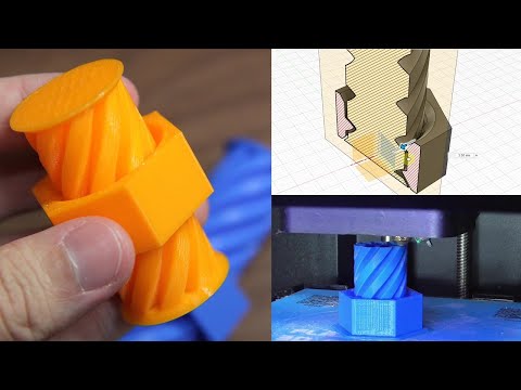 In this case, the thread is not only used for screws; they are also present on pipes, in linear drives, worm gears and many other devices.
All threads have in common the way they are formed. Each thread is a continuous spiral groove of a certain cross section, made on the outer or inner side of the cylindrical surface.
In most cases, the cross section or shape is triangular or trapezoidal. Triangular thread forms are primarily used for fasteners (screws), while trapezoidal thread forms, varieties of square threads, are used for power transmission and linear drives on lead screws. To keep things simple, this article only covers triangular shaped threads, but everything applies to both types.
A further level of categorization distinguishes metric threads from inch threads. The former are mainly used in Europe and Asia, while the latter are used in America and the UK. To the untrained eye, they look the same, but the difference exists in the shape of the triangle and the pitch of the spiral curve.
In this article, we will cover the basics of designing and 3D printing screws and threads.
Basic Terms
There are a few terms and concepts that you should be familiar with before you start designing a thread.
External or internal thread : external or external thread exits the cylindrical surface. The female thread is cut on the inner cylindrical surface. For example, bolts have external threads, while nuts have internal threads.
Thread axis : line through the center of the cylinder on which the thread is to be formed.
Base : the lower part of the groove that runs around the body of the thread.
Comb : The highest point of the thread profile.
Large diameter : The diameter of a cylinder enclosing the top of an external thread or the base of an internal thread. This cylinder is concentric with the axis of the thread.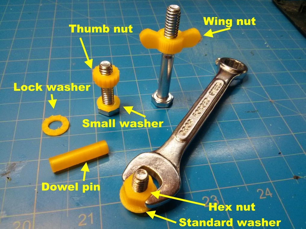
Minor Diameter : The diameter of a cylinder enclosing the root of a thread on an external thread or the crest of an internal thread. This cylinder is concentric to the thread axis and large diameter. The smaller diameter is also known as the drill diameter when handling internal threads.
Pitch : distance between equivalent points on adjacent threads. For example, the distance between two adjacent crests of a triangular thread.
Metric thread: The "M" designation of a metric thread indicates the nominal outside diameter of the thread in millimeters. For example, an M5 thread has a nominal outer diameter of 5 mm. For external threads, the nominal outside diameter is equivalent to the major diameter. For internal threads, the nominal outside diameter can be determined by measuring the minor diameter and referring to the metric thread table.
Inch threads: Inch threads are designated using a number of standards, including the Unified Thread Standard (UTS), which basically refers to standard thread sizes as numbers (eg #4).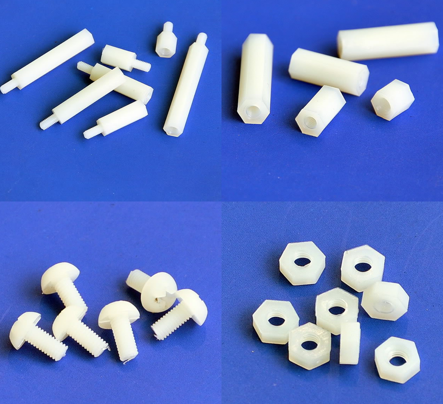 The two most important measurements in UTS are the major or minor diameter of external or internal threads, respectively, and threads per inch (TPI).
Thread Modeling
Let's look at the process of designing external and internal threads using Fusion 360, which provides a simplified threading feature.
Other CAD programs have tools with varying degrees of similarity. It is important to understand the basics presented in the previous section. With this knowledge, you will be able to use any available modeling tool for 3D modeling.
Let's start with the outer thread of the bolt.
External thread
- Draw a circle with a diameter equal to the largest diameter of the desired thread.
- Create a cylinder by extruding a circle to the desired thread length.
- Go to "Create" and select the "Thread" option.
- Select the newly created cylinder. Make sure "Modeled" is checked. Set the thread type and other thread options.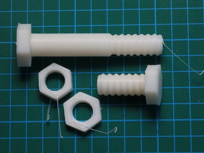 Click OK.
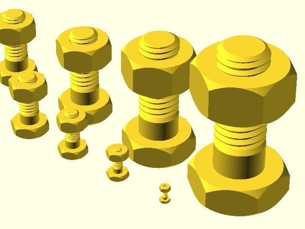
That's it. You have an external thread! To make a good bolt out of it, you need to attach it to the head to your liking.
Now let's create a nut with an internal thread.
Internal thread
- Create a hexagon. For the purposes of this tutorial, just make sure it's larger than the carving you want to create.
- Push it out to the desired height.
- Make a hole in the center by selecting the "Hole" option from the "Create" menu. The hole diameter must match the largest thread diameter.
- Select the inner surface of the newly created hole, go to "Create" and select the "Thread" option.
- Don't forget to check the "Modeled" option. Set the thread size and other parameters. Click OK.
That's it. Your first carvings are ready for 3D printing!
Tips for 3D Printing Threaded Parts
This may seem like a simple task at first glance, but printing threads is not always easy, especially if you need small diameters.
Assume you are using a 0.4 mm nozzle and a 0.2 mm layer height. With this setting, the smallest pitch you can achieve during 3D printing is likely to be around 0.5mm (give or take 0.1mm). This pitch is suitable for M3 threads and you should have no problem trying to print an internal thread on a relatively large part. This is because your threads will have enough time to cool while the nozzle is in a different location.
Things get interesting if you need an external thread, for example on a screw or bolt. In this case, the nozzle has nowhere else to go, which means that you will probably need additional cooling. Check your 3D printer before you decide to print a lot of thin external threads.
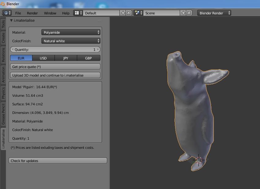
One of the most practical options before starting thread printing is the M10 3D Printed Thread Test. Thanks to this special 3D model, you will be able to check exactly what your 3D printer is capable of.
Settings when 3D printing parts with threads
Below are some general guidelines for setting up your 3D printer when printing threads.
- Make sure your 3D printer is properly calibrated. Extruder calibration is also important.
- Always try to print threads vertically. For best results, the thread axes should be perpendicular to your 3D printer table.
- Print without the calipers, or at least make sure they don't go inside the threads. Otherwise, removing them and maintaining functionality can be a real problem, especially with internal threads.
- If possible, use at least 4 vertical layers or vertical walls at least 2 mm thick. This will ensure the strength of the thread.
- Try to set the filling density to at least 25%.
- Layer height is an important parameter when 3D printing threads. For smooth operation, the layers should be as thin as possible. As a guideline, threads larger than M12 or 1/2" can be successfully printed at 0.2mm, while smaller threads should be printed at thinner layers.
Resume
Even if your first test fails, don't despair! Here are some final tips for 3D printing threads:
- Even if you manage to print beautiful external threads smaller than M6 (6mm in diameter), think twice before using it for heavy duty use.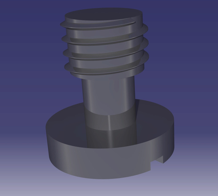 Due to the small diameter and the nature of 3D printing, this thread size is best suited for visual models only. If it must be a functional piece, consider a different design.
- Internal threads less than 4 mm in diameter have a small pitch, which makes 3D printing difficult. Consider printing a blank hole and tapping with a wrench that size. In any case, it's always a good idea to clean threads before use, whether it's 3D printing or trimming.
- Some materials shrink more than others. Before 3D printing large threaded parts, make some small samples to check the thread dimensions.
8mm pitch screws not good for precision printing?
Technical
Follow the author
Follow
Don't want
25
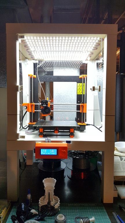
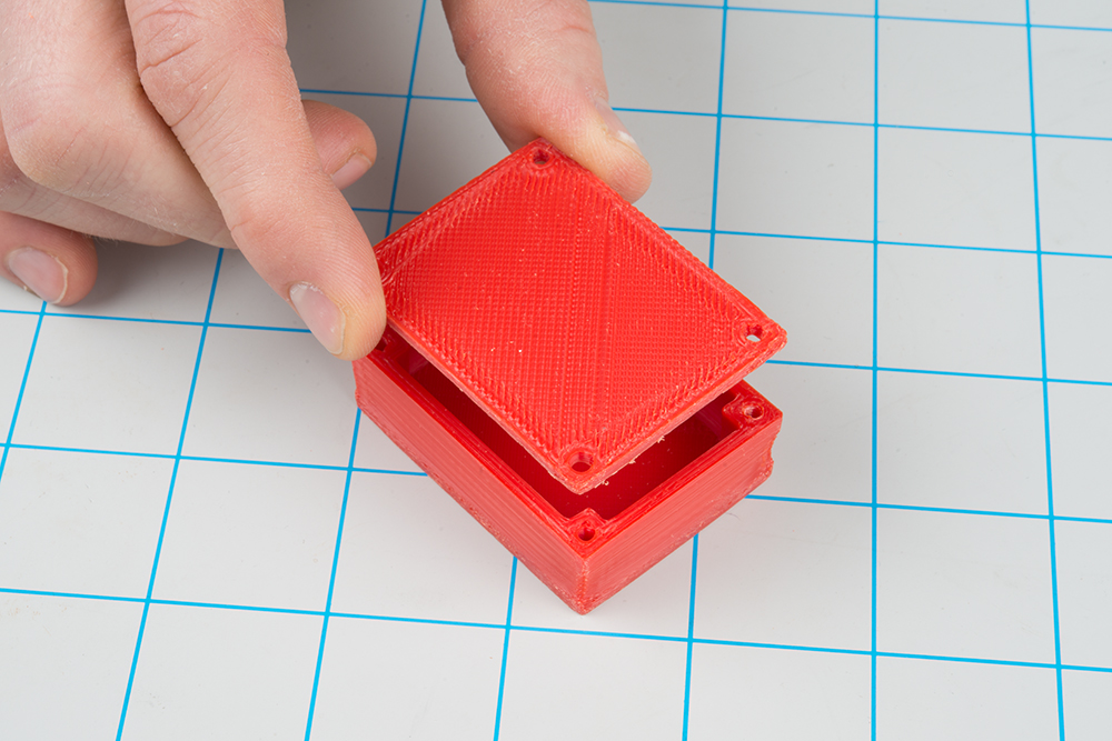
To start a photo with the final result.
Having assembled another H-bot printer, I decided to get confused with the print quality.
First of all, a surface defect was thrown in the form of randomly protruding layers.
Below in the photo is an example of the problem, visible only at a certain angle of incidence of light. The lack of repeatability of the problem said that it was not a matter of mechanics, if something had stuck, then there would probably have been a repeating pattern from instance to instance.
The photo shows the same G-code printed several times. the difference in layer thickness between the thinnest and the most protruding could reach 0.1 mm (broke the part and measured the size of the protrusions)
geared bmg, I tried a thermal barrier all-metal and with through teflon. I changed the coupling on the screw from flexible to rigid, put a spring-loaded nut.
In the end, nothing changed the surface quality appreciably.
Armed with a magnifying glass, I came to the conclusion that the problem is related to the floating Z height. I took a macro photo and moved a fragment of the picture in the editor. If the height of the layers were constant, the fragment would coincide with the main part, but I saw that the layers are different in thickness.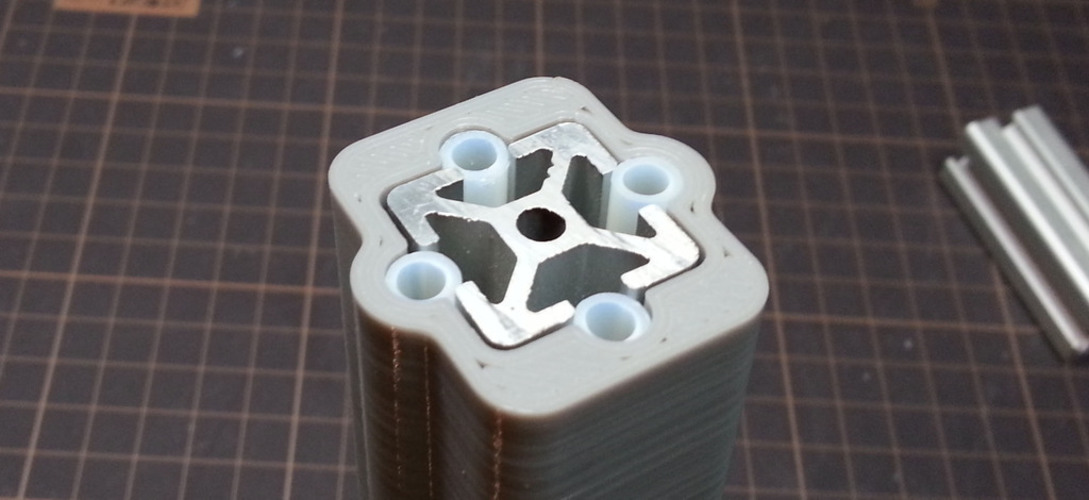
Some layers are a little thicker, some are a little thinner, but in the end the total height is always the same. For example, in the photo above you can see that after 6 too thick layers there are too thin layers and somewhere by the 8th layer the height returns to normal.
After calculating on the calculator, I realized that with a shaft of 8 mm I can not get the required layer height accuracy. It is generally accepted that steppers can clearly give steps only up to 1/8-1/16 microstep, with a microstep of 1/32 and then the accuracy does not increase.
That is, I could hope for a minimum height change of 0.04mm and, accordingly, the layer height should have been a multiple of these figures.
layer 0.16mm and 4 microsteps,
either 0.2mm and 5 microsteps,
or 0.24mm and 6 microsteps, and so on.
Having spit on useless experiments, I bought a screw with a pitch of 2 mm, changed it and printed the same G-code with the same 1/16 micropitch (of course I changed the number of steps per mm in the firmware).
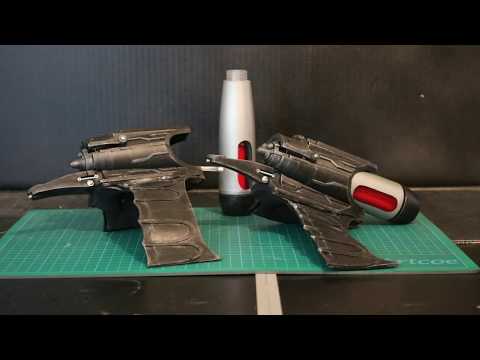
The result is as in the title picture.
Printed in vase mode. Photographed under a light bulb, at a certain angle, so that the defects are as clearly visible as possible.
On the left is a screw with a pitch of 8 mm, on the right is a screw with a pitch of 2 mm
I concluded for myself that a screw with a pitch of 8 mm on the Z axis is too much.
Z-axis ZAV defects screw
Subscribe to the author
Subscribe
Don't want
25
More interesting articles
Dmaw
Loading
25.10.2022
2102
12
Subscribe to the author
Subscribe
Don't want
This problem has been known for a long time, but I didn't know about it.