Artec eva 3d scanner price
3D Object Scanner Artec Eva
| Scanner type | Handheld | Handheld | Handheld | Handheld | Desktop |
| 3D point accuracy, up to | 0.1 mm | 0.1 mm | 0.05 mm | 0.1 mm | 0.01 mm |
| 3D resolution, up to | 0.2 mm | 0.5 mm | 0.1 mm | 0.2 mm | 0.029 mm |
| 3D accuracy over distance, up to | 0.1 mm + 0.3 mm/m | 0.1 mm + 0.3 mm/m | 0.05 mm + 0.3 mm/m | 0.1 mm + 0.3 mm/m | — |
| HD Mode | Yes | No | N/A | Yes | N/A |
| Hybrid geometry and texture tracking | Yes | No | Yes | Yes | N/A |
| Data processing algorithms | Geometry and texture based | Geometry based | Geometry and texture based | Geometry and texture based | Geometry based |
| Working distance | 0.4 – 1 m | 0. | 0.2 – 0.3 m | 0.35 – 1.2 m | — |
| Volume capture zone | 61,000 cm³ | 61,000 cm³ | 2,000 cm³ | 160,000 cm³ | 324 cm³ |
| Linear field of view, H×W @ closest range | 214 × 148 mm | 214 × 148 mm | 90 × 70 mm | 244 × 142 mm | — |
| Linear field of view, H×W @ furthest range | 536 × 371 mm | 536 × 371 mm | 180 × 140 mm | 838 × 488 mm | — |
| Angular field of view, H×W | 30 × 21° | 30 × 21° | 30 × 21° | 38.5 × 23° | — |
| Ability to capture texture | Yes | No | Yes | Yes | Yes |
| Texture resolution | 1.3 mp | — | 1.3 mp | 2.3 mp | 6.4 mp |
| Colors | 24 bpp | — | 24 bpp | 24 bpp | 24 bpp |
| 3D reconstruction rate for real-time fusion, up to | 16 fps | 16 fps | 7. 5 fps 5 fps | 22 fps | — |
| 3D reconstruction rate for 3D video recording, up to | 16 fps | 16 fps | 7.5 fps | 44 fps | — |
| 3D reconstruction rate for 3D video streaming, up to | — | — | — | 80 fps | — |
| Data acquisition speed, up to | 18 mln points/s | 2 mln points/s | 1 mln points/s | 35 mln points/s | 1 mln points/s |
| 3D exposure time | 0.0002 s | 0.0002 s | 0.0002 s | 0.0002 s | Customizable |
| 2D exposure time | 0.00035 s | 0.00035 s | 0.0002 s | 0.0002 s | Customizable |
| 3D light source | Flashbulb | Flashbulb | Blue LED | VCSEL | Blue LED |
| 2D light source | White 12 LED array | White 12 LED array | White 6 LED array | White 12 LED array | RGB LED |
| Position sensors | — | — | — | Built-in 9 DoF inertial system | — |
| Display/touchscreen | USB streaming through external computer | USB streaming through external computer | USB streaming through external computer | Integrated 5. 5" half HD, CTP. Optional Wi-Fi/Ethernet video streaming to external device 5" half HD, CTP. Optional Wi-Fi/Ethernet video streaming to external device | USB streaming through external computer |
| Multi-core processing | On external computer | On external computer | On external computer | Embedded processors: NVIDIA® Jetson™ TX2 Quad-core ARM® Cortex®-A57 MPCore Processor NVIDIA Maxwell™ 1 TFLOPS GPU with 256 NVIDIA® CUDA® Cores | On external computer |
| Interface | 1 × USB 2.0, USB 3.0 compatible | 1 × USB 2.0, USB 3.0 compatible | 1 × USB 2.0, USB 3.0 compatible | Wi-Fi, Ethernet, SD card | USB 3.0 |
| Internal hard drive | — | — | — | 512 GB SSD | — |
| Supported OS | Windows 7, 8 or 10 x64 | Windows 7, 8 or 10 x64 | Windows 7, 8 or 10 x64 | Scanning: No computer required Data processing: Windows 7, 8, 10 x 64 | Windows 10 x64 |
| Recommended computer requirements | Intel Core i7 or i9, 64+ GB RAM, NVIDIA GPU with 8+ GB VRAM, CUDA 6. 0+ 0+ | Intel Core i7 or i9, 32 GB RAM, GPU with 2 GB VRAM | Intel Core i7 or i9, 32 GB RAM, GPU with 2 GB VRAM | Intel Core i7 or i9, 64+ GB RAM, NVIDIA GPU with 8+ GB VRAM, CUDA 6.0+ | Intel Core i7 or i9, 64+ GB RAM, NVIDIA GPU with at least 3 GB VRAM, CUDA 3.5+ |
| Minimum computer requirements | HD: Intel Core i7 or i9, 32 GB RAM, NVIDIA GPU with CUDA 6.0+ and at least 2 GB VRAM SD: Intel Core i5, i7 or i9, 12 GB RAM, GPU with 2 GB VRAM | Intel Core i5, i7 or i9, 12 GB RAM, GPU with 2 GB VRAM | Intel Core i5, i7 or i9, 18 GB RAM, GPU with 2 GB VRAM | HD: Intel Core i7 or i9, 32 GB RAM, NVIDIA GPU with CUDA 6.0+ and at least 4 GB VRAM SD: Intel Core i5, i7 or i9, 32 GB RAM, GPU with 2 GB VRAMA computer is needed only for data processing. Scanning does not require a computer. | Intel Core i5, i7 or i9, 32GB RAM, GPU with 2 GB VRAM |
| 3D mesh | OBJ, PLY, WRL, STL, AOP, ASC, PTX, E57, XYZRGB |
| CAD | STEP, IGES, X_T |
| Measurements | CSV, DXF, XML |
| Power source | AC power or external battery pack | AC power or external battery pack | AC power or external battery pack | Built-in exchangeable battery, optional AC power | AC power |
| Dimensions, H×D×W | 262 × 158 × 63 mm | 262 × 158 × 63 mm | 190 × 140 × 130 mm | 231 × 162 × 230 mm | 290 × 290 × 340 mm |
| Weight | 0. 9 kg / 2 lb 9 kg / 2 lb | 0.9 kg / 2 lb | 0.8 kg / 1.8 lb | 2.6 kg / 5.7 lb | 12 kg / 26.7 lb |
Buy Handheld 3D Scanners and 3D Scanning Software at Best Price
Artec Leo Premium Pack
Ultimate 3D scanning pack that has everything you need: top-level handheld scanner, Calibration Kit, extended warranty, maintenance, software subscription, and then some.
Artec Leo
Our best 3D scanner, equipped with wireless technology and an inbuilt touch screen
Artec Eva
The ideal 3D scanning solution for making quick and accurate 3D models of medium-sized objects
Artec Space Spider
A metrological 3D solution, perfect for capturing small objects for CAD applications and more
Artec Eva Lite
Entry level white light 3D scanner. Geometry tracking and capture only.
Artec Ray
Long range laser scanner for digitizing large objects, such as airplanes or buildings.
Artec Micro
The perfect metrology-grade desktop 3D scanner for quality inspection, jewelry and dentistry.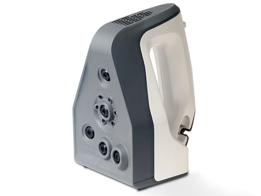
Artec Metrology Kit: Entry
Optical coordinate measuring system for inspection and engineering. Accuracy up to 4 microns.
Artec Metrology Kit: Professional
Optical coordinate measuring system for inspection and engineering. Accuracy up to 4 microns.
Upgrade Eva Lite to Eva
Get the full power of Eva’s color tracking and capture features.
Leo + Space Spider
A combo of our powerful 3D scanners. Ideal detailed capture of multiple objects.
Space Spider + Eva
Duo of professional 3D tools available at a special discounted price
Special offers
Educational packages
Artec handheld 3D scanners available at lower prices for classroom use
View more info
Geomagic Design X bundle
An all-in-one reverse engineering solution with Artec Studio and 3D engineering software
View more info
Geomagic for SOLIDWORKS bundles
Export your 3D scans directly to SOLIDWORKS and make manufacture-ready 3D models
View more info
Geomagic Freeform bundles
A winning combination for hands-on organic product design and manufacturing
View more info
Geomagic Control X bundles
An outstanding combo for extensive quality control with easy data capture and analysis
View more info
Geomagic Wrap bundles
A great solution for comprehensive exact surfacing with an extensive toolbox
View more info
Artec software
Artec Studio 17 Trial
An easy way to get started.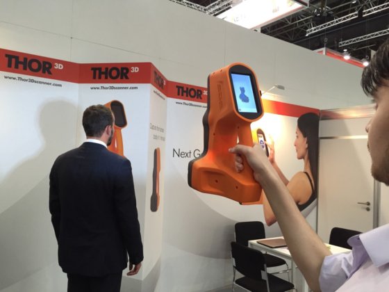 Try Artec Studio for 30 days at no cost.
See all plans
Free download
Artec Cloud
Annual, renewed automatically every year
See all plans
200 GB
12 months from date of payment
See all plans
12 months from date of payment
See all plans
Geomagic software
Geomagic for SOLIDWORKS
An ideal scan-to-CAD solution for a seamless workflow in SOLIDWORKS.
Geomagic Design X
Optimal reverse engineering software for fast conversion of 3D scan data into CAD models.
Geomagic Control X Professional
A powerful metrology solution with an advanced set of tools for a flexible workflow.
Geomagic Wrap
A versatile solution with an extensive toolbox, perfect for exact surfacing.
Optional equipment
Leo Calibration Kit
Pre-order yours today! Recalibrate your 2022 Artec Leo in your own time, and in your own environment, to ensure its accuracy always stays at its highest.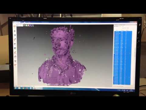
{{ getPrice() | formatPrice }}
Add to cartWhere to buy
Artec Turntable
A smart turntable for effortless 3D scanning of small objects with Artec Space Spider.
{{ getPrice() | formatPrice }}
Add to cartWhere to buy
Smart battery charger (Leo)
High-performance and intelligently designed to deliver maximum charges, while extending battery lifespan to the fullest.
{{ getPrice() | formatPrice }}
Add to cartWhere to buy
Eva/Spider battery pack
Scan anywhere for up to 6 hours non-stop. Includes a pouch, a charger, and a power cable for connecting the battery to the 3D scanner.
{{ getPrice() | formatPrice }}
Add to cartWhere to buy
Artec Eva hard case
Designed with Eva’s measurements in mind, this hard case will keep it safe during storage and transportation.
{{ getPrice() | formatPrice }}
Add to cartWhere to buy
Space Spider calibration kit
This kit is there to make sure the accuracy of your Space Spider remains at its highest at all times, even after a sudden jolt!
{{ getPrice() | formatPrice }}
Add to cartWhere to buy
Battery pack cable
Got a field scanning job lined up but your dog has chewed the cable of your Eva/Space Spider battery pack? Order a replacement in just a few clicks!
{{ getPrice() | formatPrice }}
Add to cartWhere to buy
Power supply for battery pack
No matter what extra accessory you may need, Artec 3D has you covered.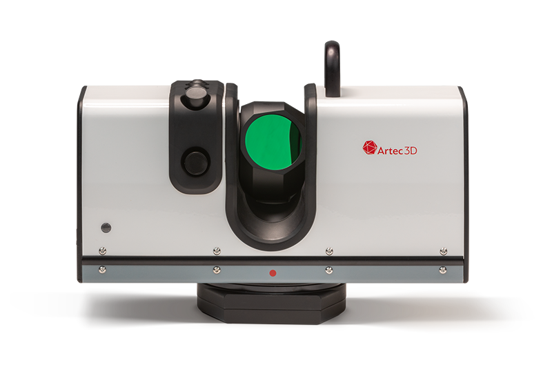 Order this native power supply unit to charge your Eva/Space Spider battery pack the fastest and safest way possible!
{{ getPrice() | formatPrice }}
Add to cartWhere to buy
Eva/Spider USB cable
A fully tested cable featuring the connector needed for your Artec scanner.
{{ getPrice() | formatPrice }}
Add to cartWhere to buy
Eva/Spider power supply
1.8 m power supply developed exclusively for Artec 3D scanners for stable performance
{{ getPrice() | formatPrice }}
Add to cartWhere to buy
Artec USB Kit
Maximize your Artec Eva or Space Spider’s FPS rate with a USB 3.1 to Thunderbolt 3 adapter and add a 5 m extension to your scanner’s USB cord for scanning over longer distances.
{{ getPrice() | formatPrice }}
Add to cartWhere to buy
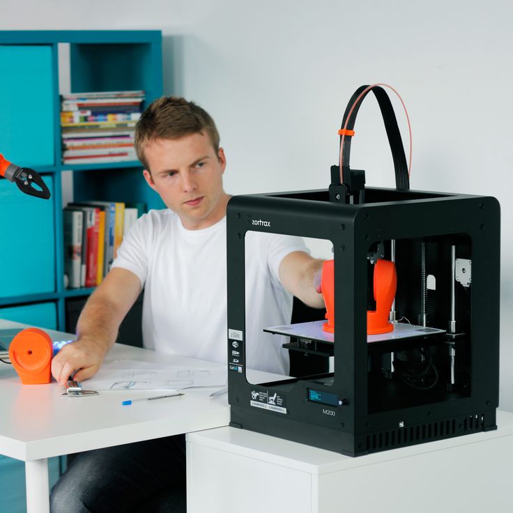
3D SCANNER Artec Eva™ - 3D Smartprint
The Artec™ Eva Scanner is the ideal choice for those who need to scan an object in seconds in color and with high accuracy. Eva does not need any markers or additional calibration. With its high frame rate and the ability to acquire high-resolution color data, the scanner has almost unlimited possibilities.
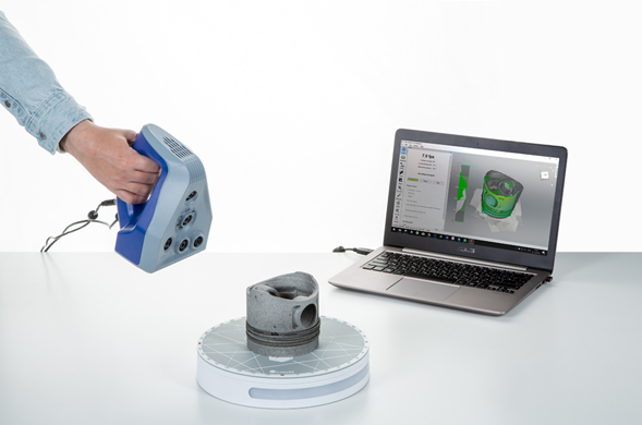
The Artec™ Eva 3D Scanner is like a video camera that captures images in 3D. The scanner captures up to 16 frames per second, automatically aligning them in real time. The ability to scan quickly and easily is especially important for special effects, medical and biomechanical research. Due to their high quality, color models produced with Eva can be used in industries such as computer graphics and animation, forensics and medicine.
How it works
Scanning
1. Start scanning
Aim the scanner at the object and press the button. The scanning process will start immediately. It's very simple. If something goes wrong during the scanning process, the system will tell you about it using on-screen prompts, as well as a special sound signal.
http://www.artec3d.com/images/howitworks/eva_dino_howitworks_1.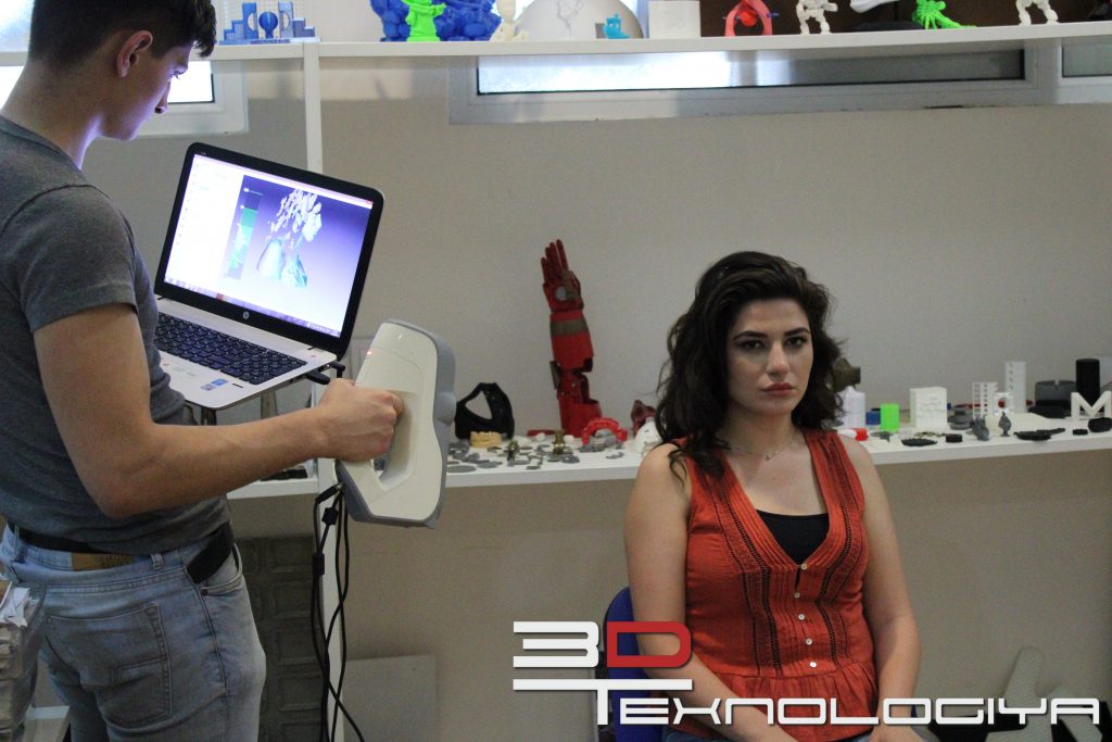 jpg
jpg
2. Moving the scanner around the object
Move the scanner around the object. On the computer screen in real time you will see what has already been scanned and what still needs to be scanned. If you can't get an image of a particular part of the object right away, don't worry, you can come back to it later.
http://www.artec3d.com/images/howitworks/eva_dino_howitworks_2.jpg
3. Optimal number of scans
Scan the object as many times as necessary to obtain an image of the entire object. If you need to move an object to digitize all of its parts, scan one side first, then turn off the scanner, turn the object over and scan the other side.
http://www.artec3d.com/images/howitworks/eva_dino_howitworks_3.jpg
Processing
1. Scan Alignment
Align the scans to get a single image of the model. In case some part was missed, just scan it. For best results, after aligning the scans, process them using the global optimization algorithm.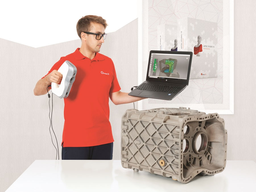
http://www.artec3d.com/images/howitworks/dino/spider_dino_howitworks_4.jpg
2. Merging scans into one 3D model
Join the scans together to get one triangulated mesh. Our gluing algorithm will quickly cope with this procedure.
http://www.artec3d.com/images/howitworks/dino/spider_dino_howitworks_5.jpg
3. Smoothing and optimization
You can optimize the mesh, seal holes and smooth the surface. Various tools in our software will help you deal with this.
http://www.artec3d.com/images/howitworks/dino/spider_dino_howitworks_6.jpg
4. Texturing
Apply a texture to an object with a single mouse click.
http://www.artec3d.com/images/howitworks/dino/spider_dino_howitworks_7.jpg
| Capable texture | yes |
|---|---|
| 3D resolution, up to | 0.5 mm |
| Accuracy, up to | 0.1 mm |
| Distance dependent accuracy up to | 0. |
| Texture camera resolution | 1.3 MP |
| Color | 24 bits per pixel |
| Light source | flash lamp (not laser) |
| Working distance | 0.4 - 1 m |
| Linear near field of view, HxW | 214 x 148 mm |
| Long distance linear field of view, HxW | 536 x 371 mm |
| Angular field of view, HxW | 30×21° |
| Video recording frequency, up to | 16 fps |
| Exposure time | 0.0002 s |
| Acquisition rate, up to | 2,000,000 points/s |
| Multi-core processing | Yes |
| Dimensions, HxDxW | 261.5 x 158.2 x 63.7 mm |
| Weight | 0. |
| Energy consumption | 12 V, 48 W |
| Interface | 1x USB2.0 |
| 3D model export format | OBJ, PLY, WRL, STL, AOP, ASCII, PTX, E57, XYZRGB |
| Measurement export format | CSV, DXF, XML |
| Capacity | 40'000'000 polygons per 1GB RAM |
| Supported OS | Windows 7 or Windows 8 - x64 |
| Minimum computer requirements | I5 or I7, 8-12Gb RAM, NVIDIA GeForce 400 series |
| Calibration | not required |
 03% per 100 cm
  85 kg
85 kg Only registered customers who have purchased this item can post reviews.
Artec
3D scanners3D scanning using the Eva
model as an example We have already got acquainted with the Artec Studio program ourselves and introduced the readers, and now we have become the owners of the Artec Eva 3D scanner (albeit for a while).![]() The second Spider model currently in production is based on the same principles, but has a number of design differences to achieve greater accuracy.
The second Spider model currently in production is based on the same principles, but has a number of design differences to achieve greater accuracy.
But before proceeding to a detailed description, let's make a short digression into the technology of 3D scanning.
Some general information
To obtain a mathematical model of an object, that is, its three-dimensional image in electronic form, we need to “feel” the object in one way or another and transfer the result to a computer processing program.
Contact scanners
You can literally feel with a mechanical probe, which is available in contact scanners. The probe, equipped with a touch sensor, moves and measures the height or depth of the object at each point of the coordinate grid specified from the control program. The carriage mechanism and service program may also allow for angular movements/calculations to account for cavities or holes in the object.
It is clear that the model will more accurately match the original object, the smaller the grid step, but the scanning time will increase proportionally, which for large and rather complex objects can be calculated for many hours and even several days.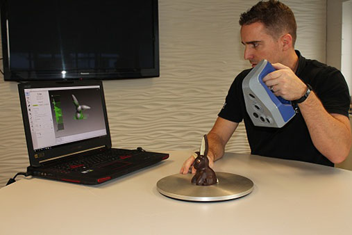
To some extent, the process can be speeded up programmatically by automatically detecting the complexity of the terrain and changing the grid step accordingly: for complex areas, reduce, increasing accuracy, for simple areas, increase, reducing time. But it will still not work to complete the scan in a few minutes instead of several hours or a day.
However, in some cases, you can wait to achieve the goal, but there are more significant limitations associated with the design features. It is clear that the probe must move along three axes with the help of some kind of drive, and if the minimum step of this drive, which determines the accuracy, can be made sufficiently small along any of the axes (tens of micrometers), then the limiting movement cannot be very large, before just because then the scanner itself will have the same dimensions. Two meters at least along two axes can still be realized, and there are such examples; 2.5–3 meters along each axis is already more difficult, including because a cube with a side of three meters can not be placed in every room.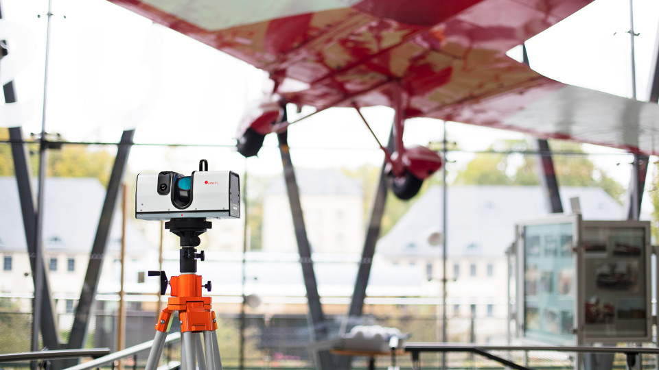 Therefore, such devices are most often used to scan objects that are large in two axes and much smaller in the third, such as bas-reliefs.
In addition to the size, the limited applicability of such scanners is associated with the presence of mechanical contact: the object being scanned must be sufficiently hard, durable and, of course, remain motionless not only for a long time, but also when touching the probe, that is, small light objects will have to be then fix, but this is not always possible. In addition, the object will have to be placed in the working volume of the scanner - it is difficult to imagine a design capable of driving a probe along the same bas-relief located high on the wall of a building.
Finally, we can only talk about the digitization of geometry, of course, a contact scanner will not be able to fix any color textures.
However, this technology has a positive side: an engraving or engraving-milling machine can be quite easily turned into a contact scanner, and the price of the machine + scanner combine will be slightly higher than that of the machine itself. True, the availability of advanced software for working with 3D models can give a noticeable increase in cost, but this is quite a common situation.
Non-contact scanners
Much more versatile and, of course, more compact are non-contact scanners, which, instead of mechanical contact, perceive reflections of some kind of radiation from an object. Moreover, they may well reproduce not only the shape, but also the color of the surface.
Since the scanned objects are usually located in places where there is lighting - natural or artificial, it is quite logical to use the reflection of the available light in the visible range of the spectrum. Passive 3D scanners are based on this, which are, in essence, a specialized version of a familiar video camera. However, the lighting that is quite acceptable for shooting a movie may not be enough to accurately reproduce the details when scanning, moreover, the object is usually unevenly lit. Of course, you can use special illuminators such as those used in photo studios, but this is not cheap, and most importantly, both compactness and mobility are lost.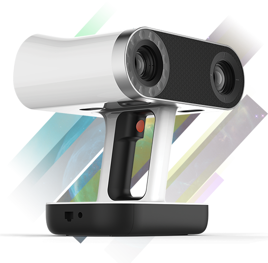
Therefore, most non-contact scanners have their own source of radiation, even the cheap Kinect sensor we reviewed in the previous review has its own infrared emitter.
In addition to infrared, other sources of radiation, up to ultrasonic, can be used: a long time ago well-known echo sounder used to study the topography of the bottom of reservoirs, also a 3D scanner of its kind. But, of course, the resolution will depend on:
- the propagation speed of the emitted waves, which will determine the maximum number of samples per unit time;
- wavelengths: to distinguish the details of the object, the dimensions of which are comparable to the wavelength, simply will not work.
For ultrasonic vibrations, these parameters are sufficient to determine the relief of the bottom of a lake or river, where it is not necessary to distinguish between millimeters and centimeters. But to scan objects or even small areas of the earth's surface, a shorter wavelength will also be required (the length of ultrasonic vibrations with a frequency of 40 kHz in air is 8 mm), and radiation should propagate faster - remember that in air the speed of sound is almost five times less than in water, and is approximately 330 m / s, that is, with a distance to the object of tens of centimeters and meters, we will be able to make only a few hundred measurements per second, having received information about only a few hundred points.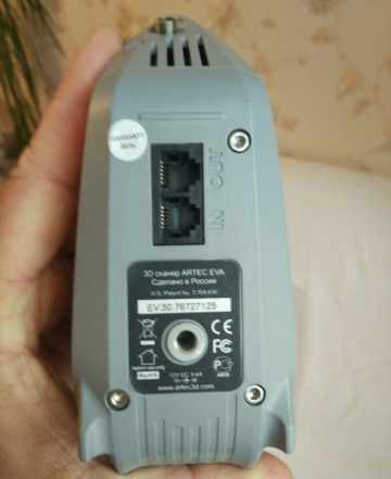
Therefore, laser emitters are often used. The speed of light is enormous, and many tens and even hundreds of thousands of measurements can be made per unit time, and the wavelength of a semiconductor laser usually does not exceed a micrometer.
Two methods are possible here; one is similar to echolocation - the distance is calculated from the time it takes for the laser beam to travel to the point and back. Such scanners can be used from a very long distance, but their resolution is limited by the accuracy of calculating the time interval: it takes a little more than three picoseconds (3 10 −12 s). It is very difficult to make accurate measurements of values of this order, and therefore very expensive, so you have to sacrifice resolution, which determines the scope of devices based on this principle: scanning large objects like buildings, for which a few extra millimeters do not play a special role.
Much better accuracy can be achieved by using the triangulation method, a term that GPS users have probably heard. With regard to scanners, this means the following: the emitter and the camera on the body are separated, and the beam is sent at a certain angle relative to the camera. Thus, a triangle is obtained, the base of which is formed by the emitter and the camera, and the apex is a point on the surface of the object. Based on the offset of the reflection formed by the lens on the camera sensor from this point, it is possible to calculate the angle between the incident and reflected rays; knowing the angle and length of the base, you can very accurately calculate the distance to the point of the object. True, such a technique works well only at relatively short distances, much shorter than when measuring by the beam transit time.
To speed up the process, a stripe is often used instead of a dot, but there is another method - the use of structured illumination, when the radiation source applies a grid to the object, not a dot or a stripe. A camera located slightly away from such a projector perceives the reflection of this grid and, from the detected distortions, calculates the distance to each point in the field of view. Due to this, both high speed (you can analyze the entire field of view at once) and better accuracy are achieved. This is the method used in Artec scanners.
The easiest way to use visible light emitters - laser or LED. However, they cannot be used to capture photorealistic color textures, so if the scanner has a texture camera, it either, like in Kinect, uses the light available in the room (but it may not be enough, and besides, subsequent color correction will most often be required), or has its own light source, unrelated to the one used to define the geometry of the object.
Parameters of Artec 3D scanners
We present the specifications of Artec 3D scanners declared by the manufacturer in the table.
| Artec EVA | Artec Spider | |
| Working distance, m | 0.4 - 1.0 | 0.3 |
| Line field of Visit W, mm): | ||
| at close range | 214 × 148 | 90 × 70 |
| at a long distance | 536 × 371 | 180 × 140 |
| The angular field of view (B × W, degrees) | 30 × 21 | |
Frequency Frequency.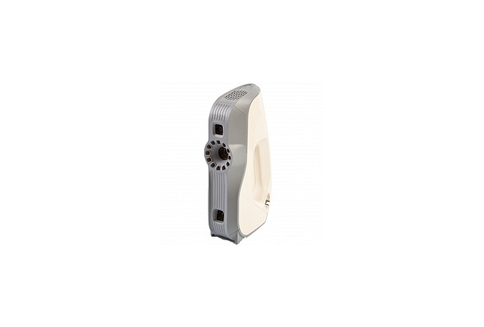 16 16 | to 7.5 | |
| Exhibit time, with | 0.0002 | 0.0005 |
| Data collection speed, points/s | to 200000005550 to 100000053 | 3D, mm | to 0.5 | to 0.1 |
| accuracy, mm | to 0.1 | to 0.05 |
| Light source | LAMP-rush (not laser) | Blue diode blue diode (not laser) |
| The possibility of shooting texture | Yes | |
| Resolution of the texture chamber | 1.3 MP | |
| Color | 24 bits per pixel | |
| GABARITA (B. , mm: | 262 × 158 × 64 | |
| Retail price indicated on the manufacturer’s website | € 13 700 | € 15 700 |
| ¹ - excluding connected cables and connectors | ||
We note that there is another EVA Lite model, different from EVA.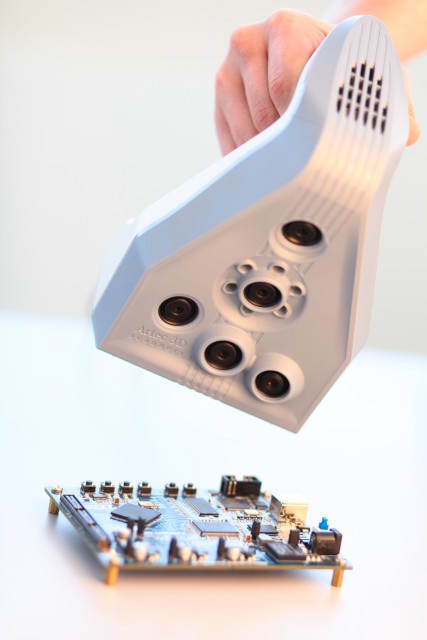 lack of a texture camera; its price is almost 30% lower - €9700, but there is only one base, and the owner of Eva Lite, having saved up some money, will be able to upgrade to Eva. True, you won’t be able to save money: the upgrade will cost exactly the difference between the prices of Eva and Eva Lite.
Some parameters require comments.
Resolution in 3D - the minimum size of an object that the scanner is able to distinguish, or the minimum distance between two elements of an object at which they are recognized separately.
Accuracy: An error detected by scanning a reference sample whose size is known to an accuracy of plus or minus 20 micrometers (according to the VDI2634 standard). The procedure is carried out for each copy of the scanner, and a certificate is included in the kit, which indicates the measurement results. And the table shows the maximum value for this type of scanner.
Consumption - of course, the given value is the maximum power consumption in the mode when all scanner mechanisms are used, including the backlight of the texture camera. The average consumption during actual operation, of course, will be noticeably less. When powered by AC power through a standard adapter, this does not matter, but when working "in the field", when the scanner is powered by some kind of battery, battery life is a very important factor.
Appearance, working parts
Scanners are shaped like a small iron: soleplate, easy-to-grip handle with buttons and outgoing cables (there are two of them: interface and power), base for installation on a table or other plane when not in use.
This iron is plastic and very light: the weight of the device is only 0.85 kg (excluding cables), so even a woman's hand can manipulate it.
Cameras and lighting organs are placed on the sole.
In the center is a color texture chamber surrounded by twelve white LEDs. In the lower part there is a 3D camera, in the upper part there is a flash (or projector) of structured illumination for recording geometry, also with white radiation.
Spider also has a texture camera in the center, only there are six smaller LEDs (obviously, this is due to the reduced range of working distances). But there are as many as three 3D cameras, and with increased resolution, due to which a greater scanning resolution is achieved. There is only one flash (projector) of structured illumination; it uses a blue glow diode.
At the top of the Eva is a ventilation grille that exposes a small fan that draws air into the case. It starts to rotate immediately after turning on the power, but its speed depends on the temperature inside the case, that is, on the mode of operation. When scanning, the noise becomes quite noticeable: we measured at a distance of 0.5 meters, simulating the distance to the head of the operator who holds the scanner in his hand, and our sound level meter showed 51.5-51.7 dBA. In an office space where several people are actively working, such noise will not be very noticeable even to the operator. In a quieter room, the situation is different, especially when you consider that when scanning, constant clicking is added to the sounds from the fan, accompanying the backlight on and off at the frame rate of the shooting; however, even here the volume cannot be called annoying, perhaps not very comfortable.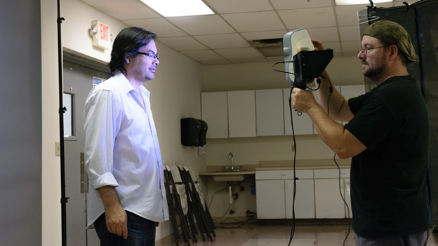
There are two things associated with the fan. Firstly, do not turn off the power of the scanner immediately after scanning is completed - its “offal” is still quite hot; you should wait until the fan speed drops to a minimum. Secondly, of course, along with the airflow created by the fan, dust will inevitably get inside the scanner, so you should avoid using Eva in dusty places.
Spider also has a grille at the top, but without a fan. Apparently, a significantly smaller number of backlight LEDs, along with a reduced maximum frame rate when shooting, do not create such significant heating inside the case as in Eva.
Both models are controlled by three-position rocker buttons, which differ in form, but not in functionality. They not only switch the scanner to one mode or another, but also control the Artec Studio program: a single click on Play/Pause will open the program’s Capture panel and start the preview mode, subsequent clicks switch both the scanner and the program from the Record mode to Preview and back. Clicking on "Stop" during the shooting will stop the process, and pressing twice will also close the "Shooting" panel in the program.
I must say that we just lacked such buttons when we worked with the Kinect sensor when writing the previous review. But Artec scanners could use one more button - power off, especially Eva with its constantly running fan. This would allow extending the battery life when powered by an optional battery (we will talk about it below), and for Eva it would be easy to make the action of such a button dependent on temperature and turn off the power only after the fan switches to a lower speed.
There is also an LED indicator, color and mode of illumination (steady/blinking) indicating the current mode. We will not list in detail - the possible states of the indicator are described in the Artec Studio user manual.
The base of the scanner has a threaded hole that allows the device to be mounted on standard photo tripods.
Eva also has RJ-12 6P6C connectors, which are quite unexpected for a 3D scanner, marked as In and Out. They are designed to synchronize multiple scanners when they work together using a 4-wire cable. The connection method is also described in the manual.
Equipment, options
Now about the equipment, which may differ slightly in different regions - first a brief listing, then details.
Scanners are always supplied with two interface cables (one spare) and an external power supply, the socket of which corresponds to the type accepted in the region of delivery.
Spider includes a calibration kit.
The scanners come in a well-printed quality cardboard box with a carrying handle. True, we got a test sample without packaging, so we cannot provide photos and judge by the materials that are on the Internet. In Russia, scanners come with bags similar to those used for photographic equipment, but a client who wants to save money can refuse such a bag. In other countries, Spider scanners are supplied in hard cases, Eva - in boxes.
The shape of the power supply is familiar from countless laptops and netbooks, providing 12V output up to 5A.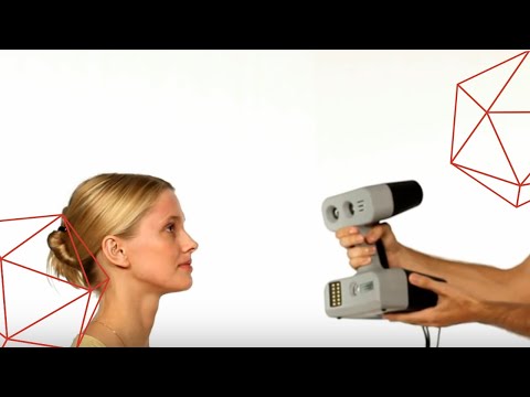 the output cable is longer - 1.95 m, it is connected to the scanner with a connector equipped with a union nut for reliability. Near this connector there is a ferrite ring to suppress RF interference.
The standard 2.9 meter USB 2.0 interface cable is also equipped with ferrite rings, but at each end. It connects to the scanner with a Mini-USB connector, which has an L-shaped shape.
The port for it is in a recess - this not only allowed the connector to fit into the dimensions of the scanner, but also prevented it from falling out from an accidental jerk (unless, of course, the jerk is too strong).
Optional 16000 mAh battery (59.2 Wh to be exact) is available. Of course, this is not Artec's own development: readers of our Power Supply section are already familiar with such models, however, for Artec, the battery is equipped with a convenient case fastened to a waist belt, but most importantly, a connecting cable with a rather specific connector.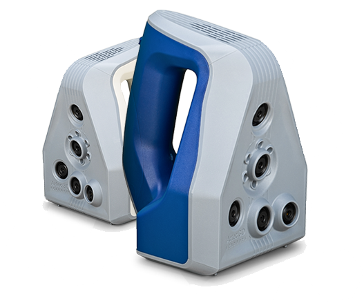 Unfortunately, the price of such a battery is very high, but this is a common situation for any options offered by the manufacturer of any device.
You can purchase either a hard case or a soft bag to transport the Eva scanner, which came in a regular carton. The prices for them are also not the most humane, especially for a case. We got the bag, although it is somewhat different than shown on the manufacturer's website, and we can say that it is quite convenient: there are several internal and external pockets, a shoulder strap and the possibility of attaching it to a belt. This bag will fit the scanner itself with cables, and the AC adapter, and there will be room for an optional battery.
The price of an additional USB cable is more or less adequate (in case two complete ones are not enough) - of course, if you do not compare with penny USB cables, which only the slowest devices can work with.
There may be situations when the standard USB cable may not be long enough, and the idea of using extension cords comes up. You can try, but no problems are guaranteed. The main thing: the extension cord should not be cheap, of which there are plenty on sale; the cable used in it must be no worse than in the "native" cable - Shielded High Speed USB 2.0, section 28AWG / 1P + 24AWG / 2C. Here, the first designation 28AWG / 1P defines the wires in the twisted pair of the Data line - the smaller the value, the larger the cross section and the longer the length can be if there are no problems; the second designation 24AWG / 2C defines the wires in the Power line, and therefore it is not so critical for a scanner powered by its own power supply. Of course, this extension should not be too long, and the presence of ferrite rings at its ends is also very desirable.
Installing the Artec Eva 3D scanner
Having unpacked the scanner, we connect the cables to it - the interface cable, correctly laying it in the recess, and the power supply (we fix it with a union nut). We connect the power supply to a 220 V socket, and the USB connector to the USB 2.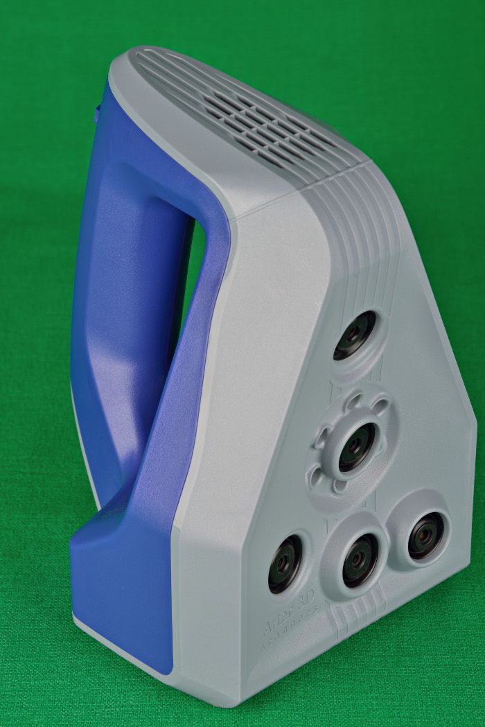 0 port of the computer. We wait until the system informs about the completion of the installation of drivers (they are included in the Artec Studio distribution kit), after which Artec 3D Camera and Artec Color Camera should appear in the device manager.
But after that, the scanner is not ready to work yet, it must first be activated (for us, who received the scanner for a while, the term changes to “rent”). To do this, launch Artec Installation Center (AIC), which is also installed with Artec Studio; in its "Scanners" window, a line appears with the name "Artec Scanner EV" (for Eva), followed by a serial number - it can be compared with the one on the base of the scanner (in the test copy it is written by hand, printed on commercial samples).
We make sure that the computer is connected to the Internet, and press the button "Activate ( we have Rent )" at the end of the line. After a few seconds, the button is replaced by the inscription “Activated ( Rented )”:
Unlike the program itself, activating the scanner does not mean it is linked to a specific computer, but only to an account on my. artec3d.com . If you need to use the scanner on another computer (where, of course, Artec Studio must be installed), then this can be done, just run AIC on it.
That's it, you can start working - the scanner should appear in the Artec Studio program. If it is supposed to scan on a computer that is not connected to the Internet for security reasons, then offline activation is also possible, which we talked about in the previous review.
Recall: in "Settings - Survey" for all scanners, except for Spider, not the model name is displayed, but the type in accordance with the coverage area; so, for Eva we will see "Scanner Type M".
And this is not just a line indicating the presence of a certain scanner: at the same time, the optimal processing algorithms for it are selected, the limit values of some adjustment ranges are set, and the possibility of setting certain parameters appears or, conversely, disappears. For example, for Eva, unlike Kinect, in the settings of shooting parameters it becomes possible to set the brightness of the texture, adjust the sensitivity and turn off the flash, and the frame rate (or scan speed) can no longer be set above 15 frames per second.
Correction and calibration
If the scanner was subjected to shocks and shaking during transportation, you can start by checking: it is enough to point the scanner at a right angle at a light, even, uniform surface (wall, floor, tabletop) from a distance within the operating range, and not in the near or far zone - for Eva it is 60–80 cm, and in the preview mode of Artec Studio, evaluate the geometry of the rectangle observed in the 3D view window. Of course, it is unlikely to be ideal, but if its shape is approximately the same as in the right screenshot, then everything is in order, and the presence of distortions in the left screenshot indicates the need for correction.
Correction is performed using the Diagnostic Tool installed with Artec Studio. Its use is described in detail in the manual, so we will not dwell on this, and will only say that for Eva the procedure is quite simple.
The only remark is that for some reason the utility's interface is not fully Russified; We hope that this phenomenon is temporary, and in subsequent versions all messages in it will be in Russian.
If you cannot achieve an acceptable result using the utility, you will have to contact the service center.
Scanning
A few general notes
Despite the small weight of the scanner, it is not very comfortable to hold it in a high or horizontally outstretched hand for a long time, for example, try holding a liter milk carton in this position yourself. Therefore, it is better to choose the location of the object so that it is approximately at the level of the operator’s stomach or chest in height, and horizontally separated from it by a distance within the limits indicated in the table plus the length of the half-bent arm. Actually, the operator himself will quickly understand all this from personal experience.
When shooting, avoid fast movements, even if it is just a 90-degree rotation of the scanner around the horizontal axis: an audible signal will immediately follow and an alert that trajectory tracking has been interrupted.
To avoid this, you need to learn how to press the Play/Pause button in time. There is also a useful mode “Continue scanning from marked scans”: if you select some of the scans made in previous sessions in the workspace, the program will combine new scans of the same object with them.
Recording will not work for a long time: the scanner heats up and goes into pause mode. The optimal ratio during work is 3 minutes of recording, then a 7-minute break; with shorter breaks, the recording steps will have to be made shorter.
Sometimes there is not a pause, but rather a freeze, and in the “Shooting” panel, the message “Camera not connected” may even appear. It is more often not overheating that is to blame here, but the USB port: check if another device is connected to the same USB controller, try connecting the scanner to the port located on the I / O port panel of the system board, and not on the front panel of the case (and USB 2.0, not 3.0), and of course remove the USB extension cable if one is used. If this still repeats, then the scanner can only be returned to working condition by turning off and then turning on its power and restarting the program.
A battery hanging on a waist belt or in a bag on the shoulder, we would classify as a must have even when working indoors: of course, the scanner is already “tied” to the computer with a USB cable, but another cable that goes through power supply to the nearest outlet, only adds to the inconvenience during operation. Each of the cables, when moving, strives to catch on to something, so it is better that at least one of them does not dangle on the floor, but is fixed on the operator.
If we are talking about work "in the field", when scanning is carried out not on a desktop computer, but on a laptop, then the battery becomes an absolute necessity. Judging by our own research on such batteries, the battery life of the scanner will be estimated at several hours, especially considering that continuous scanning will still not work (not only because of the danger of overheating, but also because you need to periodically check the scanned), and in standby mode, the scanner consumes much less power than indicated in the specifications table.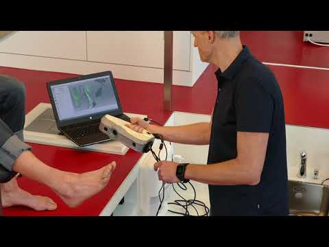
This is also confirmed by the practice of using - not our own, very modest, but people who worked with the scanner on expeditions. There are reviews on the manufacturer's website, we will only highlight two points in them. The first one is quite optimistic: for example, during two days of active use of the scanner, the battery charge was not fully used. The second confirms our conclusion about the desirability of the power off button: in between scans, we had to disconnect the cable from the battery, which gave a noticeable battery savings.
A little bit about overheating: the recall from the expedition mentions that even at an ambient temperature of +35 °C, the scanner could work continuously for 400 seconds. True, it is not specified whether only geometry or geometry + texture was filmed.
We tried it: at a room temperature of +24 °C, the scanner worked without turning off for 10 minutes in geometry and texture capture mode at a frame rate displayed in the Capture panel of 10–12 fps. Overheating did not occur, the process was stopped by us. True, no scans were made before that for at least half an hour, i.e. the scanner was at room temperature. The handle turned out to be the hottest part - it became noticeably warm, and after the process was stopped, the fan switched to minimum speed in less than half a minute.
After a five-minute break, the scanner worked for another 3.5 minutes in the same mode, after which it stopped due to overheating. It took him only 2-3 minutes to return to working condition.
Thus, the scanner is quite capable of working much longer than the recommended three minutes, but the rule is confirmed: the longer the scan cycle, the longer the subsequent pause should be.
Starting to scan
The work was carried out by us on a computer in the following configuration: processor i5-4570S (2.9GHz), RAM 16 GB, video card NVidia GeForce GTX 970 (4 GB), SSD was used as a drive. In the future, we will give the time for performing operations at different settings, so that the reader, comparing the parameters of his computer with ours, can roughly imagine his own time spent processing data.
We spent a lot of time choosing samples for scanning: it turns out that this is not such a trivial question for beginners “3D scanning operators”.
It has already been said that without special processing it will not be possible to work with objects that are transparent or have glare areas. Let's add a little more to this:
- since visible spectrum radiation is used to fix the geometry, black areas of the object may turn out to be unscanned: it is known that it reflects light poorly, and holes may appear in place of such areas;
- it is very difficult to work with objects that have holes, deep niches or depressions, especially if they are uneven in shape: we did not do well with the decoration for the aquarium in the form of the castle ruins above the grotto;
- when scanning a human face, problems sometimes arise in the most unexpected places: for example, some parts of the hairline may not be transmitted - hairstyles, beards, and for their correct transmission you have to tinker with the settings; the bright backlight from the standard camera means simply makes you close your eyes, turning off the texture flash makes things a little easier, but the structured backlight projector is so bright that even out of the corner of your eye it is difficult to look at it, and the colors will be fixed much worse, so you have to scan faces quickly and ask the person to look above the camera;
- objects whose shape is close to flat (for example, LCD monitors, even if they are not black and not with a glossy screen), cannot be scanned without taking special measures: in order to combine frames, the program algorithms must work with areas that have a noticeable mutual intersection, and when passing through the side edge of the monitor, the size of such an intersection will be too small, and you will have to use some external marks that are not related to the object itself, but provide opportunities for subsequent alignment;
- working distance is not just numbers: what is outside the near and far boundaries is simply not perceived and displayed in the 3D view field, so you have to make sure that some parts of the object do not go beyond these when moving borders; Of course, this does not mean that you cannot scan very large objects, just that you need to learn how to correctly move the scanner along them.
Therefore, we did not immediately rush to storm the heights of professionalism, examples of which are enough on the manufacturer's website, but settled on an object relatively small, but not tiny, and quite simple in shape - a wooden box with protruding crossbars, the volume of which was approximately 2 liters .
At first we got tired with the movement of the scanner relative to the object: the wires get in the way and sometimes get confused, I moved my hand with the scanner a little faster - the bell rang and a warning about the trajectory tracking failure appeared.
Of course, all this is a matter of experience, but in order to avoid unnecessary difficulties, we simply installed the scanner on a photo tripod, using the threaded hole in the base for fastening, and the object was placed on the rotating stand we had and, slowly rotating it, scanned. Things immediately went smoothly.
I must say that the skill of scanning without a tripod is developed quite quickly, you just need to take some time to practice.
So, we received a number of scans, waited for their registration when exiting the shooting mode and proceeded to further processing.
In passing, we note that in the "Shooting" panel, already familiar to us from the previous review, where the Kinect sensor was used, when Eva was connected, there were changes related to the features of this scanner. We have already said about this above, but now we will clarify.
Left - for Eva, right - for Kinect
There are already three positioning methods - it became possible to track only geometry, without texture. The range of scanning speeds has changed: the limit value has decreased to 15 frames per second instead of 30. The far border of the working area has changed - a meter instead of one and a half. There were texture brightness adjustments (understandable without explanation) and sensitivity (an increase towards "Extreme" means recording more information, which will better transmit poorly perceived surfaces, including black and shiny ones, but can lead to noise - flaws in the scan) .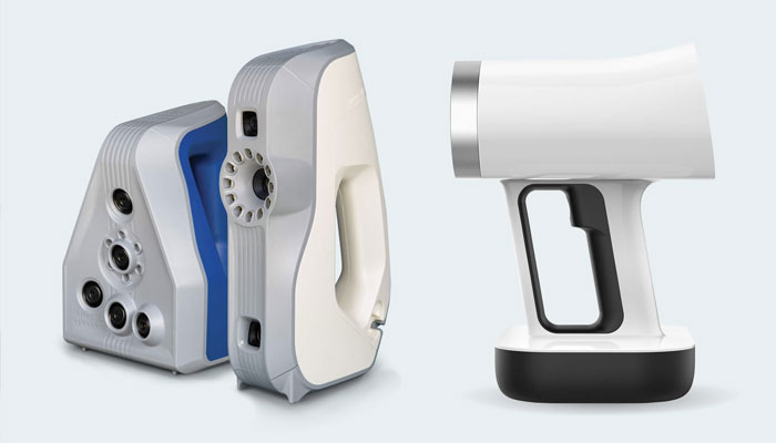 Finally, it becomes possible to turn off the texture flash: this mode, in particular, will allow you to observe a grid of structured illumination if, for example, you point the scanner at a sheet of white paper.
Turning off the flash does not cancel the capture of the texture at all, it simply starts using the available lighting. In order to be able to somehow take into account the level of illumination in this mode, an exposure time control appears.
If you turn off texture capturing by checking the corresponding line of settings, the only positioning method will remain - "Geometry".
By the way: the set recording delay works only when controlled from the "Shooting" panel, and when you press the corresponding button on the scanner, recording starts immediately.
The final step is to review the results obtained for the absence of unscanned areas or areas where increased noise is observed, that is, a large number of flaws (the minimum noise will be in the center of the scanner's field of view, so the object must be positioned accordingly).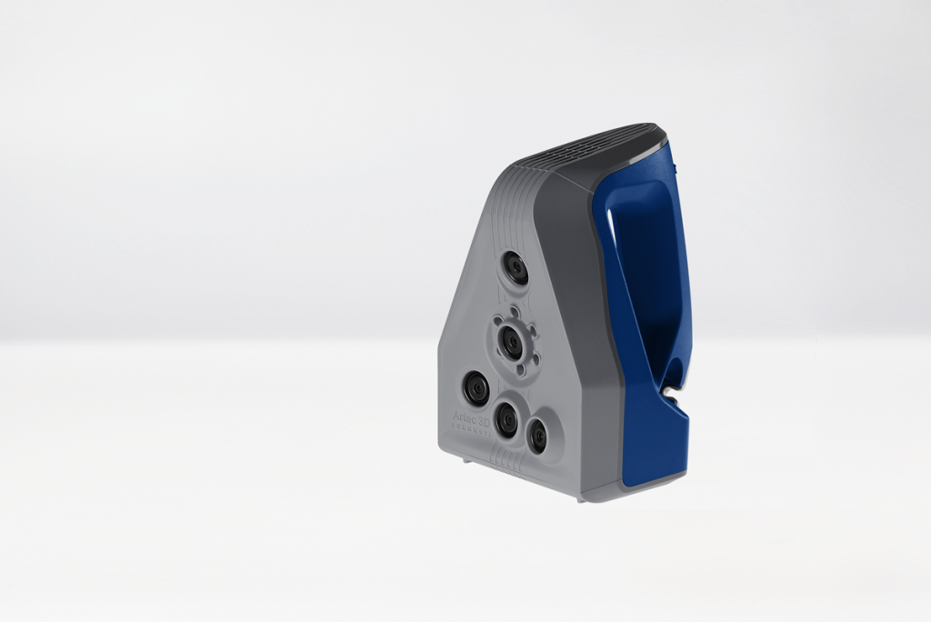 If this is found, additional scans will have to be done.
Information in the workspace will help to detect problematic scans: the "Quality" column shows the registration error score, the lower the value, the better. If the scan contains something very "outstanding", the numerical rating may be replaced by the word "Attention".
Another evaluation option is using the “Color” parameter in the “View” menu: one of its possible values is just called “Quality”, with it the color of the surfaces is selected depending on the quality of registration, red will signal an error.
It is only necessary to take into account that a somewhat simplified image is displayed in the 3D view window, and all data can be seen only in edit mode. So don't be surprised if, when you open edit mode, you see a lot of "new and interesting".
Processing the results
Naturally, the result must be protected from accidents by saving it as a project. We did not really limit ourselves when scanning, so for the box we got 3 scans with a total volume of 1.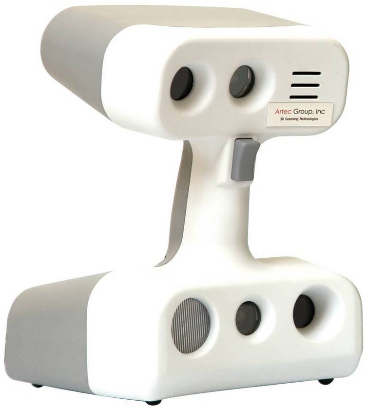 7 gigabytes, in which almost 2.4 thousand surfaces were recorded. But, of course, this is not in vain: just saving such an array of data, along with the history of commands, even when used as an SSD drive, takes a lot of time, and you won’t be able to move on to some other actions before the end of writing to the disk.
About the history of commands: if the scans have been processed, then the stage of saving the history is the longest, since not only the list of operations performed is saved, but also the previous data states for rollback, which can be useful. The length of the history (in the number of commands) and the maximum size (in megabytes), as well as the level of data compression during saving, can be set in "Settings - Resources":
You can see what was done in the workspace menu by clicking on the triangle next to the button rollback (Undo). True, there is not enough information displayed: the name of the operation is reflected, but on which object it was carried out (in this case, over which scan), it remains unclear.
Registration
Raw scans can be a heartbreaking sight - a set of surfaces randomly overlapping each other: Commands panel. After that, the scan looks much more fun:
Sometimes neither coarse nor fine successive registrations give the desired result: misaligned surfaces still remain. Then you can “shuffle” the frames in this scan a little - for example, put a number of frames into a separate scan and work with it. There is another option which we will mention below.
You can also cancel both registrations, and at any time, and not just with the Undo button: you need to right-click in the line with the name of the scan ("Workspace") and select "Reset position" in the menu that appears. In this case, the results of both coarse and fine consecutive registrations will be canceled immediately.
If desired, you can use the editing tools to remove "extra parts" - foreign objects that have fallen into the field of view of the scanner, including the stand and the operator's hands. The toolkit available in Artec Studio makes this operation quite convenient. But sometimes the superfluous is apparent: external elements can help the alignment, as, for example, it was said above about scanning thin objects.
We didn't spend a lot of time on selecting the best scans and frames, on all sorts of edits, and so on: we want to find out what the program itself is capable of if it slips low-quality initial data, and even in large quantities.
Assembling
When the scans are prepared, we proceed to assemble them to combine them into a single model.
To do this, select the scans participating in the assembly in the workspace with eye symbols and go to the Assemble panel, where these scans will be presented as a list. One of them, the first one in the list by default, is considered registered (combined), and the others will be combined relative to it.
It is marked with a blue circle, indicating the set of registered (superimposed) scans, which so far consists of one scan.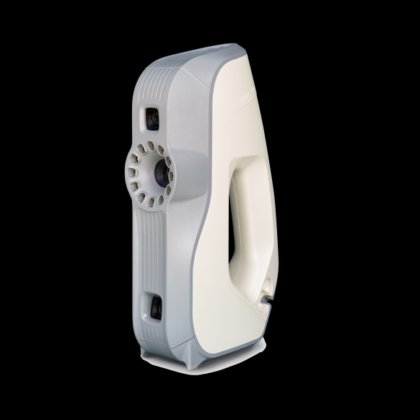 Of course, another scan can be assigned as such a base one.
Then select the scan or scans in the list that will be combined with the base one; they are marked with a green circle denoting an unregistered set. Accordingly, the scans themselves can also be displayed in the same color, you just need to select any option in the “Color” setting, except for “Texture”, but in the case of our box, it was the texture that was needed for the correct orientation. The numeric button "1" of the keyboard will help to display only the registered set, only the unregistered set - "2", both sets - "3".
We combined scans in pairs.
First, holding down the Shift key, move the unregistered scans relative to the registered one with familiar mouse movements. If at the same time it is possible to combine them normally, then you can simply click the "Apply" button, but more often you have to use alignment by points for a pair of scans. To do this, you need to orient the second scan relative to the first one so that they “look” approximately in the same direction, and then set pairs of identical points on their surfaces.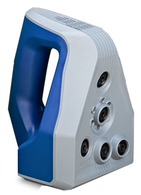 It is not necessary to strive for very high accuracy when choosing points in each pair, it is enough to specify them approximately.
Points pt[5] are located on the back side of the box, so their positions in this view do not match
Press "Collect by Points" - the scans are aligned, the set of registered scans is now doubled. Do the same with the rest of the scans and click "Apply".
These are not the only assembly options, there are many more of them in Artec Studio, but we will not dwell on others in detail - they are described in the instructions quite clearly. However, it should be noted that the "Combination with Constraints" assembly algorithm allows you to work not only with scans, but also with surfaces within a single scan; this is useful if exact sequential registration could not match them.
So, the scans are combined, you can proceed to the global registration - the transfer of all frames into a single coordinate system. It is launched from the "Commands" panel and has three set parameters, which are shown in the screenshot:
This procedure is very resource-intensive, even on a powerful computer it can take a long time: with the default settings (they are shown above), we have this procedure took more than seven minutes - 423 seconds! So you think, is redundancy in scanning so good ...
And you can't say that the result was perfect.
Here we have something that we did not finish at the stage of pre-processing the scans and during their assembly. You can go back, but there are other options for improvement: to conduct a global registration first for two or three scans that could not be combined perfectly, and then again for all. But these are very time-consuming procedures, besides, our task is to test different mechanisms offered in Artec Studio - for example, removing outliers, i.e. small surfaces that are not connected with the main ones and separated from them.
The procedure is also launched from the "Commands" panel and has two parameters, the default values of which are shown in the screenshot:
The first one is set to 2 if there are many outliers, and to 3 if there are fewer.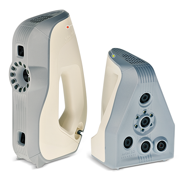 The second parameter means the step size of the triangulation mesh in millimeters, the range depends on the scanner type, but the main thing is that the value must be the same as that of the similar parameter in the subsequent fusion procedure.
This algorithm somewhat improved the appearance of our sample, but it took quite a long time: almost 4 minutes (224 s).
Gluing
From the resulting one, you can already “glue” the model. The function is called: "Glue", and there are three types: fast, smooth and accurate. The former is faster than the others, but produces poorer results requiring additional processing and is therefore mostly suitable for visual evaluation. The second type - smooth fusion - is the most time-consuming and resource-demanding, but it is good for noisy surfaces (that is, "littered", containing a lot of flaws), and is able to work even in the absence of part of the 3D data; best suited for creating models of the human body or head, because it can compensate for small, up to 3-5 mm, changes in the shape of an object.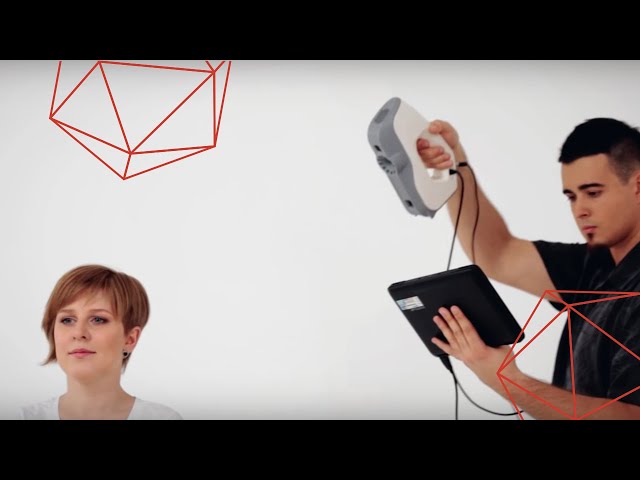 Precise fusion works faster than smooth fusion, it conveys fine details and thin edges well, since it uses more raw data, but for noisy surfaces in some cases it can increase noise, and it also does not compensate for shape changes.
Each type has a set of set parameters, for smooth and precise it is the same and together with the default values for the Eva scanner is shown in the screenshot:
models will have different values) and radius (default 2).
Let's see what fast gluing will give us and whether it is so fast. Here is the result with the default parameters:
Time spent 49.4 s — quite fast compared to the previous steps. However, the resulting model has obvious defects.
Now smooth merging, also default values:
For some reason it turned out even faster than with fast merging: 41.1 s. And the model differs from the one obtained in the previous case for the better.
Finally, precise gluing:
A very good result.:quality(80)/images.vogel.de/vogelonline/bdb/991500/991549/original.jpg) On closer examination from all sides, there are still some flaws, but in general, the difference with the previous versions is obvious. And the time of 41.0 s is practically the same as with smooth, but still less than with fast.
On closer examination from all sides, there are still some flaws, but in general, the difference with the previous versions is obvious. And the time of 41.0 s is practically the same as with smooth, but still less than with fast.
We have done gluing with other sets of scans of the box, and although the absolute values in seconds have changed, the time spent on accurate and smooth gluing again turned out to be less than on a fast one. Probably, the processing speed for different types of gluing depends on the specific model.
There is another option, very interesting: gluing, which is performed simultaneously with scanning. To switch to this mode, simply put a checkmark in the "Shooting" panel in the line "Merge in real time"; although this is not specified, it is obvious that we are talking about fast gluing. A big plus: you can immediately see in a more or less real form what is obtained as a result of scanning. But there are also disadvantages, the main of which is that you need a powerful computer.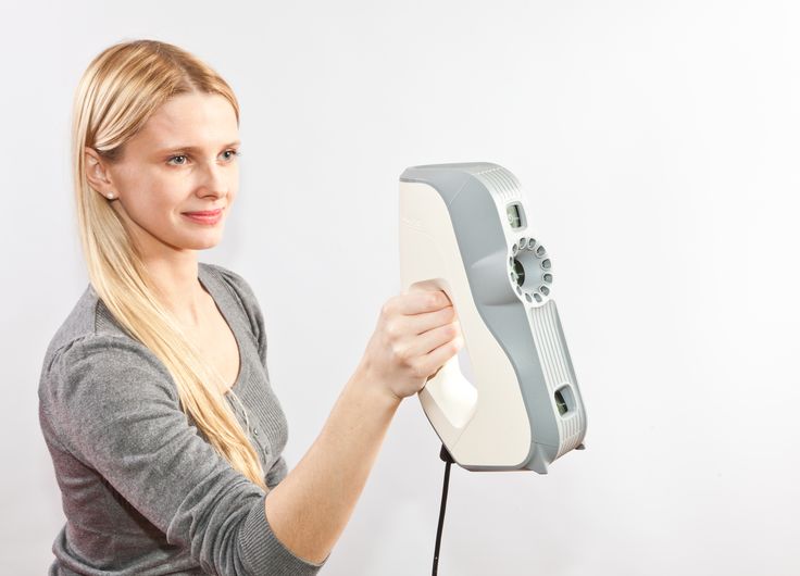 In addition, it is not at all a fact that in this case everything will stick together safely; however, nothing prevents you from doing the gluing again using one of the methods described above. A less significant, but also not always negligible minus: the image in the 3D view window does not display the texture, even if its capture is not turned off - the texture is fixed and recorded, but its simultaneous imposition is impossible.
Finishing
You can proceed to the final procedures - finishing. There are also quite a few tools here:
Unfortunately, the manual we downloaded is slightly behind the version of the program and lists slightly different tools (even in quantity: there are eight instead of six in the manual). But the effect of some of them is more or less clear from the name, and there are still explanations for two not very clear explanations: mesh optimization reduces the number of polygons in the model with a minimum loss of accuracy, and retriangulation makes the triangle mesh uniform. All of these tools except the last one have configurable parameters.
The small objects filter even with the default value removed all the garbage around the model - it was, but not much. But we needed to fill the holes to a greater extent: to test the operation of this algorithm, we left a significant part of the lower plane of the model unscanned.
With the default value (100) and close to it, the effect was not noticeable at all, only with an increase to 800 the hole was tightened.
True, it didn't work out perfectly.
Now smoothing: its purpose is described as "filtering noise of small amplitude", which can be regarded as the removal of small flaws. In reality, it makes the model a little swollen, and the noise really becomes less. But here the main thing is not to overdo it: for smoothing, you can set the number of steps, with a default value of "1" the effect is not so significant, and when you increase it to 25, the whole model looks like melted ice cream:0007
All described commands work quickly: even with a significant change in parameter values, processing takes only a few seconds, and more often even a fraction of a second.
It was possible to go another way - to use the "Edges" panel, which works not only with edges, but also with holes. The tool is very convenient: in each of the tabs - "Holes" and "Edges" - a list of detected defects is displayed, which is automatically generated immediately after starting this panel. Nothing was found on the model obtained after precise gluing, and we took advantage of the result of quick gluing, where there were a lot of defects, you could just get lost in them.
However, the developers of the program foresaw the following situation: each defect can be identified in two ways. You can hover the cursor over the desired place in the model image - the defect will be highlighted, and clicking will also select the line corresponding to it in the list of holes or edges, depending on the selected tab. If you select a line in the list, then the defect corresponding to it will be highlighted in color on the model image, and the image itself will turn in the right place to the observer (such rotations are not always convenient, but they can be canceled by unchecking the "bird" in the corresponding position of the panel).
Holes can then be filled in and edges smoothed - all found or individual, at the choice of the operator. And for the edges, you can set the intensity of smoothing. Here are examples of the action:
Filling a hole
Edge smoothing, on the left screenshot the selected edge is highlighted in red, and the estimated contour after processing is shown in yellow
Having eliminated the defects if possible, you can proceed to mesh optimization. The fact is that our model of a simple box, obtained by precise gluing, contains more than 300 thousand polygons and 150 thousand vertices, and therefore pulled 95 megabytes is quite a lot.
After mesh optimization (this procedure has 4 parameters and can be performed by polygons, by accuracy and by total polygon size; we used the default values), the model has changed a little: it has become smoother, some information about fine details has been lost, but has become much less complex, and its "weight" in megabytes has decreased by more than 15 times.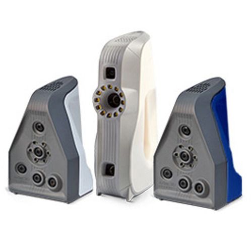
The process took 16.5 seconds.
Retriangulation can also lead to some simplification of the model. If we take the value of its only parameter "Resolution" equal to one (by default), then the procedure takes a relatively long time - 48.8 s, the appearance of the model practically does not change, the number of polygons, vertices and "weight" even increase.
In some cases, a slight reduction in the number of polygons and vertices is possible, and the "weight" can be halved. It is necessary to increase the value of the parameter carefully: the values listed in the screenshots decrease, but the model is greatly simplified and ceases to look like a sample. When the value is reduced to 0.5 (a dot is used as a separator), the execution time becomes much longer - in our case it has increased to 181.2 s, and the model becomes overly complex, the values of the mentioned characteristics increase greatly. With further reduction, the process may be interrupted due to lack of memory, we recall: our computer has 16 GB of RAM.
Texturing
If we are scanning an object with a texture to obtain a model whose surface color must fully match the sample, then the final step will be texturing - applying a texture from individual frames to the resulting model. This is perhaps the only stage in which the video card plays an important role - even in the "Texture" panel there is an estimate of the required video memory, which may need more than the computer's RAM.
First, select the desired model from the list, if there are several (we have the results of three types of fusion, we chose the exact one), as well as the scans from which it was obtained.
Then you need to specify which texturing method is preferred: building a triangle map or a texture atlas. We will not go into theoretical details, we will only mention a practical point: the triangle map is built faster, but is more suitable for quickly viewing the resulting texture. Atlas - for the final export, it is important to properly simplify the mesh before texturing.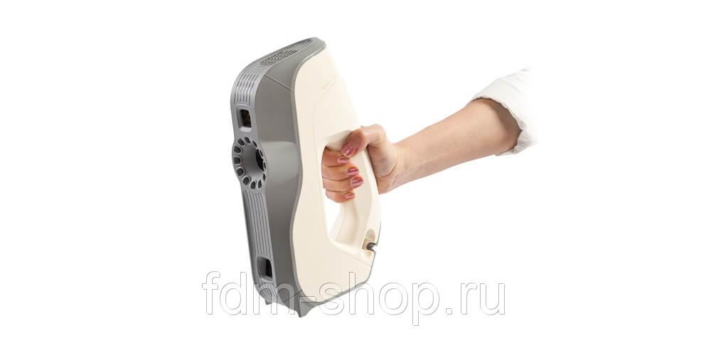
Next, set the parameters. For a triangle map, you can set the dimensions of the triangle in pixels (default 10), but increasing the size will require more memory, RAM and video.
For both methods, the size of the resulting texture is also set:
This also affects the memory requirement.
With the default values shown in the first screenshot of the Texture panel, the process of building the triangle map took 49 seconds, while the texture atlas took almost four times longer, 178 seconds. To be honest, it is very difficult to spot the differences immediately and with the naked eye.
Texture building: texture atlas on the left, triangle map on the right
Increasing the size of the triangles from 10 to 30 with the same texture size increases the texture time from 49 to 52 seconds. We tried to change the texture size from 4096x4096 to 16384x16384 with 20 triangles, but the procedure didn't work out: there were not enough four gigabytes of memory available on our video card!
The program ended abnormally after this message.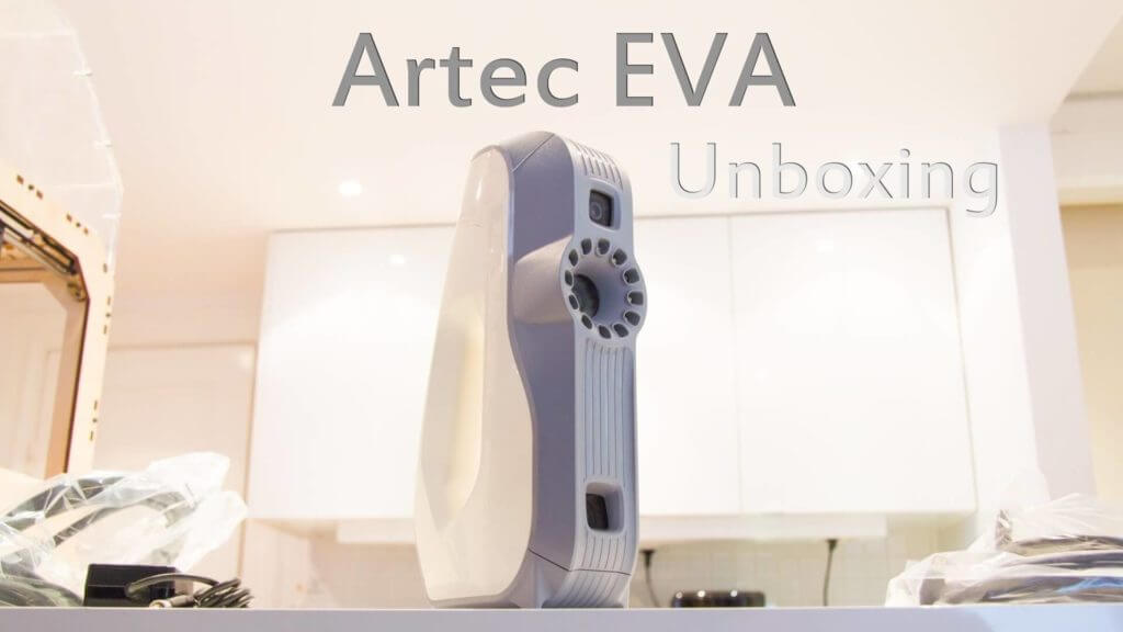 For 10 triangles with a texture size of up to 8192x8192, the process takes 51 seconds.
At the same texture size, the creation of the textured atlas took 186 seconds, which is also slightly more than for 4096×4096. And even for 16384 × 16384, the atlas was created, and it did not take much longer - 224 seconds. To recalculate an already obtained texture in less time, the instruction recommends using the "Retexture using current UV coordinates" function, but it is available only for textures applied using the "atlas" method.
Next, it's possible to slightly adjust the texture by adjusting the brightness, contrast, saturation, hue and gamma correction. True, working with a large texture (more precisely, with the resulting large data) is quite difficult - any change is worked out for a long time, so we decided to stop at texture atlas 8192×8192.
The amount of data increased many times over - up to 205 megabytes. Therefore, there is no need to get carried away with large textures, for the vast majority of cases, 4096 × 4096 textures will be enough, while the amount of data for our model is noticeably smaller: 61 megabytes. And try to find the difference:
Left texture 8192×8192, right 4096×4096
If there is something extra on the resulting model, for example, part of the stand, you can use the editing tools again.
Saving and exporting
Everything, now it remains only to save the project again with all the data received at different stages. If some scans were deleted during the work, then when saving, a request will appear:
It is better, of course, not to delete anything permanently, but sometimes this has to be done in order to save space on the media - the volume occupied by the project can already be calculated in gigabytes .
If necessary, you can export the model to one of the available formats, such as STL. The color texture is not supported by this format, and only information about the geometry of the model will be saved in the STL file.
If we select a texture-enabled format, such as OBJ, then the color information will be saved as separate files, the format of which can also be selected from JPG, BMP, and PNG.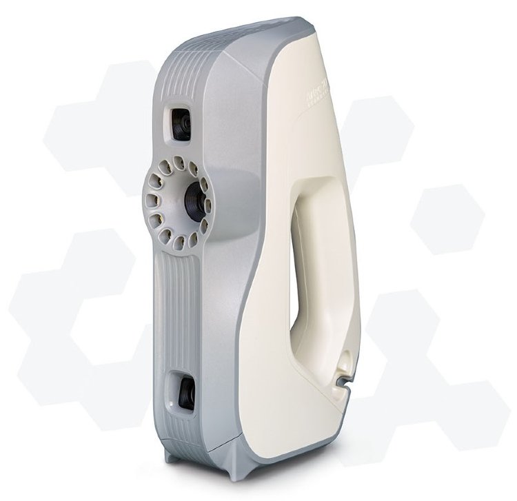
Summary
As with anything, 3D scanning requires experience and skill. At first, it is quite difficult to move the scanner so that the object remains in the working area all the time, and besides, do it smoothly and not too quickly. With a stationary scanner and an object rotating on a stand, we also did not immediately succeed in this regard, especially when the sample is not as simple as a box. Only with experience comes the ability to orient the scanner so that the object is in the center of its field of view. And, of course, only with time you can learn how to properly scan specific objects - dark surfaces, lush curly hair, restless children or animals.
Employees of the company assured us that all this was being done, and without much trouble; There is no reason not to believe them: there are many examples of excellent models made by Artec scanners on the company's website and even more on the Internet - they are posted by the owners of the scanners. But still, it must be said: it would be naive to expect that the owner of the scanner will get everything at once.
You learn much faster how to work in Artec Studio. But here sometimes the problem of choosing between necessary and sufficient arises, and not only in the above case with the texture size, but also with the amount of data obtained at the scanning stage. Yes, the algorithms of the program will help to get a completely high-quality model even if there is no information about some parts of the object, but even here everything will depend on the experience of the operator: for example, even the best program will not be able to attach an unscanned ear or nose. Therefore, at the initial stages of mastering the scanning technique, it is still better to get an excess of information, especially in cases where the object came to you for a while and you cannot rescan it later. But you need to use the received data selectively, not using all the received scans at once, especially when Artec Studio is running on a computer that is not the most powerful, otherwise the processing time at each stage may turn out to be excessively long.
Despite the lack of special experience with 3D scanners, we still allow ourselves to express a couple of wishes to the company's developers.
First and foremost, USB 2.0 ports are coming to an end, as modern computers, laptops and motherboards have fewer USB 2.0 ports, it will become increasingly difficult to comply with the requirement not to connect scanners to USB 3.0. But USB 3.1 ports have already appeared and every day more and more actively will be introduced! Therefore, it is highly desirable to quickly resolve the issue, if not with the full use of USB 3.0 capabilities, then at least with the compatibility of scanners with such ports.
Less important, but much easier to implement, will be our second wish: it is quite logical and customary when a device with its own power source also has a power switch. It's not even about saving electricity, although in the West, unlike in Russia, developers are proud of every saved watt-hour. It’s just that the scanner’s operation, albeit in standby mode, in between scans (which can be tens of minutes or even hours) can hardly be considered a necessity, and turning off its power by unplugging the cable from the outlet is not the most convenient solution.