Architectural models 3d printing
Guide to 3D Printing Architectural Models
Despite a move from the drawing board to digital screens, physical architectural models still play a significant role in helping architects visualize blueprints.
3D printing technologies help bridge the gap between digital and physical worlds and empower architects and model makers to create high-precision architectural models quickly and cost-effectively directly from digital drawings.
This guide provides comprehensive information about using 3D printing to produce architectural models, the different 3D printing processes for architecture, and the workflow for creating 3D printed models from architectural computer-aided design (CAD) software.
White Paper
This white paper covers how to make smart modeling decisions, from choosing scale to designing for assembly to post-processing, and how to use these strategies in common software ecosystems.
Download the White Paper
Since the age of the Pharaohs, architectural models have served as physical representations during structures’ development to help sell a project, support fundraising efforts, and solve construction challenges.
Traditionally, model-making is a manual craft that involves working with materials such as wood, ceramic, cardboard, or clay, which can be extremely time-consuming and repetitive. Architecture studios and practices today have access to a wider range of tools, including CNC milling machines, laser cutters, and 3D printers that can reduce labor needs and speed up the workflow.
Modern 3D printing processes provide architects and model makers with the means to revolutionize how models are made. They do this by:
-
Speeding up the architectural model making process.
-
Translating CAD drawing directly into physical 3D models with a high level of precision.
-
Developing intricately designed parts that’d be hard or impossible to produce by hand.
-
Simplify communication and showcase specific areas that would be hard to convey through conventional 2D drawings.
-
Creating more design iterations at reduced production costs.
For example, model makers Renzo Piano Building Workshop (RPBW), founded by the Pritzker Prize laureate architect, use an SLA 3D printer to quickly develop and fabricate accurate models.
“Our models change every day or even every hour. Because the architects change the project very quickly, most of the time, we don't have enough time to do it by hand. Therefore, we have to find a way to do it quicker,” said Francesco Terranova, model maker at RPBW.
3D printers can create models within a few hours and even operate overnight to save time. “The good thing is that we can launch the printer in the night, and when we come back in the morning, we find the model done. This way, we don't lose time during the day,” said Mr. Terranova.
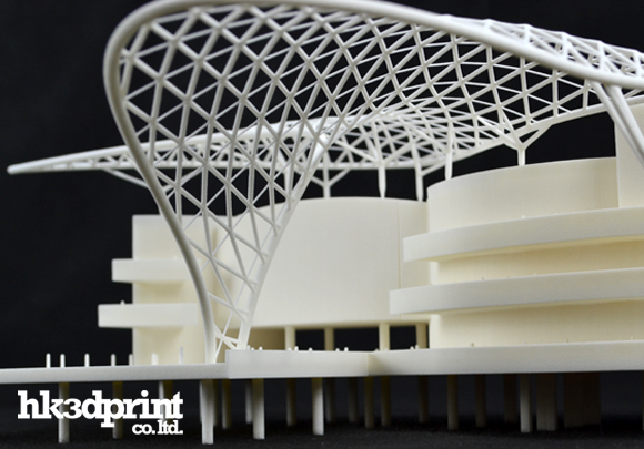
3D printing in architecture is ideal for intricate parts—the trees on this model were 3D printed on a Formlabs SLA 3D printer.
3D printing can be used to produce architectural models of entire buildings, but also in combination with other tools and processes.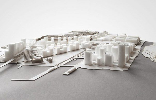 RPBW’s model builders may use CNC machining or laser cutting to produce the base parts of their architectural models and a 3D printer to develop more complex or intricate components like stairs, trees, spheres, and curved surfaces, which would be time-consuming to manufacture by hand. For example, the RPBW team 3D printed the complex joints of the columns for the model of the new San-Giorgio motorway bridge in Genoa that has recently replaced the Morandi bridge that collapsed in 2018. This combination of 3D printing alongside traditional manufacturing solutions speeds up the creative process and increases the accuracy levels of architectural models.
One of the main goals of 3D architecture models is to simplify communication between architects and to make it easier to showcase plans to clients. Los Angeles-based design firm Laney LA’s projects are mostly custom homes, so communicating the scale of a home or structure is particularly important. Architect Paul Choi and his team use 3D printing to showcase specific areas of the project that can be more complicated to convey through conventional 2D drawings.
Laney LA’s architects use 3D printing to create models that allow them to view the project from a fresh perspective while simultaneously providing vantage points.
“It's fun to always try to depict a certain idea about the project and isolate that through the model, whether it's a certain room or a space that we want to highlight through a section cut of the model, or even the topography of the site,” Choi said.
RPBW’s model makers use a Form 3 SLA printer to speed up the production of scale models.
When it comes to 3D printing architectural models, not all methods are created equal. It is important to choose the right printing technology for specific use cases.
The most popular 3D printing technologies for architectural models include stereolithography (SLA), fused deposition modeling (FDM), selective laser sintering (SLS), and binder jetting.
Stereolithography was the world’s first 3D printing technology, invented in the 1980s, and is still one of the most popular technologies for professionals.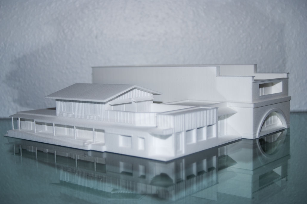 SLA resin 3D printers use a laser to cure liquid resin into hardened plastic in a process called photopolymerization.
SLA parts have the highest resolution and accuracy of all plastic 3D printing technologies. SLA parts also offer the smoothest surface finish that is easy to paint.
SLA parts have sharp edges, a smooth surface finish, and minimal visible layer lines that are ideal for highly detailed presentation models. This model was printed on a Form 3 SLA printer.
SLA is a great option for highly detailed presentation models for presenting concepts and ideas to clients or the public.
Thanks to fast-printing materials like Draft Resin, SLA is also the fastest 3D printing process for most parts. While desktop SLA printers offer a more compact build capacity, with large-format SLA 3D printers like the Form 3L, architects and model makers can create truly large-scale models.
Sample part
See and feel Formlabs quality firsthand.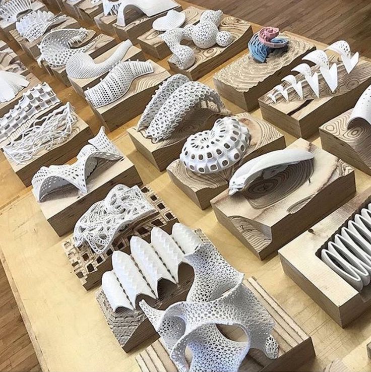 We’ll ship a free sample part to your office.
Request a Free Sample Part
Fused deposition modeling (FDM), also known as fused filament fabrication (FFF), is the most widely used form of 3D printing at the consumer level, fueled by the emergence of hobbyist 3D printers. FDM 3D printers build parts by melting and extruding thermoplastic filament, which a printer nozzle deposits layer by layer in the build area.
FDM has the lowest resolution and accuracy from the four 3D printing processes and is not the best option for printing complex designs or parts with intricate features. It is ideal for basic concept design models produced during the initial stages of design as it can create relatively large models fast and at a low cost.
FDM printers struggle with complex designs or parts with intricate features (left), compared to SLA printers (right).
Selective laser sintering is the most common additive manufacturing technology for industrial applications.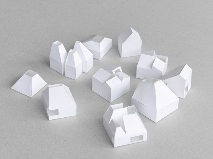 SLS 3D printers use a high-powered laser to fuse small particles of polymer powder. The unfused powder supports the part during printing and eliminates the need for dedicated support structures.
SLS printing is ideal for complex geometries, including interior features, undercuts, thin walls, and negative features. Parts produced with SLS printers have excellent mechanical characteristics that make them suitable also for structural parts.
SLS is ideal for complex geometries and intricate details. The details on this model were printed on a Fuse 1 SLS printer.
Binder jetting 3D printing technology is similar to SLS printing but uses a colored binding agent to bond powdered sandstone material instead of heat. Binder jetting printers can produce vivid, full-color 3D architecture models.
Parts produced with binder jetting have a porous surface and are very brittle, which means that this process is recommended only for static applications.
Binder jetting printers can produce vivid, full-color architecture models.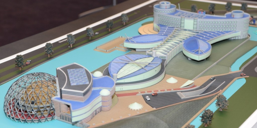
| Stereolithography (SLA) | Fused Deposition Modeling (FDM) | Selective Laser Sintering (SLS) | Binder Jetting | |
|---|---|---|---|---|
| Resolution | ★★★★★ | ★★☆☆☆ | ★★★★☆ | ★★★☆☆ |
| Accuracy | ★★★★★ | ★★★★☆ | ★★★★★ | ★★★☆☆ |
| Surface finish | ★★★★★ | ★★☆☆☆ | ★★★★☆ | ★★★☆☆ |
| Ease of use | ★★★★★ | ★★★★★ | ★★★★☆ | ★★★★☆ |
| Complex designs | ★★★★☆ | ★★★☆☆ | ★★★★★ | ★★★☆☆ |
| Build volume | Up to 300 x 335 x 200 mm (desktop and benchtop 3D printers) | Up to 300 x 300 x 600 mm (desktop and benchtop 3D printers) | Up to 165 x 165 x 300 mm (benchtop industrial 3D printers) | Up to 254 x 381 x 203 mm (industrial 3D printers) |
| Price range | Professional desktop printers start at $3,500, large-format benchtop printers are available from $11,000.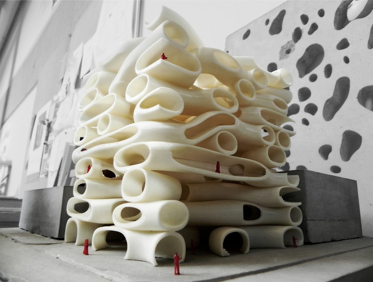 | Budget printers and 3D printer kits start at a few hundred dollars. Higher quality mid-range desktop printers start around $2,000, and industrial systems are available from $15,000. | Benchtop industrial systems start at $18,500, and traditional industrial printers are available from $100,000. | Binder jetting 3D printers are expensive industrial machines, with prices ranging from $30,000 to $100,000+. |
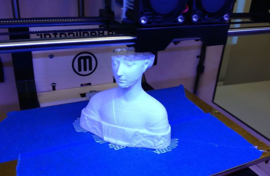
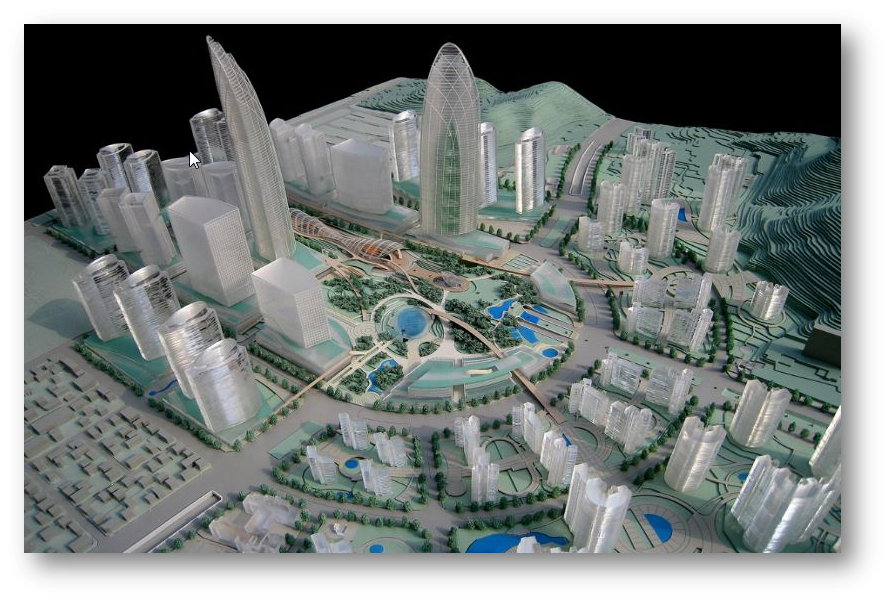
A team from the Institute of Architecture at the Hochschule Mainz - University of Applied Sciences reconstructed the medieval german cities of Worms, Speyer, and Mainz with large-scale 3D printed models.
Most architects today already work in the digital space, using architectural CAD software like BIM (Revit and ArchiCAD), Rhino 3D, or SketchUp to create digital CAD designs. However, these digital files cannot always be used to create the physical scale models directly with 3D printing.
A successful transition from a CAD model to a 3D printable file relies on a baseline understanding of design for 3D printing, how regular modelmaking constraints relate to preparing a file for 3D printing, and how to approach and make smart modeling decisions, from choosing the right scale to designing for assembly to post-processing.
Architectural models are conventionally assembled with a variety of materials and components. 3D printers help fuse these components into as few individual parts as possible, but some assembly is still required for two reasons:
-
The constraints of the build volume: Unless you’re using a large-format 3D printer such as the Form 3L, you might need to divide the model into multiple parts to fit it inside the build volume of the 3D printer.
-
The need to show interior detail or materiality: Certain models require components that come apart to reveal more information about the design.
The size and geometry of different components within an architectural model are key considerations when preparing an architectural model for 3D printing. Generally, large models, models with multiple components, and models with intricate features are split into 3D printable components for assembly. Parts can then be easily joined together through chemical adhesion or mechanical assembly; the high accuracy of the prints with technologies like SLA and SLS ensures that the parts join together seamlessly.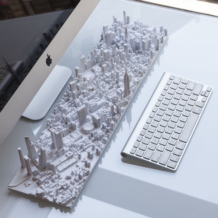
Getting the best results requires applying modeling strategies for assembly, including:
Since each housing unit followed the same design, it made sense to simply print one removable unit that would allow the client to understand the generic unit typology. Model by Stanley Saitowitz | Natoma Architects Inc.
Advancements in CAD technology have drastically simplified the process of developing 3D printable files. Modern CAD platforms have dedicated 3D printing modules to help architects convert a CAD design into a printable model. However, do remember that you are still working at a 1:1 scale–some quick conversions will be required to achieve the correct dimensions at the print scale.
Developing architectural models require some important considerations depending on the CAD platform used. These CAD-specific considerations include:
-
BIM Workflow: Developing 3D printable models with BIM software that leverages parametric modeling such as Autodesk Revit or Graphisoft ArchiCAD requires some component management.
 Components such as ductworks, double glazed windows, and HVAC systems do not translate in 3D prints and must be removed, while other parts such as doors, windows, walls, slabs need to be thickened.
 -
Surface Modeling Workflow: This workflow is often an easier approach, starting from 2D drawings solely with the intention to 3D print. It involves exporting a simplified drawing, scaling it down, and extruding and trimming until there’s an external shell.
Download our white paper for step-by-step workflows in common architectural CAD software ecosystems.
The next step in 3D printing architectural models is transcribing your digital 3D model into a language your 3D printer understands. Accomplishing this requires the use of slicing or print preparation software, such as PreForm. Whether you’re new or experienced, slicing software is generally intuitive to use. The software highlights details such as walls that may require strengthening, unsupported areas, and closed volumes that affect the structure of the 3D print, which can be addressed before printing.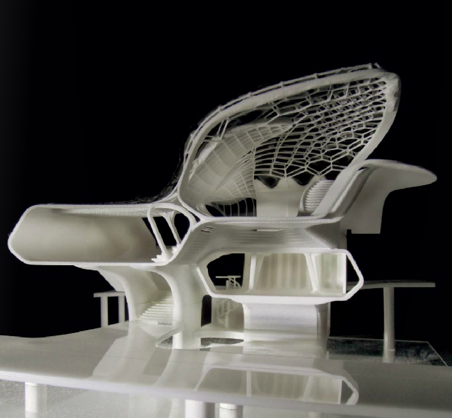 Using the software, you can also optimize settings such as resolution, build platform position, and support structures.
Materials play an important role in conveying the underlying concept of a design. It isn’t always imperative to simulate the exact color and texture of a material, but it can help to distinguish between different materials. Splitting a model by its components makes it possible to display materiality, as parts can be produced with various 3D printing materials, or individually painted with different colors.
This site model was created with laser-cut chipboard. The primary building was 3D printed with both Clear Resin and White Resin. Model by Schwarz Silver Architects.
Post-processing differs depending on your specific 3D printing technology, but generally includes sanding, bonding, and painting models.
Here’s an overview by 3D printing process:
| Post Processing Technique | Stereolithography (SLA) | Fused Deposition Modeling (FDM) | Selective Laser Sintering (SLS) | Binder Jetting |
|---|---|---|---|---|
| Sanding | Light sanding is recommended to remove support marks. | The lower quality of FDM prints means sanding is required to get a smooth finish. | No sanding is required due to the quality of the finished parts. | No sanding is required. |
| Bonding | Bonding of SLA components is done with super glue or liquid resins. | FDM components can be assembled using adhesives such as super glue. | SLA components can be assembled using adhesives such as super glue. | Components printed using binder jetting printers can be bonded using super glue. |
| Priming and painting | SLA components can be painted to achieve the desired finish. | FDM components can be painted to achieve the desired finish. | SLS components can be painted to achieve the desired finish. | No painting is required for full-color parts. |
Professional SLA and SLS 3D printers empower architects with the tools to create accurate and attractive 3D architectural models.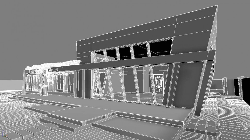 Choose the Form 3 for a compact solution that can fit on a desktop, the Form 3L for high resolution large-format models, and the Fuse 1 for structural parts and the most complex shapes.
See the Form 3See the Form 3LSee the Fuse 1
Download our white paper for an in-depth overview of modeling strategies, step-by-step workflows in common architectural CAD software ecosystems, as well as printing and post-processing recommendations.
Download the White Paper Now
Printing Architectural 3D Models | Life of an Architect
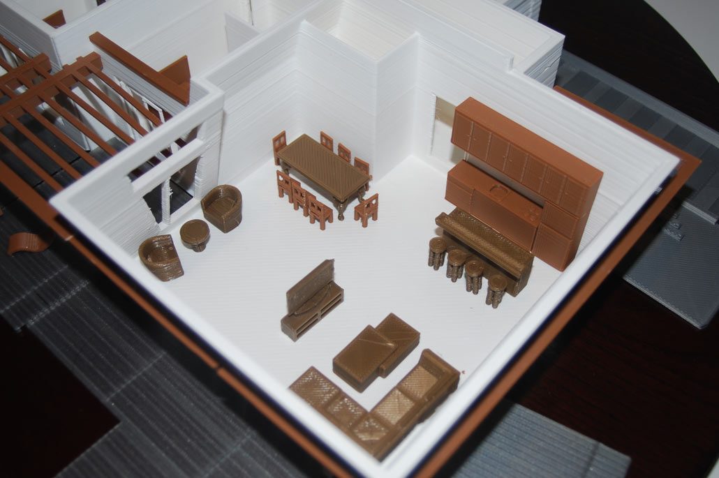
Architects have been using 3D printers for years so the process of printing architectural 3D models isn’t new, but over the last two weeks, we have been experimenting with the process of creating a model for one of our residential projects. I am definitely late to the party on this one but my last office didn’t see any value in this sort of design exercise – we built a lot of models by hand using more traditional materials. So I have been simply looking at the 3D printer that has been sitting in my office for the last two years and I finally decided to put it to work.
The image above represents the current fruit of our exploratory labors, and I have to say that while I’m not completely satisfied, it does look pretty good and the attention generated in the office regarding this particular project has been very interesting to watch develop.
But I’m getting in front of myself, let’s back up just a bit.
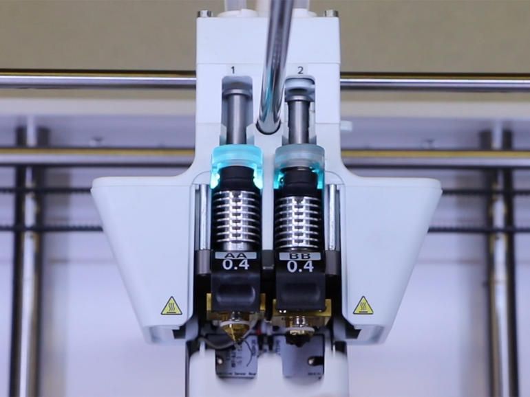
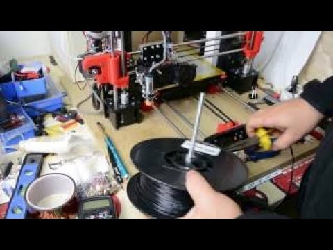
This is the 3D printer we have – a Ultimaker 3 Extended …which is no longer made and has since been replaced with the newer and improved Ultimaker S5 3D Printer but let me prepare you that these are definitely NOT cheap pieces of equipment. I don’t know how much the one we have in the office cost when it was purchased but the new ones will run you around $6,300 (ouch!). I will point out that this post is not intended to be a review of 3D printer equipment, since I am only 2 weeks into this experience I am not prepared to deep dive into the specific parameters of why one printer would be better than another with the exception to two things:
- The size of the “build area” of the printer.
 The one I used has a 7″ x 7″ footprint which presented challenges to how delicate everything was once we shrank the house footprint down so that it would be small enough to fit within that area
 - Speed at which the printer prints. Speeds kills, and in this case, slow speed kills the quickest.
This piece of equipment is not very large relatively speaking and while it does make some noise and put out some heat, the people who sit immediately adjacent to the equipment had a pretty good attitude about it (they only “joked” that they wanted to kill me despite the fact I was printing for DAYS!!) You can see the giant roll of printing filament on the back of the enclosure. These rolls are pretty large and we were able to print continuously without worrying that we would run out mid print.
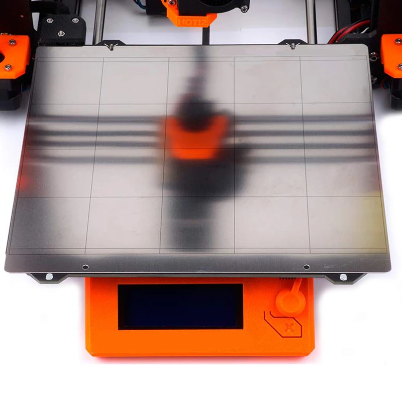
The image above was the roof from one of our initial prints … and it turned out terrible. It was printing out too thin and as a result, the heat from the printing bed, as well as from the printer head, was causing our model to deform and warp. We ended up solving this problem by slightly increasing the thickness of the planes we were printing, but we also changed the orientation of the print. Rather than printing it out horizontally – just like you see in the image – but we ended up rotating it on edge so that it printed vertically. Visually the end product looked vastly superior but the printing time changed from about 4 hours to 14 hours.
Here is what one of the first test prints looked like – looked okay but we had problems again with the thickness of our walls and our window frames. You can even see on the bottom left where we printed out the entry overhang and you can actually see through it! (You can click here “The Front Door Experience” to see what that overhang was supposed to look like). We also had issues with the window frames breaking when we broke away the temporary construction material the printing process creates when forming the model.
In general, this model was not very good, but we could easily see what we needed to fix and the next model would be a lot better.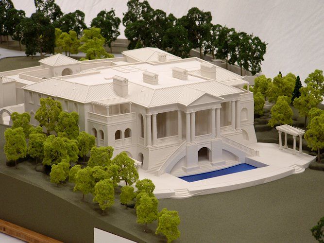
The other challenge we faced, which I mentioned earlier, was the limitations of the printing bed area. We had to keep everything to a 7″ x 7″ max footprint which meant the base we wanted to create to set the house would need to be made into 4 pieces and then joined together after that fact.
Easy enough, right?
Easy if you like waiting 35 hours to basically print out 4 sections of the base that are only 1/2″ thick … which I don’t.
Here is what the base looked like after an amazingly long time printing. The thing that was a little disappointing was coming to terms with the amount of extra work that would be prepared if we really wanted these sections to look clean … which I typically want. You can see all the striations in base sections and someone would have to take some additional time and care to sand all of these pieces to make them smooth.
Who has time for that?
To combat some of the printing irregularities, and to highlight the exterior and the interiors, we decided to paint the exterior black while leaving the interiors white – a little trick I picked up from my friend Anthony Laney at Laney LA – the person who showed me the first 3D printed model that actually made me think “WOW – that looks amazing”.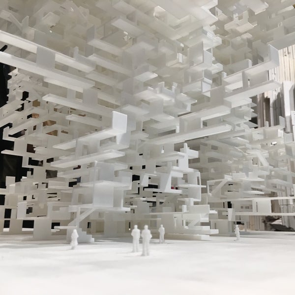
The process of making the exterior black, while keeping the interior white was pretty simple … but took more time and some additional effort. We ended up just masking everything off using tape and an X-acto knife to keep everything nice and tidy.
When you look pretty close, you can see all sorts of irregularities in the printing process, but you have to be looking for them. Keep in mind that this model is only 7″ square at its furthest dimension points.
At this scale, and with a coating of black spray paint, most of the things that would drive you crazy tend to disappear.
Mostly.
This model is shockingly small and because I am writing this post while on holiday from Mexico, I can’t just pop back into the office to take a picture that would help convey its size relative to something else. Due to its size, you really can’t see all these issues that appear so glaringly in your face in my pictures.
I am going to include a few gratuitous assembled shots here just to walk you through another problem we are working on options on how to solve. The heat of the printing filament caused some sections to flare in and out … meaning that of the 4 pieces of the site plan that we printed as out as the base, almost none of them had a true right angle on them. We had designed a few extra steps that would allow us to “snap” these pieces together on the underside but that extra move added a substantial amount of time to the printing process so we bailed on them.
As a result, we had to force the pieces together and tape them to one another with the house placed onto the model so that that would stay together long enough for us to flip the model over and then tape them together on the underside.
Boring … and a bit of a pain.
This is the rear courtyard of the house and you can see how each quadrant of the site just doesn’t want to play nicely with the others.
Here is the finished view of the quadrants assembled and the tape removed. Looking around the edges you can see how each of these square blocks isn’t really square any longer.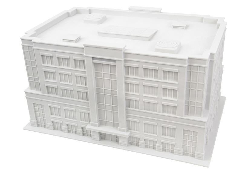 This is one reason – and a really good argument – for getting a 3D printer that has a much larger print bed. The fewer pieces you need the better.
A look at the assembled from corner …
… and a look at the assembled back elevations.
This process was extremely rewarding but we have a long ways to go before I would recommend to others that this is a viable design tool. In the two weeks we have spent on this, what I’ve learned is that it takes an extremely long time to create a finished-looking product, but there are significant ancillary benefits this process created within the firm.
There is no question that we will continue utilizing this tool – but I don’t think we will print out “finished models” unless they are actually finished and we are prepared to put some time in to clean up the surfaces prior to painting (or not) the surfaces. One of the interesting not-anticipated effects this process had was the amount of interest in the process that was generated.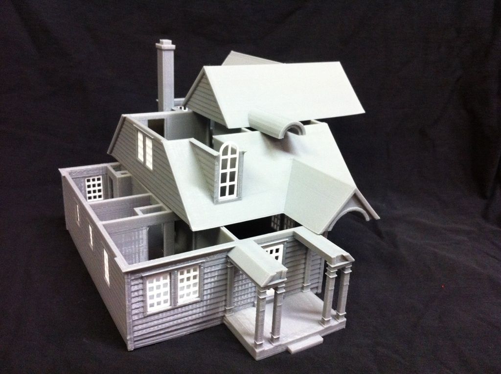 My office is constantly working on dozens of amazing projects at any one moment and we have to make an effort to show the entire staff what is happening on projects that they aren’t specifically working on – pretty easy to understand really. When we were printing out this model and had various parts strewn about our work area, dozens of people came but to check out what we doing and as a result, we basically explained the project to most of them along the way. I will also confess that I like the optics of printing out models – even hand-built models will work – because it helps support a design culture in the office. To that end, we prepared this model as a personal exploration into the process and not for the benefit of the client whose house we modeled. Sure, they will reap the benefits of us going through this process but this model was not a “deliverable” to them – it was purely a result of a process and effort of us trying to be better at our craft.
Cheers my friends –
even better stuff from Life of an Architect
Virtual Conventions??
Ep 078: Redlines
3D printing in architecture
3D printing has become an indispensable tool not only for large companies, but also for small architectural and design studios around the world. Why is 3D printers so popular? The reason is that 3D printing has become a real revolution in the field of building prototyping, design engineering and the creation of new creative objects.
- Why it's worth it
- Technology and materials
- Use cases
- Choosing a 3D printer
- Why is it profitable
- Technologies and materials
- Use cases
- Choosing a 3D printer
3D printing in architecture - why is it profitable?
Making architectural models is an important task for any design or architectural office. The quality of the model of the future project depends on the impression of customers, clients, potential investors. Prototyping by traditional methods is a long, laborious and very expensive process. 3D printing technology can significantly reduce the time needed to make a layout, improve quality, bringing it as close as possible to the original. At the same time, the main part of the design work is carried out on a computer using modern 3D modeling software.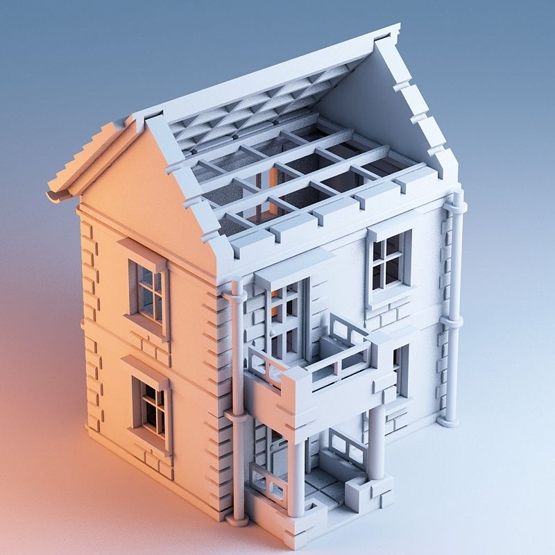
Advantages of 3D printing of architectural models:
- manufacturing speed - just a few hours of 3D printer work replace 2-3 months of manual labor;
- low production cost - uses a special available material based on VisiJet PXL gypsum;
- finished models do not require coloring, 3D printing completely repeats any shades and colors in the CMYK palette;
- high quality 3D printing: layer thickness from 90 microns, up to 390,000 colors, resolution 600x540 dpi; visual sample.
Technologies and materials
To create full-color architectural models , 3D Systems ProJet x60 series 3D printers are used. They are ideal for making bright, high-precision display models. ProJet x60 series 3D printers create CJP models from a special gypsum-based composite powder.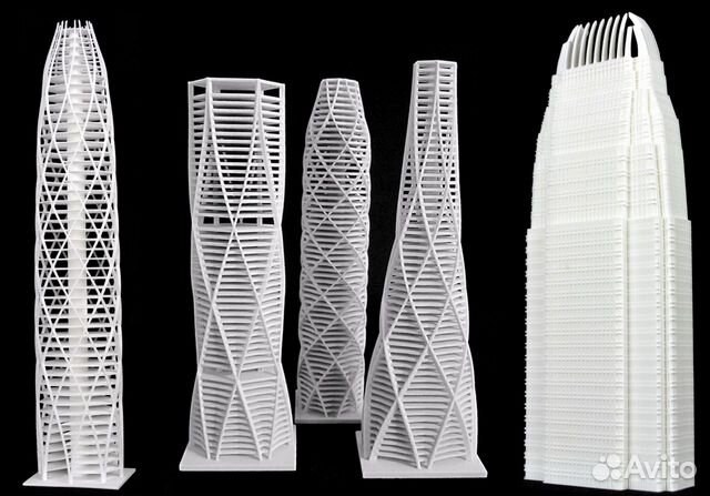 The main advantages of such systems are high productivity, quality and low cost of materials.
Full Color 3D Printers >>
In addition, large and complex mock-ups often use photoresin 3D printers. With their help, complex highly detailed parts of projects are made, with very small (less than a millimeter) elements. However, such 3D printers are not capable of printing colored objects, and the materials for them are much more expensive than gypsum.
Photopolymer 3D printers >>
Some architects and designers also use ABS 3D printers. This is Opportunity to save on the production of the layout, since the cost of plastic is lower than that of gypsum and photopolymers. However, it cannot be used to create full-color and highly detailed projects.
Technologies and materials
To create full-color architectural models , 3D Systems ProJet x60 series 3D printers are used. They are ideal for making bright, high-precision display models.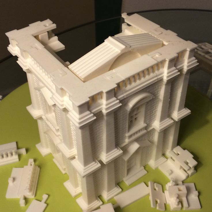 ProJet x60 series 3D printers create CJP models from a special gypsum-based composite powder. The main advantages of such systems are high productivity, quality and low cost of materials.
Full Color 3D Printers >>
In addition, photoresin 3D printers are often used to produce large and complex layouts. With their help, complex highly detailed parts of projects are made, with very small (less than a millimeter) elements. However, such 3D printers are not capable of printing colored objects, and the materials for them are much more expensive than gypsum.
Photopolymer 3D printers >>
Some architects and designers also use ABS 3D printers. This is Opportunity to save on the production of the layout, since the cost of plastic is lower than that of gypsum and photopolymers. However, it cannot be used to create full-color and highly detailed projects.
Full color mock-up created with a ProJet 660 Pro 3D printer.
Highly detailed resin building mock-ups.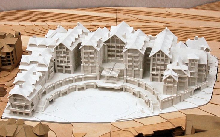
FDM house models
ProJet 660 Pro 3D printer in full color
Highly detailed resin building models.
FDM house models
Architectural examples of 3D printers
Ramboll wins tenders with 3D printing
Danish construction giant has been using 3D printers since 2004 to produce high-quality mock-ups for potential clients . This approach provided the company with a quick closing of deals.
Read more >>
Examples of 3D printers in architecture
Ramboll wins tenders with 3D printing
The Danish construction giant has been using 3D printers since 2004 to produce high-quality mock-ups for demonstrations to potential clients. This approach provided the company with a quick closing of deals. Picaso Designer XL series 20003
WHAT YOU WILL LEARN:
Strategies for designing 3D printed architectural models
Tips for improving your workflow Pre-print processing software
- Building information model (Revit, ArchiCAD)
- Surface modeling (Rhino, SketchUp)
Good post-processing techniques
- Compound
- Finishing
Introduction
The 3D printing market today offers affordable options in both price and scale.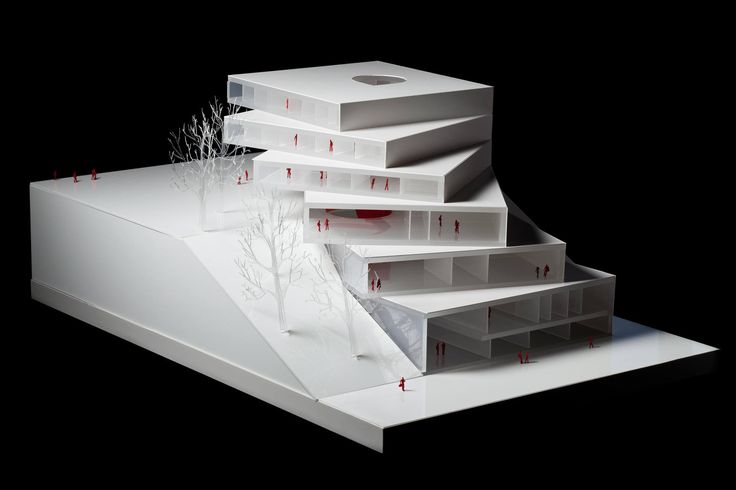 While professional-grade technology used to be costly, desktop stereolithography 3D printers allow architects, designers, and model makers to offer high-quality, in-house fabricated parts.
Most models cost less than $10 per part.
3D printing opens the door to creating complex designs with less effort and fewer materials, but the successful transition from CAD model to printable file is based on a basic understanding of design for 3D printing. This document will help you understand how standard modeling constraints relate to preparing a file for 3D printing, as well as approaches and decision making for intelligent modeling - from scale selection to design and assembly for post-processing.
To integrate these strategies into existing workflows, this booklet explores ways to approach modeling strategies tactically by examining three of the most common software ecosystems: allows you to include small details even on the smallest models. This example of a small town model is 1/32″ = 1’ scale and is 3D printed entirely on a Form 2. Many small details and parts of this design will take significantly longer if cut and assembled by hand. Model from LaneyLA Inc.
This auditorium section was 3D printed as one piece on a black resin Form 2. Model from DLR Group.
Modeling strategy
Architectural models are usually assembled using various materials and components. 3D printers help combine these components into as few separate parts as possible, but assembly manipulation is still necessary for two reasons:
- Build Volume Limitations : High build volume printers are either expensive or compromise on surface quality. Form 2 build volume is 57 x 57 x 69 inches (145 x 145 x 175 mm)
- Need to show interior details or materiality : Some models require components to be separated to show more design information.
DESIGN FOR ASSEMBLY
All 3D models require preparation before they can be sent to the 3D printer.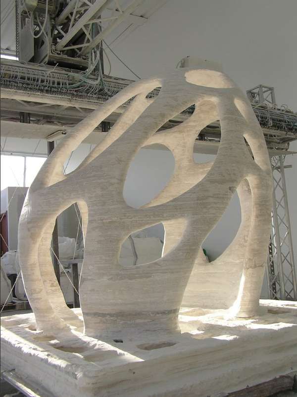 In the case of architectural models for the Form 2, this often involves splitting the model into smaller parts to fit the scope of the Form 2 build. The parts can then be easily joined together by chemical adhesive or mechanical assembly; high precision printing ensures that the parts fit together.
When choosing dimensions for parts to be separated, consider the final orientation of the model. Most architectural prints need to be oriented at a 45 degree angle due to floor slabs being considered large horizontal projections. Dividing the model into long, thin parts helps maximize the diagonal length of the build volume while achieving perfect orientation
Strategy overview
There are several strategies for assembling 3D printed models. Your strategy will depend on what you hope to represent with the design, as well as the scale and geometry of the model. Consider the following parameters:
- Need to show internal or external parts
- Easy Split (You want to split the model by the least complex part of the model)
It is necessary to show a certain part of the program: typology, structure, floor layout
| Seam separation | Separation by component |
| Section model | Separation by program |
| Straight cut | Separation by structure |
| Aligners |
Splitting at a seam
STRAIGHT CUT
The easiest way to split a model is with a straight cut.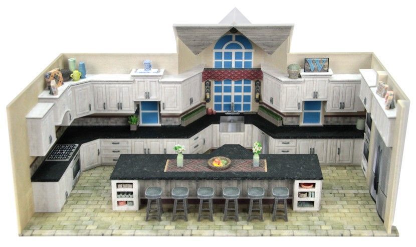 This is a simple command to execute in most CAD software. The bridge model is divided lengthwise using straight cuts into four parts, one of which is shown above. Each support post is inserted into
mating hole that does not require glue. Regardless of which method you choose, if you have a large number of parts (more than 10), it can be helpful to add a unique identifier for each part to help solve the puzzle during assembly.
Pros:
- Least heavy use of CAD
- Greater tolerance for prints that warp or have a higher degree of dimensional change
Cons:
- Assembly requires manually leveling each piece and fixing it in place until the adhesive is fully bonded
Try to print all components in the same orientation so that the layer lines and subsequent dimensional inaccuracies follow the same pattern.
ALIGNMENT TOOLS
Another approach is to add features to the design that will allow the prints to align. When adding mate fixtures, try to subdivide the model in areas with the least complex geometry. Use the CAD tool of your choice to split your model and add basic alignment fixtures such as slots, pins, grooves, recesses and flanges, or more complex fixtures such as dovetails and cuts that follow existing model curves. In addition, it is important to create a design with ~0.25 mm tolerance between mating parts to prevent additional sanding at the post-printing stage.
Pros:
- Easy alignment Parts that are not accurate
- Easy to assemble (mating parts help create more surface area for adhesion)
- High precision SLA allows tight fit with high tolerance and can be used without adhesive
Cons:
- Parts that are not true to size will not fit well. High fine details are often less accurate.
SECTION MODEL
The separation of the model with a seam has the additional task of showing the section model for structures with irresistible interior details.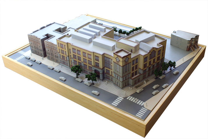 Initially, the model can be presented as a whole to the client, and then disassembled to reveal interior details as desired. These LaneyLA examples show how the same model conveys different types of information based on open and closed configurations
This model from LaneyLA was printed on a White Resin Form 2.
Using devices for combining: Methods component
SOFTWARE DIVISION
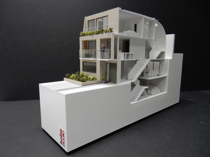
By splitting a building with software, you can represent the building as a set of parts, providing a clear understanding of all design components without a plan and section drawings. You can print each floor slab separately and then assemble using mates, or just print one component of the entire building separately from the rest. A good example is the model from Stanley Sitetowitz | Natoma Architects Inc (SSNAI), who used the Form 2 to model the residential complex.
Model by Stanley Sitetowitz | Natoma Architects Inc.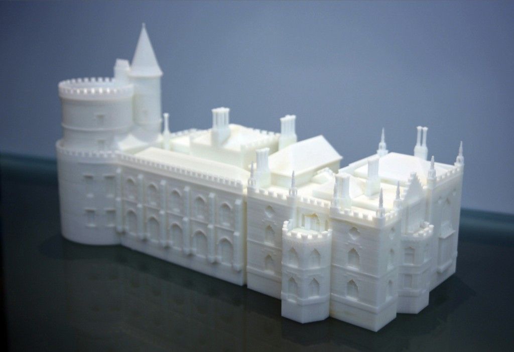
Since each body block followed the same pattern, it makes sense to simply print one detachable block that will allow the customer to understand the typology of the typical device to print as a single block or separate along the seam.
This method usually works for models that do not have straight lines, such as typical building blocks, but complex structures, such as detailed building sections, bridges, pavilions, or airports.
First, break these models down into components that can be 3D printed with minimal supports. This saves post-processing time (removing supports for delicate models can be tedious) and reduces material costs and print times.
This bridge example demonstrates multiple partitioning methods. First, the model is divided into several parts (Figure a). While they fit the
Form 2 build platform, they require painstaking removal of supports around more delicate areas such as cables and railings.
To solve this problem, each part is broken down into three sub-components: base plate and railing, vertical tensile cables, and solar panels on top (figure b). They can be printed with significantly fewer supports, making it easier to finish,
Once completed, the components simply need to be assembled using the alignment functions that were included in the design phase. Smaller parts are also easier to place on a single build platform, with the entire bridge being printed from five 100ml parts.
Model from T.Y. Lin Architects
This playground model was created using laser-cut fiberboard. The primary building was 3D printed from clear and white resin. Model by Schwarz Silver Architects
Materials
Materials play an important role in conveying the basic design concept. It is not always necessary to model the exact color and texture of a material, but it can help separate different materials. Dividing a model into its components allows for the display of materiality, as parts can be printed in different materials or individually dyed in different colors.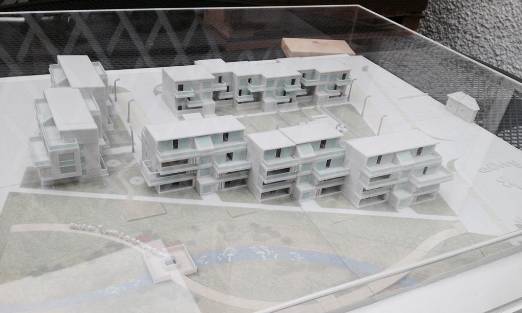
The transparent façade is illuminated from within, simulating the visual conditions of this site at night.
Formlabs Matte Resins
Black, White and Gray out of the printer have a smooth, opaque finish and provide an excellent neutral palette for architectural models. Gray and white resins are also easy to process and can be finished with just a few coats of paint, as discussed further in the finishing section of this document.
Formlabs Clear Resin is excellent for printing features that mimic translucent materials. If your model requires more transparency, you can simply dip the printed part in clear resin and let it dry evenly, as described in this article on making clear resin parts. You can also spray any clear coats on the model to increase the transparency and glossiness of the surface.
3D PRINTING AND TRADITIONAL MATERIALS
This model uses the Form 2 to print very fine details such as the cornice, clock and railing. Model by Miles Burke Architectural Models Inc.
Instead of 3D printing an entire building, sometimes it's better to print only complex components. Complex facades, slings and cornice details are excellent candidates for SLA 3D printing. Flat walls, floor slabs and topography can be laser cut or even hand-drawn
This complex façade is parametrically designed from solar trajectory analysis and would be incredibly difficult to fabricate in any other way at this scale.
Software Workflow
Good printing comes from a well-designed 3D model. This section will cover modeling best practices and workflows for printing in some of the most common CAD environments:
Revit, SketchUp and Rhino
CAD software is typically the bottleneck in the transition from drawing to 3D printed model
General workflows
IMZ workflow
IMZ workflow
2 901 PreForm
Although BIM (Building Information Model) software is popular with architecture firms, it is not always used for direct 3D printing models.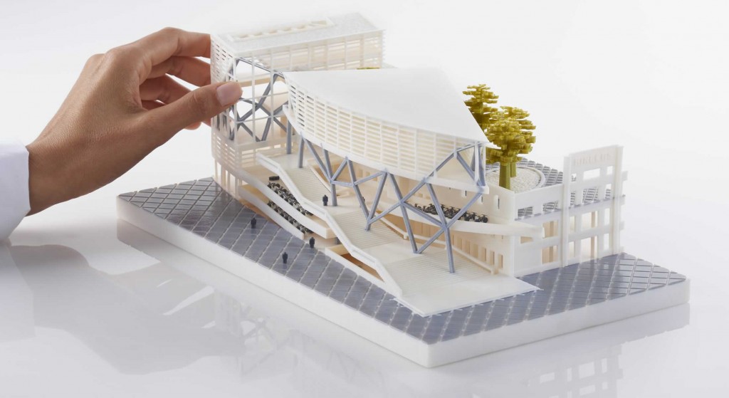 There are some high level steps that you can take
take to create a 3D printed model from these programs. This workflow is widely applied to Autodesk Revit or Graphisoft ArchiCAD software, both of which are IMZ parametric modeling programs.
PREPARE THE FILE
STEP 1: Prepare a separate offline file
STEP 2: Component Management: remove ducts, double glazing, HVAC units and internal parts that will not be visible in model
STEP 3: Select all components to be sealed (eg doors, windows, walls, slabs). The parametric nature of the model allows you to simultaneously compact the dimensions of several objects.
EXPORT FILE
Select the scale at which you want to export the file. Select the export options depending on the needs of your model:
EXPORT AS STL
Exporting the file as a mesh is very difficult to manipulate, so this is only useful if you don't want to edit any geometry after this step.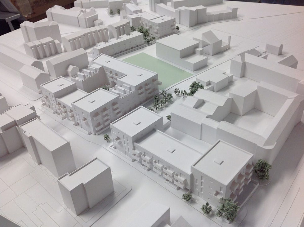 You can then use your software to correct the mesh of your choice, as well as subdivide the mesh along the main Cartesian planes.
EXPORT AS 3D DWG
Export as surfaces allows you to easily manage and edit geometry in Rhino or SketchUp. This step is recommended for those who want to split the model programmatically or by component, or split by a seam that is not on the normal Cartesian plane. You can then export the STL file from Rhino or from SketchUp using the plug-in
EXPORT USING ARCHICAD
Perform a geometry transformation to Morphs and a "consistency check" before exporting the model as STL. When printing in parts, use tool
"Divide" to cut the model for multiple platforms, if needed. This operation basically creates printable files, but a quick check in mesh repair/analysis software never hurts.
USING STL REVIT EXPORTER
This method automatically removes smaller details such as doorknobs and railings. However, it is not reliable and still often requires some post-processing in other CAD environments before being sent to print.
Surface Modeling Workflow
AutoCAD → Rhino/SketchUp → Model Diagnostics → PreForm
This workflow is often an easier approach and starts with 2D drawings purely for the purpose of 3D printing
STEP 1: Hide unwanted layers
STEP 2: Identify and remove unwanted elements such as furniture, trees, etc.
EXPORT FILE
STEP 1: Export the simplified drawing from Rhino as DWG
STEP 2: Import into Rhino
STEP 4: Start extruding and trimming until you get the outer shell.
STEP 5: Export as STL STEP 6: Mesh Analysis/Correction STEP 7: Import to PreForm
Note: If the model will be printed in several parts, split it before exporting as STL
THIN WITH RHINO
Instead of parametrically controlling the thickness of components directly in the BIM file, you can also use the BoxEdit component in Rhino.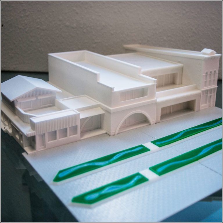
This allows you to simultaneously scale a number of elements in relation to their center lines. BoxEdit is ideal for models that need to be scaled parallel to three Cartesian axes. Non-uniform scaling is a little trickier.
For non-rectilinear geometries, we suggest converting the part to a mesh and then using the Weaverbird thicken command, which simply offsets any non-standard mesh geometry outward by a given distance. Alternatively, it is possible to "split" complex parts into surfaces and then offset them instead of importing volumes from Revit.
SELECTING SMALL GEOMETRIES WITH RHINO
Another valuable Rhino feature is the SelSmall command, which allows you to select all elements in the Stage that are smaller than a custom bounding box. You can then select those objects and use
BoxEdit for individual scaling or just remove them. This is useful when you are dealing with a file that does not have a well organized layer system.
Although performing a logical connection on all geometries is ideal, often the problem can be solved with simple overlapping geometries. PreForm will interpret them as one closed geometry in most cases, but be sure to check printability with the "slicer" tool in the right pane in PreForm
. CONTINUOUS / LOGICAL JOINT GEOMETRY
Note : PreForm is Formlabs free software that prepares your 3D model for printing in Form 2. Once the part is set up, you can save it as a FORM file for future use in preform.
COMPUTATION WORKFLOW
Although a less common workflow, computational design is slowly being introduced into mainstream architectural workflows. Software such as Grasshopper and Dynamo are used to create parametrically generated geometries that are often so complex that they can only be created with 3D printing.
Since geometries are already easy to manipulate, it's usually best to create a separate component that allows you to easily control the basic dimensions of all thin objects.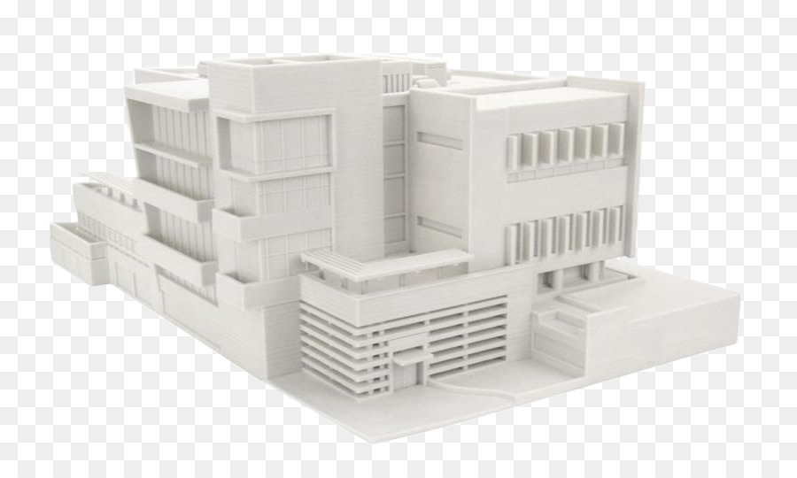 In this case, it's a simple matter of trial and error; running the exported geometries with a print test (PreForm,
MeshMixer) and resizing until you arrive at a printable file.
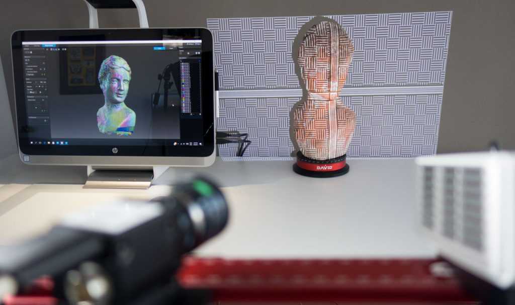
Model Diagnosis
All workflows described below share a potential "generic diagnosis". This is an optional (but often necessary) step to ensure that the model is fully printable. Free programs such as Autodesk's MeshMixer and Netfabb are tools that allow you to repair, smooth, cavity, and split 3D print files.
MESH FIX
Formlabs PreForm software uses Netfabb's built-in mesh fix, so NetFabb and MeshMixer must be used for custom fixes or to preview problem spots in print. Materialize Magics is a great proprietary tool that covers the entire preprint workflow for a wide range of printer types. The mesh patching software part is most important to the Form 2 print workflow and can save you a decent amount of preparation time. Netfabb has a beautiful built-in model cutter that allows you to effectively split and restore large files along any Cartesian plane.
SPLITTING THE MODEL
It is also possible to split the model in NetFabb, which splits and fixes the split parts into printable volumes. In Rhino, you will need to close open volumes. Be sure to leave a tolerance of ~0.25mm between adjacent parts, this will allow them to be inserted without friction.
See our white paper for tolerances.
PREFORM SLICER
Architectural models are highly detailed and it is often difficult to isolate each print issue. A combination of the above practices and mesh repair software is usually used for almost all problems, but it's always wise to use the PreForm Slicer tool to make sure there are no thin unsupported areas and enclosed volumes (such as rooms with no doors, elevator shafts, and parking spaces) .
“Building and architecture structures are not meant to be 3D printed, they are meant to be built. This creates problems of scale and complex geometry. By combining Netfabb's powerful mesh repair tools with the precision of the Form 2, you can prototype and visualize designs faster and in more detail, benefiting more for your business and speeding up your project's design review process.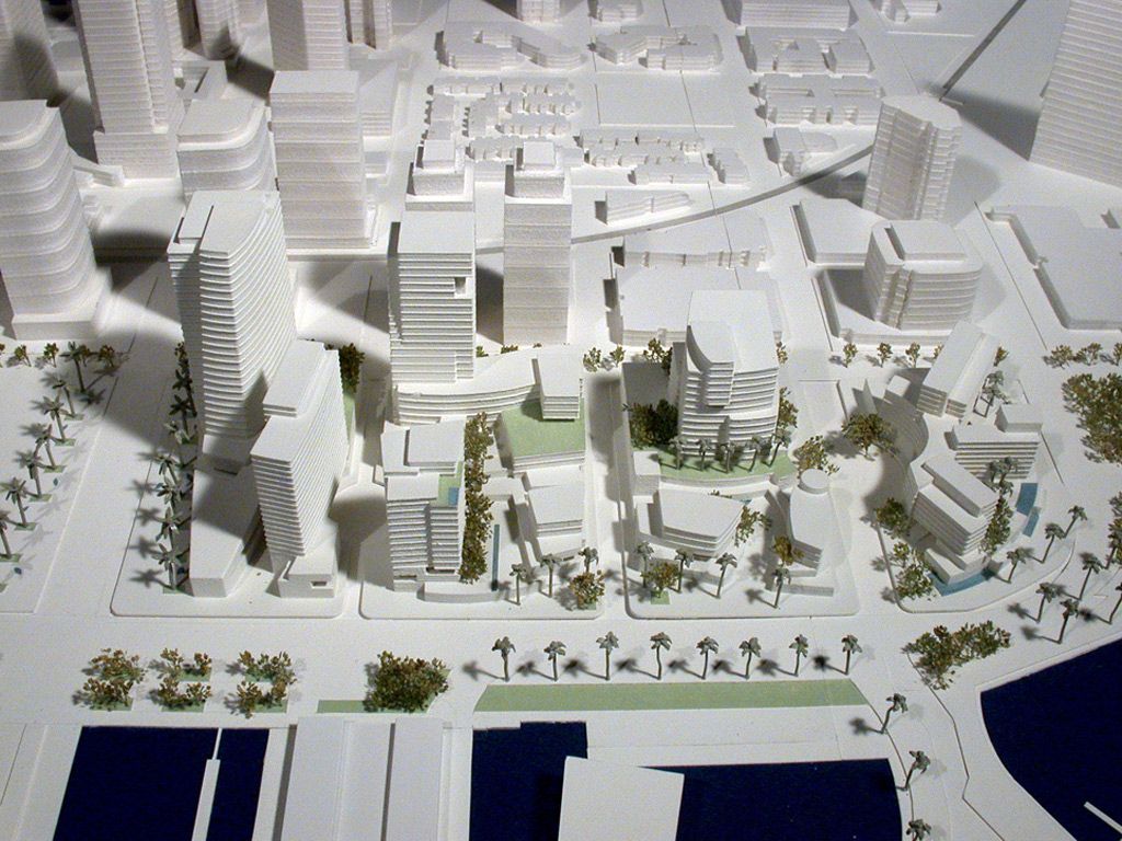 ”
”
Matt Lemay. Lead Enterprise Solutions Provider, Autodesk Customer Service
Post-Processing
Joining
The Modeling Strategy section of this booklet covers some ways of splitting and aligning parts together, but glue is always needed for a secure connection. Architectural parts are bonded in two main ways:
CYANOACRYLATE
Cyanoacrylate (CA or Super Glue) creates a fast, strong enough bond, ideal for small to medium sized parts. CA does not bond dirty surfaces well, so be sure to thoroughly clean the part before applying adhesive to the surface of the model.
POLYMER
For smaller prints, you can use liquid resin as a binder. Dispense a small amount of resin into the tray from a bottle or cartridge, use a dropper or syringe to lift it up, and place it on the surface of the part to be bonded.
Join parts and wipe off any excess resin that may be spilling around the edges.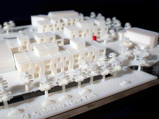 To cure the resin and bond the parts, use a 5 mW laser pen at 405 nm and point it at the bonding area around the parts.
This method creates a chemical bond, just as if the part had been printed on your SLA 3D printer, but only applies to small bonding surfaces because a low power laser pen cannot penetrate the model deep enough to create a strong bond .
FINISHING
Parts printed on Form 2, especially matte standard resins, have a smooth surface as soon as they exit the printer. However, visible areas with supports almost always require sanding. In addition, you can prime and paint parts in any desired color.
GRINDING
Sanding will help you remove the support marks and any remaining inaccuracies from your model. Start by carefully dry sanding the surface of the part using ~150 grit sandpaper to remove large support marks and smooth out the edges of the joint. Once the surface of the part is smooth, wet sand with 320mm sandpaper to remove any remaining layer lines.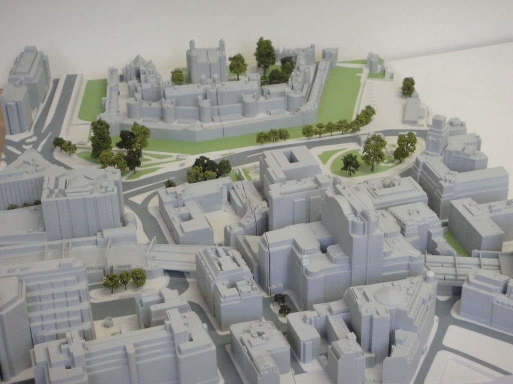 Move the sandpaper randomly to avoid grain formation.
In most cases these two steps will create a fairly even finish, but you can continue to increase the grit size of the sanding paper by a factor of 2 and wet sand the entire piece until the surface is smooth enough.
Once you have finished sanding your model, wash the model in soapy water to remove dust or debris and dry thoroughly before proceeding to the last step.
The architectural models are very detailed and it is quite difficult to access certain areas with only sandpaper. You can use different sizes of nail files to get to problem areas of the model.
PRIMER AND PAINTING
Priming is required before parts are painted to ensure the paint adheres to the surface. Priming can also make it easier to find areas that require additional finishing. A quick spray of primer over the model makes the support marks very visible, so you can instantly identify areas that need additional sanding.