Arc welder 3d printer
Arc Welder
Anti-Stutter and GCode Compression. Replaces G0/G1 with G2/G3 where possible.
Makers Mashup Review of Arc Welder The Arc Welder TabHow To Use Arc Welder
Please read the readme file in the Github Repository for installation and usage instructions. I am planning to add a complete wiki for the plugin in the near future and will link to that here when it is complete.
Please note that if you are using Python 3, you may need to install the python3-dev package before Arc Welder will install. This is detailed in the prerequisites section of the readme file linked to above.
Support
Arc Welder DevelopmentPlease consider supporting my work by becoming a patron, a Github Sponsor, or by sending me beer money via PayPal. Almost all of the donations go towards offsetting the cost of development, which is substantial. Plus, it always makes my day! If you cannot afford to leave a tip or just don’t want to, that is fine too! Arc Welder is free and open source after all.
What
Arc Welder DoesArc Welder attempts to replace G0/G1 (linear move) GCodes with G2/G3 (arc move) GCodes. This can substantially compress many GCode files and may reduce stuttering caused by sending many tiny movements in rapid succession over a slower serial connection. Here is an example of the before and after of a single layer of a cylinder with archimedean infill produced by PrusaSlicer:
Before: GCode generated by PrusaSlicer. After: GCode processed by ArcWelder. Visualized with ncviewer. View the Full Sized Image.Each dot in the image above represents the start or endpoint of an extrusion. You can see that the After GCode above has far fewer moves. The processed GCode is 76.1% smaller with 96.4% fewer extrusion/retraction commands than the original file. Detailed statistics are created and stored for each GCode file processed:
Statistics of the arc-welded file, showing a substantial reduction in file size and extrusion/retraction moves.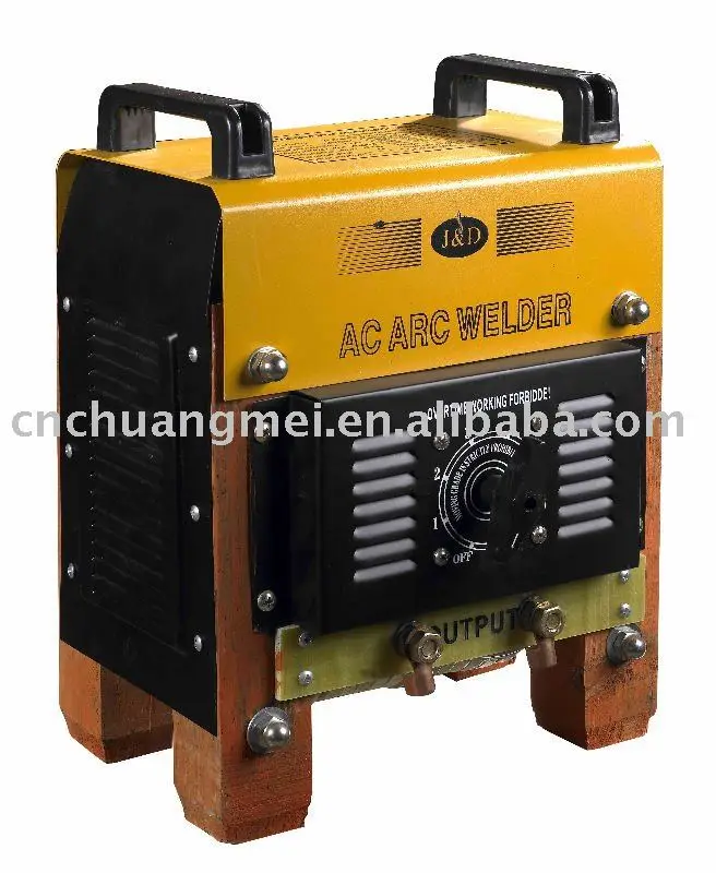
The results above are not typical since the source file is almost entirely circular. A better real world example, the first layer of the famous 3DBenchy, sliced with PrusaSlicer using archimedean infill is shown below:
Before: GCode generated by PrusaSlicer. After: GCode processed by Arc Welder. Visualized with ncviewer. View the Full Sized Image.The result is a GCode file that is 56.2% smaller (2.3 compression ratio) with 75.0% fewer extrusion/retraction commands. In this case, Arc Welder shows a massive decrease in small extrusion moves between 0.01mm and 1mm in length:
Min Max Source Target Change -------------------------------------------- 0.000mm to 0.002mm 0 0 0.0% 0.002mm to 0.005mm 0 0 0.0% 0.005mm to 0.010mm 0 0 0.0% 0.010mm to 0.050mm 7 1 -85.7% 0.050mm to 0.100mm 29 6 -79.3% 0.100mm to 0.500mm 1342 74 -94.5% 0.500mm to 1.000mm 810 114 -85.9% 1.000mm to 5.000mm 145 341 135.2% 5.000mm to 10.000mm 1 25 2400.0% 10.000mm to 20.000mm 2 14 600.0% 20.000mm to 50.000mm 8 8 0.0% 50.000mm to 100.000mm 2 2 0.0% >= 100.000mm 2 2 0.0% -------------------------------------------- Total distance:............1929.879mm Total count source:..................2348 Total count target:...................587 Total percent change:................-75.0%
How
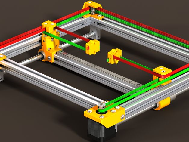
Arc Welder WorksArc Welder reads each GCode in the source file, searching for three extrusion or retraction commands in a row. It adds adds these points to a special shape detection class that determines if the collected points can be represented by an arc command (G2/G3). Once an arc is detected, Arc Welder compares the original GCode path with the resulting arc command to ensure that any deviation is within the specified resolution (by default, +-0. 025mm). Arc Welder will continue to add new points to the arc until it detects either a significant deviation from the original GCode or a change in the printer’s state (a new layer, a feedrate or offset change, etc.). It will then pull off the final point from the arc, output the altered G2/G3 command, and continue to process the file. The resulting GCode will not vary from the source file by more than half of the specified resolution, which is configurable. Here is a rudimentary illustration:
In the example above, Arc Welder has created two arcs. The first arc starts at P1 and ends at P5 on the blue line. The original path is shown in red. In this example Arc Welder first adds three consecutive points (P1-P3) to its shape detection class and determines that the generated arc does not deviate significantly from the original path. It then adds P4 and P5, again detecting no significant deviation. However, at P6, the detected deviation exceeds the maximum, so P6 is not added, and an arc is generated that replaces P1-P5. Arc Welder then starts a new arc from P5, P6, and P7 and continues the process. Note: The endpoints of every arc will ALWAYS line up exactly with the original GCode.
It is important to note that the example above is zoomed WAY in so that the deviation looks very large. It is, in fact, extremely small and almost impossible to see with the naked eye. You can customize the resolution in the plugin settings if 0.05mm (+- 0.025mm) is too large for you.
Arc Welder Plugin Features- Customizable Resolution - You control the maximum allowable deviation from the original tool path. Higher values will result in more compression but more deviation. Lower values will produce more accurate GCode but less compression. The default value of 0.05mm (+- 0.025mm) produces excellent results in most cases. I would recommend a lower value only for extreme cases, like extremely high resolution models with small nozzles and very low layer heights.
 Values higher than 0.05 are not recommended.
 - Automatic and/or Manual Processing - Arc Welder can be configured to automatically process newly added file or to allow manual processing via an integration with the OctoPrint file manager. You can enable one or both of these methods depending on your preference.
- Rename or Overwrite the Source File - Choose to keep the original source GCode file or replace it entirely with the arc-welded file. You can also add a custom prefix or postfix to the output file.
- Delete the Source File After Processing - You can create a new file and have Arc Welder delete the original file automatically in most cases.
- See Detailed Conversion Statistics - Arc Welder creates and stores statistics for each converted file, including compression percentage and ratio, source/target file size, and line count, as well as a detailed comparison of extrusion/retraction counts at various lengths between the source and target file.
 You can view statistics for any arc-welded file by selecting it in the file manager or by clicking on the icon within the file manager.
 - Detailed Conversion Progress Bar - See real time progress info as Arc Welder processes your file, including several useful statistics. You can cancel the conversion at any time.
- Enable/Disable Notifications - Tired of popup messages? Turn them off in the settings.
- Advanced Logging Settings - You can control logging from within the plugin’s settings page if you run into problems. You can even delete the existing log(s) completely.
- Restore Plugin Defaults - Easily restore the default settings if you run into trouble.
- Receive Notifications for New Development or Maintenance Release Candidates - Get early notifications about new features and bug fixes. Help contribute to the project! Arc Welder also supports plugin-specific release channels in a future version of OctoPrint (if that feature is eventually released).
The core of the Arc Welder plugin is a set of libraries written in c++ based on code that was originally designed for the Octolapse plugin. This code allows Arc Welder to parse GCode and determine the printer’s position and extruder state after each command. Since the code is written entirely in c++, it is orders of magnitude faster than similar code written in Python. The complete source, as well as a console version and inverse processor (convert G2/G3 to G0/G1), can be found here. There are also pre-compiled binaries, though I’ve not gotten them to work properly in MacOS or in some flavors of Linux. There are currently no GitHub hosted runners for any Raspberry Pi. I am working on these issues.
Using the console application, it is possible to arc-weld files via most slicers as a post-processor. However, all slicers that I have tested except for Simplify 3D fail to correctly visualize the G2/G3 commands.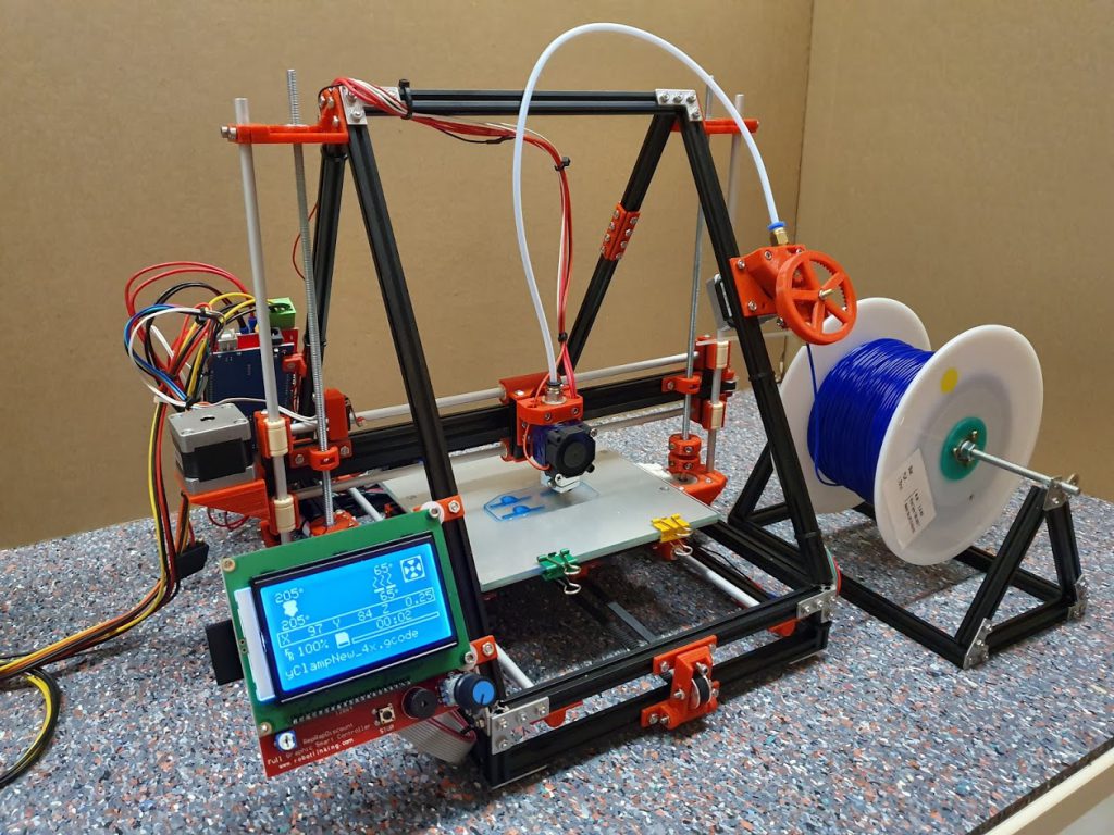 Simplify 3D does seem to work perfectly for this, but other slicers make it look like the GCode is faulty. Keep that in mind if you plan to integrate the Arc Welder Console Application with your slicer.
Firmware Considerations
Your printer’s firmware must be capable of printing G2/G3 commands to use the GCode produced by Arc Welder. Additionally, arc support must be enabled and properly configured. Firmware support varies, and many older versions produce arcs less accurately and more slowly than expected.
Marlin
Marlin has supported arc commands for a long time. However, starting with version 2.0.6 arc support has been greatly enhanced. I recommend you upgrade to at least this version before using Arc Welder because your experience will be much better. Arc support must be enabled in your Configuration_adv.h file.
For recent versions of Marlin (2.0.6 and above), you can send an M115 to see if your firmware has ARC_SUPPORT enabled. For earlier versions you can send an empty
 G2 or G3 command. If your printer responds with unknown command, arc support is not enabled.
If your printer is running a fork of Marlin, but arc support is not enabled or is buggy, I recommend creating an issue within the fork’s repository.
“A plugin that can convert curves into arcs will be massively welcome and should make a great improvement in performance and print results.”
Scott Lahteine- Creator of Marlin Firmware
Prusa Firmware
Prusa’s fork of Marlin does support G2/G3 commands, however the default settings can produce sharp corners for very small arcs. I’ve only noticed this in a few of my test prints, so it is not a particularly common issue. You should be able to see it on the roof of a Benchy if you look closely. Reducing the MM_PER_ARC_SEGMENT setting slightly can correct this but can also introduce stuttering. Reducing the value massively (say to 0.1mm) will introduce a LOT of stutter and is NOT recommended. Please note that adjusting this setting currently requires a manual firmware recompile.
I have been toying with the firmware and have submitted a pull request to enhance the capabilities, but it hasn’t made it into the firmware yet and may require further modifications. I am planning to add some enhancements from Marlin 2.0.6 as well. I also added some new GCodes for adjusting arc interpolating and for retrieving the firmware settings for arc generation. You can view the pull request here. Feel free to give this pull request a thumbs up, but realize that it needs some work and that the good folks at Prusa Research have a lot on their plates.
Also, some very old versions of Prusa’s firmware (I’m not sure exactly how old) do not support bed leveling adjustments during arc movements. Please make sure you are using a recent version of the firmware so that interpolated movements are properly leveled.
Klipper
Klipper seems to handle G2/G3 commands with ease, as long as the GCode_arcs config section is enabled. G2/G3 support was added on September 13, 2019, so make sure you update Klipper if you are using an older version.
Other Firmware
Though G2/G3 support is not universal, nor are all implementations equal, it is relatively easy to test. You can do so in the OctoPrint terminal by sending the the following commands, one at a time:
G90 G28 X Y G0 X0 Y0 G2 X40 I20
If your printer supports arc commands, it should move across a small arc from the origin. Please feel free to let me know if your firmware supports arc movements, and I may add it to the list.
Warning: The above GCode has not been tested on all printers. Please use it with caution and report any issues here.
Other Firmware Considerations
Most firmware will convert G2/G3 commands to many small segments through a process called interpolation. The length of these segments varies by implementation. In most cases the interpolated segments are much closer together than the linear segments you will find within your GCode file, but it’s impossible to know for sure without examining the firmware in detail.
All firmware that I am aware of will inscribe these interpolated segments within the arc. These segments will be entirely within the arc, only touching it at the endpoints. This will reduce the average radius slightly. In most cases, this effect is minimal and has no practical impact. However, in some odd cases, like a snap fitting that is extremely sensitive to changes in diameter, the effect may be noticeable. The smaller the interpolated segments (all firmware controlled), the less of an effect there is. In general, it will be a much smaller effect than normal variations in filament diameter. I hope to find a solution to this problem.
G2/G3 support is not perfect at the moment, but I suspect things will start to improve as they become more common. If you are willing and have the skills to improve G2/G3 support in any way, please do!
License
View the Arc Welder license.
What Is the Arc Welder Plugin for Cura? (How to Install?)
Last Updated: September 2, 2022
There is no denying that Cura has established itself as the most popular slicer in the 3D printing community for a while now, offering a complete experience with its many features for obtaining high-quality prints, its clean interface that improves the user experience by a great deal, and its community that makes it easy to resolve any problems one may face.
Among everything that Cura offers, a specific feature especially stands out, which is its plugin support that practically allows Cura’s feature set to be extended unlimitedly by the members of the community, making Cura a piece of software that is ever-evolving, even when the developers aren’t actively adding new features.
In today’s article, we will be examining the Arc Welder plugin for Cura, in specific, which brings some significant functionality to 3D printer movement, and as a result, has a sizeable number of downloads on the Ultimaker Marketplace, where Cura plugins made by the community are listed.
So, what is the purpose of the Arc Welder plugin for Cura?
The Arc Welder plugin for Cura automatically combines subsequent linear moves (with extrusion <G1> or without extrusion <G0>) and converts them to arc or circle moves (clockwise <G2> or counter-clockwise <G3>) to optimize the G-code and make the curved motions much smoother for the 3D printer.
Next up, we will dive deeper into the functionality of the Arc Welder plugin for Cura, find out how to install the plugin and how to use it efficiently, and finally, discuss the scenarios where it would be appropriate to utilize this plugin to improve our 3D printing experience.
Table of Contents
What Is the Arc Welder Plugin for Cura?
While the Arc Welder plugin is entirely optional and not a necessity to be able to use Cura by any means, it brings some significant improvements to the table regarding how your 3D printer performs specific movements during the printing process.
Arc Welder, which is a community-made plugin for Cura, aims to optimize the G-code file that Cura produces by combining linear move commands (G0 and G1) and turning them into arc move commands (G2 and G3) whenever possible, creating a more compact G-code file by reducing the total amount of commands.
The primary benefit of this conversion is to prevent the 3D printer from stuttering, which may occur due to the 3D printer reading and completing the execution of a G-code command before the following command arrives for consumption, with the issue being commonly known as the buffer underrun problem in computing.
On the other hand, it’s also worth mentioning that your 3D printer may not be able to perform as well as it has with the linear moves in the case of printing arcs due to various reasons, which can result in a drop in quality in your 3D printed models in some cases.
How to Install the Arc Welder Plugin for Cura?
Installing the Arc Welder plugin for Cura is almost a zero-effort process thanks to the Ultimaker Marketplace, which is a built-in section in Cura that allows you to directly access all the community plugins and install them with a few button clicks.
Below is a step-by-step guide you can follow to install the Arc Welder Plugin for Cura through the Ultimaker Marketplace.
- Click the Marketplace button on the top-right corner of the Cura window.
- Scroll down in the Community Plugins section to find Arc Welder, and click its icon.
- Click the corresponding Install button to start the installation process of the Arc Welder plugin.
- Accept any pop-up dialogs that appear for the installation process to continue, and wait for the installation to conclude.
- Restart Cura for the Arc Welder plugin to be loaded.
After you restart Cura, the Arc Welder plugin will be installed and ready to use. To confirm that the plugin is indeed installed, you can navigate to the Marketplace section again and inspect the Installed tab, which allows you to see all of your installed plugins.
As the Marketplace section requires you to have an Ultimaker account, you will need to create one for free if you haven’t done so before and log in to it before you can install the Arc Welder plugin to Cura.
How to Use the Arc Welder Plugin for Cura?
Just like installing it, activating and configuring the Arc Welder plugin for Cura is also very straightforward since the plugin directly integrates itself into Cura’s menus, allowing you to have access to everything in a single place.
Below are the steps you can follow to activate and use the Arc Welder plugin for Cura after you have successfully installed it:
- Navigate to the Prepare tab of Cura, located at the top of the window.
- Click the pane on the right to bring up the Print Settings dialog.
- Click the Custom button if you see it; else, skip this step.
- Click the icon next to the search input, and choose the All option from the dropdown. This process will make all configurable parameters of Cura to be become visible, including the toggle for the Arc Welder plugin.
- Type “arc welder” into the search input and press Enter.
- Check the box next to the Arc Welder label.
Following these steps will enable the Arc Welder plugin and allow the plugin to perform the optimizations it offers to your G-code file automatically, without the need for any extra steps on your part.
Wrapping Up
While it’s perfectly possible to achieve high-quality prints without utilizing any plugins in Cura, the Arc Welder plugin and many other plugins make the 3D printing experience a lot smoother with the improvements they bring to the table without requiring the user to spend any effort or time.
To quickly recap, the Arc Welder plugin’s purpose is to perform automatic optimizations to the G-code that Cura produces by finding successive linear moves (G0 or G1) and combining them into arc (G2 or G3) moves, creating a more optimized G-code file that will be easier for your 3D printer to handle.
As the Arc Welder plugin does everything automatically without the need for any extra tuning (unless you would like to perform advanced configuration), you won’t need to do anything other than installing it in Cura for the first time and enabling it through the Print Settings section.
Happy printing!
Mike Davies
Mike started his 3D printing journey with the Anet A8 when it first came out back in 2017, and has been obsessed with 3D printers ever since. Nowadays, he primarily uses his Ender 3 to print functional parts that make his life more convenient whenever possible.
SPbPU has developed a technology for 3D printing by electric arc growth
News
Specialists of the Laboratory of Lightweight Materials and Structures of Peter the Great St. Petersburg Polytechnic University (SPbPU) have developed a domestic analogue of 3D printing technology using the arc welding method. The use of metal wire as a consumable material significantly increases productivity and reduces the cost of finished products.
According to the press service of the university, the work is carried out within the framework of the federal target program. The technology in Russia does not have a clear technological name, as well as abroad. For example, Dutch and British developers working in a similar direction called the technology "WAAM" or "Wire+Arc Additive Manufacturing" ("Additive manufacturing by arc welding of bars"). The German company Gefertec GmbH calls the process "3DMP" ("3D Metal Print"), while the St. Petersburg developers settled on the working name "Electric Arc Growth".
The basic principle of the technology is simple: it is the same arc welding, but in three dimensions. The printhead, typically mounted on a robotic arm, feeds the metal bar and fuses it onto the substrate or previous layers at the same time. The advantage of this technology in comparison with powder systems is the low cost of consumables (10-20 times lower than the cost of fine powders of the same composition and weight), high productivity and almost unlimited scalability. The main disadvantage is the need for intensive mechanical post-processing of the surfaces of the resulting products.
“A lot of things in the world have not yet been done, but we have already tested this technology on a fairly large number of aluminum materials. For four of them, complex studies were carried out. Our competitors tend to use specific and expensive arcing power supplies. We managed to do it on cheap components and significantly reduce the cost of the finished product,” says Oleg Panchenko, head of the Laboratory of Lightweight Materials and Structures.
The technology, in principle, makes it possible to work with almost any metal or alloy in the form of a wire, provided that welding is carried out in a protective gas flow. For shipbuilding, steel and bronze are considered, for aircraft building - aluminum, titanium and heat-resistant nickel alloys. By feeding several materials at once, intermetallic structures can be obtained. The Dutch company RAMLAB is already applying electric arc growth technology in the production of ship parts. So, in December last year, the first 3D-printed propeller was type-certified. Another Dutch company, MX3D, is preparing to decorate Amsterdam with the world's first 3D printed steel bridge ( in the illustration above ). How it works, see the video:
Do you have interesting news? Share your developments with us, and we will tell the whole world about them! We are waiting for your ideas at [email protected].
Follow author
Follow
Don't want
3
More interesting articles
ten
Follow the author
Subscribe
Don't want
German startup iFactory has announced the third model of the FDM 3D conveyor with unlimited...
Read more
6
Subscribe to the author
Subscribe
Don't want
Specialists of the Skat 3D Prototyping and 3D Printing Center launched additive manufacturing of orthopedic. ..
..
Read more
59
Subscribe to the author
Subscribe
Don't want to
The 3Dtoday portal, supported by Creality and Bestfilament, invites everyone to participate in...
Read more
Fire and wave: all about metal 3D printing 900 9002 Everyone knows this: 3D printing today is one of the pillars of world technological progress. It's just a pity that news about revolutionary developments in this area rarely comes from Russia.
The more pleasing are the exceptions. Scientists from the Bryansk State Technical University (BSTU), with the support of the Advanced Research Foundation, have created an installation (the Taimen project), which has become a truly new word in metallurgy and metalworking.
Among the great variety of additive technologies that exist in the world, two are clearly in the lead - printing with molten plastic and laser sintering of metal powder. In the first case, a low-melting plastic thread is fed to the print head, the tip of the thread heats up and instantly turns into a drop of liquid melt, which is applied to the desired point of the formed product and soon solidifies. It would be nice to print with metal as well, but metal is not plastic or wax. How to create such a temperature in the print head that it instantly turns steel into a liquid? I had to first invent laser sintering for metal printing.
Welding prints
And then the answer was found. Within the walls of BSTU, for a couple of decades, the technology of 3D printing with metal using ... electric arc welding has been developed and improved. Here, almost everything is like in a plastic printer: instead of powder, there is a metal thread fed to the printing point, or simply wire (welders call it filler material). An electric arc discharge melts the filler material and places a drop of metal in a precisely defined place. “Arc welding is only the basis of our method,” says Andrey Kirichek, project manager, professor and vice-rector of BSTU. - In fact, we have to solve a very atypical task for welding work - to give a shape to a printed product, to build up walls. It is impossible to do it manually: we need automation and programmatic control of the process, which we did. On the other hand, there is an opportunity to use the experience gained in the field of welding. Devices and equipment for welding are mass-produced and inexpensive.”
Impact on dendrites
3D metal printing technology using electric arc welding has serious prospects. Bryansk developers have competitors from Germany, the USA and Norway, and all these companies are experiencing rapid growth. Being at the forefront is already worth a lot, but Russia has managed to advance the farthest. The fact is that in addition to the additive module, which is actually engaged in growing the product, the domestic installation includes a hardening module. In the standard case, the part printed on the printer will have the crystalline structure of a conventional cast product. But if the build-up layers are periodically compacted with shock pulses, turning large dendrites into colonies of microstructures, then the strength of the part will seriously increase. In the case of austenitic steels, for example, the yield strength of the material increases by 2–2.5 times, and the tensile strength by 1.5 times. This makes it possible to use cheaper alloys. The hardening module is a generator of mechanical impulses, through which a deformation wave acts on the metal - this has a positive effect on the crystal structure, mechanical and operational properties of the hardened metal.
Work on the use of strain hardening in additive technologies at BSTU began about five years ago, and at the same time the FPI became interested in this problem, with the support of which a special laboratory was created at the university. Today, there is not a single company in the world that would produce equipment that combines the processes of growing a product by welding and wave strain hardening.
The third module of the installation in question is the milling module, which provides, if necessary, machining of the part. “It must be admitted that, compared to laser sintering, our product formation technology is somewhat rougher,” Andrey Kirichek explains, “but even the most advanced “powder” printers give an error of at least 0.1 mm, and for precision mechanics (for example, in gas turbine) is too much. Therefore, machining, which ensures high accuracy of forms, is still indispensable. The advantage of our installation is the ability to alternate the operation of the modules as required. For example, to grow only a part of the product in order to process its internal surfaces that are hard to reach in the final form.
And cheaper, and our
Due to the greater accuracy, laser sintering technology is better suited for medium-sized complex-shaped parts with internal cavities, thin ribs, etc. But there are many large-sized products that also need to be grown. In this case, considerations of economy or scalability come to the fore. And here the new technology has a lot of advantages. Laser sintering is a very expensive technology, and the powder itself is especially expensive. Companies that produce sintering equipment configure it exclusively for powders of their own production. The range of powders even from well-known companies is small. In Russia, they are not produced on an industrial scale, and this greatly limits the capabilities of the technology. Plus, the welding method has a productivity about 6 times higher. And most importantly, it is not economically feasible to produce any large part by sintering, but it is quite possible and profitable to create an installation for printing and hardening metal beams of complex shape.
Like a hammer, only better
It is interesting to compare the technology of wave work hardening with traditional forging, because the goals and methods of these processes are generally similar. “Indeed, deformation and hardening occur here and there,” says Andrey Kirichek, “but in our case, energy enters the deformation zone in the form of a wave. A wave is a stream of impulses that have duration, amplitude, and shape. When forging, the pulses are short and rare; many processes that can change the structure of the metal simply do not have time to go through. We work with prolonged (10 times longer) pulses with a frequency of 8 to 40 Hz, the impact on the material is long-term, the efficiency of the impact energy on the elastic-plastic deformation of the hardened material is 5-10 times higher compared to a conventional impact and reaches 65% . With a simple impact, this figure is only 5–12%.
The part is created using three modules - additive, hardening and milling. The peculiarity of the process is that the work of the modules alternates depending on the need. For example, machining of a surface can be done even before the complete growth of the part.
The wave passes through all sections of the metal, is repeatedly reflected from areas with different acoustic hardness and from the surface on which the part lies. Due to this, wave states are actually formed in the product. At the intersection nodes of direct and reflected waves, more intense hardening occurs, and at intervals, less intense. This distribution has a good effect on operational properties. In fact, the technology makes it possible to provide a greater depth of hardening, to strengthen all layers at the same time. Perhaps today this is the only way that allows you to achieve such a result.
Prospects
The range of application of new technologies is potentially huge - from the manufacture of parts for rocket and space and aviation equipment to the automotive industry and the production of special equipment. In June 2019, US-based additive synthesis firm Relativity Space signed an agreement with NASA to convert its Mississippi factory into the world's first automated Relativity Space Terran 1 rocket factory. The factory plans to use a new version of the Stargate printer, which is smaller than the original can be placed on a moving platform to print building-high rocket parts.
In Russia, experiments have already been carried out on the use of wave hardening to impart armor properties to initially non-armor materials, which cost 5-10 times cheaper. It was also possible to increase the bullet resistance of conventional armor by 15-30%.
A lot of power metal parts that are part of machines and structures in a complex stress state could be produced using welded 3D printing with subsequent sealing. “The prospects are huge,” Andrey Kirichek explains, “but there are also many obstacles to the spread of technology. I remember the history of laser cutting systems. When they first appeared, enterprises reacted to the new technology with caution, even with skepticism. The equipment is expensive, there are no trained personnel, the amount of work, the production of which would pay off the complex, is not guaranteed. At first, it was necessary to create regional laser centers where companies placed single orders. 10 years have passed, and manufacturers have realized the advantage of technology, a market has formed; now almost every enterprise has one or more machines for laser cutting and metal cutting.