3D printed parts warping
What Causes 3D Print Warping and How to Prevent It
3D print warping is a common problem in fused deposition modeling (FDM) that causes parts to deform on the print bed. If you’ve ever noticed that the base of your 3D print is curling up and the corners are unsticking from the build plate, that’s warping. The good news is that there are several tips and tricks to prevent warping and improve your chances of a successful, warp-free 3D print.
What causes 3D print warping?
3D print warping happens when extruded filament layers on the 3D printer build plate cool too quickly and shrink. This causes the plastic material to contract and pull away from the build plate, resulting in warping (or curling, as it is sometimes known).
We can understand the problem of warping better if we zoom out a bit and look at the FDM process on the whole. In FDM 3D printing, a heated extruder deposits melted filament onto a print bed. This filament is made from a thermoplastic, a type of material characterized by its ability to melt into liquid form and resolidify when cooled. This means that in the printing process, as each layer is deposited, the filament hardens as it cools, but it also shrinks.
Thermoplastic filament shrinks as it cools; if it shrinks too quickly it can lead to warping
Warping occurs when the cooling process happens too quickly or unevenly and 3D printed layers shrink and pull on less solidified layers, ultimately lifting the first layer off the build platform and causing deformation. Though it is possible to experience warping with any type of 3D printed part, it is more common when 3D printing larger parts or parts with a large surface area. Certain 3D printing filaments are also more prone to warping than others. Typically, materials with a higher printing temperature, like ABS, suffer more from shrinkage because the temperature difference as they cool is more extreme.
How to fix 3D printer warping?
Fortunately, the chances of 3D print warping can be mitigated and 3D print outcomes can be improved using a few key techniques.
Bed Adhesion
One effective way to minimize the risk of 3D print warping is to improve your 3D printer’s build plate adhesion. Good bed adhesion will keep your 3D printed part stuck to the build surface and prevent the first layers of the print from curling up as they cool.
Bed adhesion can be achieved in a few ways. For example, there are dedicated 3D printer adhesives that can be applied to the build plate before printing. Many also opt for more DIY adhesives, like glue sticks and hairspray. A third option is tape, which is placed on the build plate surface. Painter’s tape is a popular option because it can be removed easily and the porous texture of the non-stick side keeps filament stuck down.[1] Kapton tape is also commonly used to encourage bed adhesion.
If you are using adhesives on your 3D printer, be sure that the print surface is clean before and after printing. Glue residue can cause an uneven print surface, potentially impacting calibration and the quality of future prints. It is also a good idea to try a test print if you are using a new adhesive to ensure it keeps the bottom layer of the print down but can also be easily unstuck when the print is done.[2]
An enclosed build chamber can reduce the risk of warping by maintaining a stable print temperature.
Temperature
Because cooling filament too quickly is what causes shrinkage and warping, it is key to control the temperature of your build as much as possible. 3D printer temperatures can be regulated using different methods or a combination of approaches. One of the most effective tricks for improving bed adhesion is to use a heated build plate. Each type of filament will have its own recommended bed temperature for good adhesion—for example, PLA works best with a heated bed at a temperature of between 60 and 70°C, while ABS requires a hotter print bed of between 100 and 120°C.[3]
Using an enclosed print chamber can also help to maintain an ambient temperature throughout the printing process and stop 3D printed layers from cooling too quickly.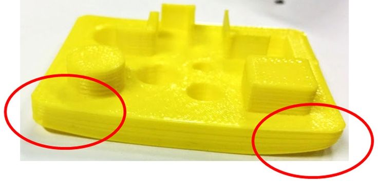 Many 3D printer models have a built-in enclosed chamber, but those that don’t can still benefit from a DIY enclosure. Other ways to improve temperature consistency in your 3D printer are to adjust cooling fan speed settings (especially for the first layers of a print) and keeping your room temperature as ambient as possible (i.e. keeping cold air out by closing windows).
Brim or Raft
Brims and rafts are tried and true techniques for boosting bed adhesion, especially for ABS and other high-temperature filaments. These 3D print features are added in slicer software right before printing and have several functions.
Specifically, a brim is a 3D printed border that connects to and goes around the edges of a 3D printed part. Brims are typically a few millimeters wide and consist only of 1-2 layers. They increase the footprint of the 3D printed part and anchor its edges to the build platform. A raft is similar, only it is also printed under the 3D printed part, acting as a base for it.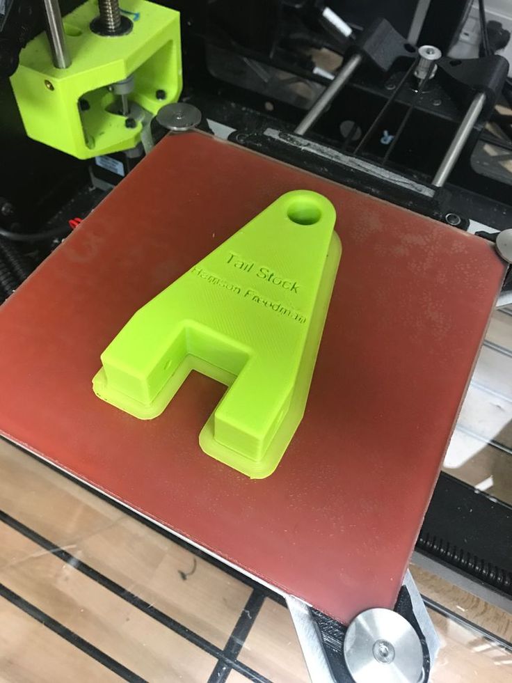
Brims and rafts are especially beneficial for 3D printed parts with unbalanced geometries or small footprints, as they can stabilize the print and secure it to the build surface. Both brims and rafts must be removed after printing, either by hand (by peeling them off) or using a tool. Printed parts with brims or rafts may require additional post-processing to achieve a smooth first layer.
3D printed brims can help to anchor the printed part down to the build platform.
Slicer settings
The risk of warping can also be reduced substantially by implementing the right print settings for the first layers of the printed object. Most slicer software programs allow you to adjust the print speed and layer height specifically for the first layer. A slower print speed for the first printed layer of a build will help to ensure that the filament sticks to where it has been deposited and is not pulled by the nozzle as it moves. Choosing a slightly thicker layer height for the first layer can also improve bed adhesion and help reduce any leveling inconsistencies.
Another print setting that can influence warping is fan speed. Fans are built into some FDM 3D printers and ensure the build space does not get too hot. By tweaking fan speeds you can maintain closer control over print cooling. For example, fans can be programmed to turn on only after the first few layers of a print have been deposited. This helps the first layers cool slowly and evenly on the print bed.
Conclusion
3D print warping is a frustrating problem most makers will encounter at some point or another. By following the tips and methods laid out in this article, however, you can ensure good bed adhesion, consistent printing temperatures, and ultimately reduce warping and improve print quality overall.
References
[1] TapeManBlue, 2022. “The Complete Guide to Blue Tape for 3D Printing”. [Internet]
https://tapemanblue.com/blogs/tips-tricks/blue-tape-for-3d-printing [Accessed March 31, 2022].
[2] Ultimaker, November 10, 2020. “Build plate adhesion: How to get your print to stick to the build plate”. [Internet] https://support.ultimaker.com/hc/en-us/articles/360012015680 [Accessed March 30, 2022].
[3] Simplify3D, 2022. “Warping”. [Internet] https://www.simplify3d.com/support/print-quality-troubleshooting/not-sticking-to-the-bed/ [Accessed March 30, 2022].
Why 3D Printed Parts Warp and How to…
Designing for 3D Printing (DF3DP) is a blog series devoted to 3D printing tips and tricks to follow when using any 3D printer that will guide you through reducing costs, print time, and material while also showing you how to get your parts the way you want them first try.
If you’ve ever used an FFF 3D printer, you’ve probably experienced part warping for large, long, or oddly shaped parts. Usually this means you either have to do some post processing to make them flat again, or you’ll have to just accept dealing with an uneven bottom surface that you probably assumed would print flat.
3D printed part warping is a tricky problem to get around; just because a 3D printer is reliable, doesn’t mean it won’t have this problem. 3D printed parts warp because of thermal deformation. When plastics heat up, they expand. When they cool, they shrink. Because FFF 3D printing almost always involves thermoplastics, this happens with almost every FFF 3D printer. On the printer side, there are two things that fix warping: a heated build plate, or a heated enclosure. These two solutions keep the part at temperature, so it doesn’t cool, therefore, no warping. Simple! Other 3D printers will have an enclosure that keeps the heat in, and/or an adhesive to apply to the build plate (like ours) which usually ends up helping reduce warping as well. Additionally, letting the part cool to room temperature before removing it will reduce warping because the part cools while still adhered to the build plate.
But really, it’s less about the system and more about the part design. The notion that “3D printers can print anything” is untrue (more on this in a future blog post!), because 3D printers often have as many limitations and design guidelines as other manufacturing methods.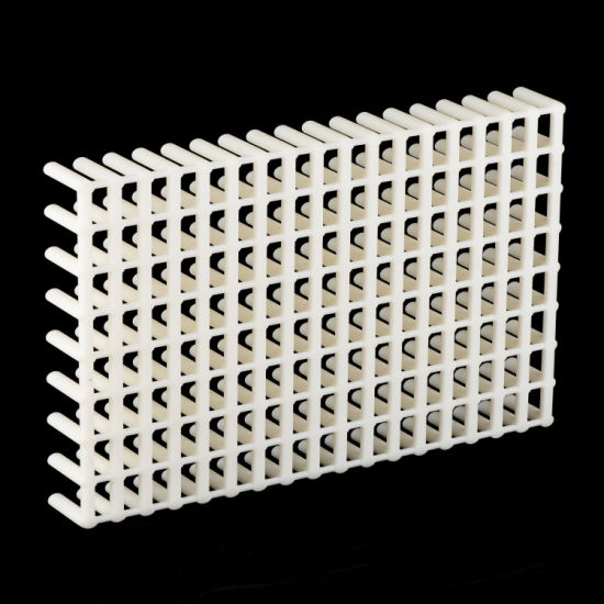 To name an example, the smallest feature size an FFF 3D printer can create is dependent upon nozzle diameter and gantry accuracy. Anyways, many parts warp simply because of the material limitations of FFF 3D printers combined with part design not optimized for 3D printing.
I’ve designed a simple triangular prism truncated on one edge that is fairly prone to warping (for reasons you’ll find out about soon). Here’s the 3D model in Eiger:
A warp test piece. The long, thin geometries and sloped surfaces make it prone to warping.
And here’s a shot of the part warping after it came off the build plate. To demonstrate warping, I’ve clamped down the piece on one side of the table and observed the deflection on the other side:
As you can see, this 3D printed part warps on either side, making the bottom surface uneven.
These five tips serve as 3D printing design guidelines so that you can reduce warping on 3D printed parts during your design process. I hope they help!
1.
 Fillet Edges and Design with Round, Natural Shapes in Mind.
When 3D printed parts warp, it’s because of a thermal moment formed around the edge of a part. This thermal moment is caused because when FFF printers lay down filament, they are heating the plastic until it is semi-fluidic and then cooling it down after it is extruded. When most materials cool, they want to shrink. In the case of FFF 3D printers, this means that each “line” of material will want to contract lengthwise. Usually, this is not enough to break adhesion with the build plate, but this force builds up as more layers are added, making the part warp. This is especially common with long, thin parts, like the test piece I’m using in this post, because of the lengthwise contraction.
When more corners are added to a line segment that wants to shrink, the corners will peel up because of the build up of stress at that location, as shown in the diagram below:
Warping occurs at corners because the forces from each edge add up.
Sharp corners create stress concentrations, so corners are the most common geometries that induce warping. Adding a fillet to these corners reduces the stress concentrations because the sharp corner gets rounded off, and the stress gets distributed. In general, creating cross sections that are more round in shape when contacting the build plate will reduce warping – when engineers design parts they usually end up being rectangular in shape; that is commonly what is easiest to machine. But designing from the start with more round, natural shapes and surfaces will reduce warping because it distributes the stress build up. Below, I have edited the test piece by adding a fillet to the corners.
Rounding off edges normal to the build plate reduces stress concentrations caused by warping.
Even with this simple change, fillets on the edges reduced warping significantly.
Adding fillets reduces the stress that builds up on the corners, thus reducing the force caused by thermal deformation.
Another quick tip with fillets – adding a fillet to the bottom edge of your part will allow you to remove it from the build plate more easily – it gives a good lip to get a scraper under!
2. Print parts with the largest face on the bottom.
As layers stack on top of one another, these forces multiply. If the layer above the one that was just placed down is slightly larger, then there is more added material that wants to shrink, so the force increases even further. This means the worst shapes to 3D print are shapes with larger cross sections as you go up, and shapes with sharp corners after long, straight segments, just like our warp test!
Parts don’t always warp just on their bottom layer, though – warping can occur wherever these geometry conditions exist. Frequently long, extruded overhangs end up curling up for the same reasons, even if they are supported, as shown by this thin angled overhang below:
Even though this part didn’t warp at the bottom, the long, stacked profiles caused the part to curl up at the overhang and fail.
So when 3D printing parts, it’s important to try and get the largest face on the bottom because parts tend to warp as the cross section gets larger on top of stacked layers. Additionally, the more surface area you have contacting the build plate, the better, because a larger surface area will hold better. I printed the truncated prism upside-down, in the orientation shown below:
The orientation of a 3D printed part is really important – simply designing with print orientation in mind can solve a lot of problems.
And as you may expect, no warping:
Neither side of the part is warped, because the way the layers stacked reduced the forces on the part.
Although this is a simple example, and with a part like this it may be clear that it should be printed with the largest face down, in some scenarios it is not quite as obvious, so remember to consider build orientation when designing the part.
3. Add a Brim
A brim can be added to parts using the “brim” tool, which essentially adds some extra contact area to the build plate surrounding your part.
Select “Use Brim” under “Advanced Settings” to add a brim to your part.
This reduces warping or curling for two reasons. One, the part has an “extended” bottom surface, meaning that the contact with the build plate is larger than it would be normally. Two, any warping that occurs transfers to the brim, which will take the worst of it. The brim additionally gives a better surface for support structures to adhere to. Our support structures are long, thin lines, which, as I explained above, really want to contract. If you have a lot of support material beneath your part, a brim will provide a good surface for the support structures to stick to. The supports won’t curl as much because they are sticking to the brim – a flat, large area surface sticking to the build plate. Below is a test of the part with a brim:
Adding a brim reduces 3D printed part warping by increasing contact area with the build plate.4. Make Your Own Brim
Sometimes, due to odd build plate contact point geometries, parts will still warp just because the brim may not be large enough or curved enough. In these unique cases, it may be necessary to CAD your own brim. What is suggested in these scenarios is to add thin, round “dots” to all of the corners of your part, which will provide more surface area contact with the build plate at key points where warping occurs.
Sometimes, designing your own brim is necessary to reducing 3D printed part warping.
My own designed brims eliminate warping just as well as our pre-fab brim, and may come in handy for more complicated parts:
The “dots” on each side provide more contact area at the corners for the part to adhere to, and can be clipped off later.5. Add Composite Fiber to Your Part
One of the unique capabilities of the Mark Two is its ability to lay fiber inside components to make stiffer and stronger 3D printed parts. Because of the composite material capabilities of Markforged 3D printers, to reduce warping in a part you can add fiber to the bottom few layers to increase its stiffness.
A view of the warping test piece in Eiger, with fibers on the top and bottom.
This essentially forces the bottom layers to be flat, making it almost impossible for them to warp. If you’re doing this, however, remember to balance the composite by creating a sandwich of fiber at a top and bottom surface of your part to optimize for torsional strength, as described in this blog post. As you can see, With no design alterations to the original part, the test warp piece remains flat:
Adding fiber will force the layers to remain flat because of the increased stiffness.Extra Tip: Print in Onyx!
As described in tip #5, minimizing warping can be tackled from a materials standpoint with our Continuous Fiber Fabrication (CFF) method. But some of our other materials come in handy when solving this problem as well. Onyx, our micro-carbon reinforced filament, does not deform nearly as much under heat. This means that it warps much less than our standard nylon, and creates much more dimensionally stable parts. You can read more about the dimensional stability of Onyx here. With no fiber reinforcement, the Onyx filament remains stable:
Onyx is a more dimensionally stable material, and its thermal properties mean it warps much less.
I hope this post helped you understand why 3D printed parts warp and how to improve your designs to eliminate warping! If you want to try out your own experiments for reducing warping on 3D printed parts, give it a shot with the stl file and mfp file yourself! If you have any questions, suggestions, or ideas for future blog posts please let us know at [email protected].
How to avoid deformation of models when 3D printing
There is nothing “better” than walking away from the printer for a couple of hours and taking a nap, and returning to find this:
Vermicelli. Plastic
Sound familiar? Yes, these are the same “angel hair”, “spaghetti” or “vermicelli” obtained by tearing the model off the desktop. The cause of such a disaster is often the deformation of the layers. Twisting the edges of the model up causes the extruder to catch on the model and simply break or tear it off the platform. Then begins the artistic filling of the environment with plastic thread in the artistic style of Jackson Pollock.
Left: No. 5, 1948. Author: Jackson Pollock. Fiberboard, oil. Price: $140 million
Right: Angel hair, 2013. Author: Ravix. Prusa Mendel printer, ABS plastic. Price: $0
But the charms of deformation don't stop there. What is the easiest way to quarrel two "makers"? Correct answer: ask them which is better - PLA (polylactide) or ABS (acrylonitrile butadiene styrene). ABS - a thing, of course, tempting. This plastic is strong, durable and inexpensive. Polylactide, in general, is also relatively inexpensive, but relatively soft and biodegradable - with all the ensuing consequences. So why are popular devices like the Makerbot Replicator built to print with only polylactide? The environmental friendliness of PLA is a secondary reason, rather a bonus.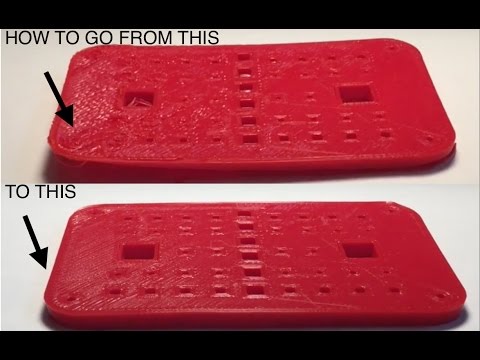 And the main reason is the low glass transition temperature and minimal shrinkage. It does not require heating to ultra-high temperatures for melting, and when cooled, although it shrinks, losing volume, but not much. In other words, printing with polylactide is easier. But ABS “shrinks” quite noticeably, losing up to 8% of its volume. If you do not control the temperature regime, then you can get curvature and even cracks.
In our article, we propose to consider methods for eliminating deformation.
- 1 Use heated platform
- 2 Choose the right adhesion
- 3 Cleanliness is key to good printing
- 4 Height calibration
- 5 You drive more quietly - you will continue
- 6 Don't catch cold on your model
- 7 Turn down the heat
- 8 Reduce the density of model
- 9 Print with liner
- 10 Lugs
- 11 Thresholds
- 12 Thermowalls
Use Heated Bed
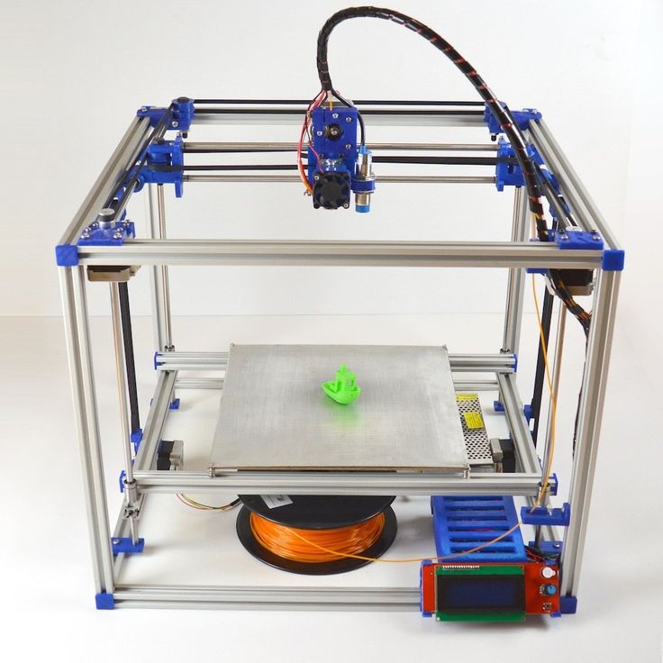
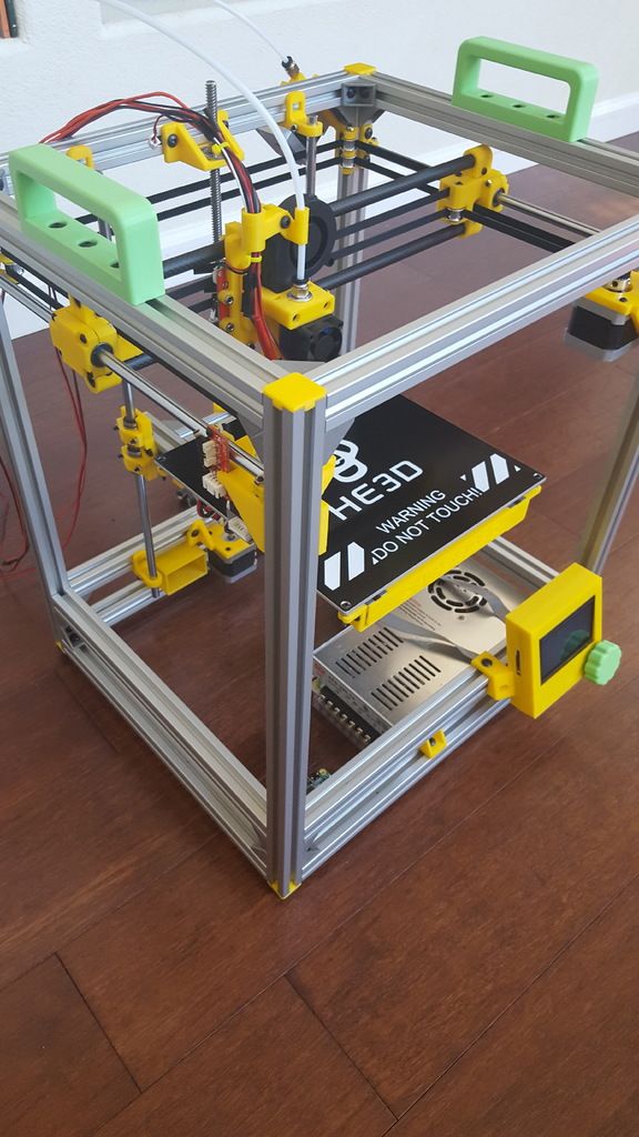
Heated Build Bed
This option is offered with many modern 3D printers, and in the case of the RepRap, you can modify it yourself. Let the heating add to the cost of the printer, but it's worth it. Heating the model from below allows you to slow down and even out the cooling process. If small PLA models can be printed without heating, then when printing large objects, a heating element is no longer necessary, since even a slight shrinkage of PLA has a cumulative effect with increasing model dimensions. When printing with ABS plastic, heating is simply necessary, otherwise the rapid shrinkage of the lower layers will lead to deformation of the upper, still hot parts of the model. It is worth paying attention to the uniformity of the platform heating. If the heating is not uniform, then the very first layers, cooling unevenly, can “twist”. Often the glue or tape used to hold the model in place won't even help. The edges will rise, the extruder will hook on the applied layers, and then - "vermicelli".
Choose the Right Adhesion
Kapton is a Great Platform Coating
If the plastic won't adhere to the platform, you're in trouble. Which one is the best - there is no consensus. There are tables made of aluminum, glass (even basalt), steel, titanium. Seasoned RepRapers pray for Kapton, a polyimide film applied to the surface of the platform. By the way, the film can be processed with a fine-grained emery cloth - a rough surface will contribute to the "seizure" with the plastic. Some users spray the surface of the platform with a spray adhesive containing acetone (to set the ABS), or even hairspray!
Cleanliness is the key to good printing
If the build platform is covered in dust, plastic will stick to the dust. How this will affect the adhesion of the model to the platform itself hardly needs to be explained. If you are printing with ABS, you can wipe the platform with acetone to dissolve the small pieces left from previous models. Acetone has no effect on polylactide, but you can try Limonene. By the way, the thread should also be kept clean, because the accumulation of dust in the extruder is fraught with all sorts of interesting, but unpleasant consequences.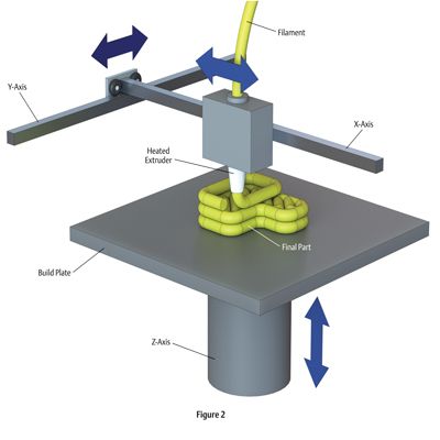 One simple method to clean the filament (if it's already dusty) is to use a foam filter before feeding it into the extruder.
Height calibration
Trying to print a cube with too much initial distance between nozzle and bed
A correctly applied first layer is the cornerstone of successful printing. If the head sits too high above the platform when applying the first coat, the adhesion may be too weak. This problem is solved experimentally: if your model breaks off the platform, try lowering the initial head height in small steps. If the platform is heated, then it makes sense to carry out the calibration in a heated state, because the deformation of the platform during heating can make the “cold” calibration inaccurate.
Slower ride - farther you will be
Reducing print speed can reduce model deformation
Yes, unfortunately, 3D printing even small objects takes a lot of time.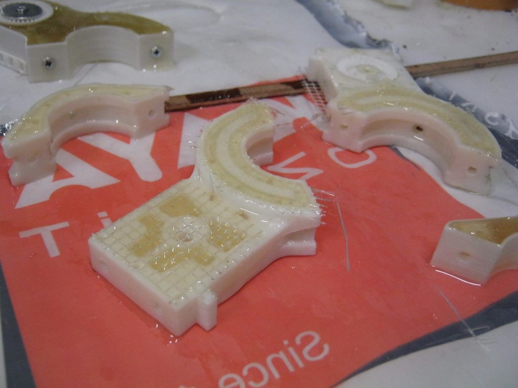 But in order to increase adhesion to the platform and give the layers extra time to cool evenly, it may be necessary to slow down the printing process. This is especially important when working with PLA, because the polylactide takes a long time to cool down, and the lower layers can undergo deformation under the pressure of the upper layers if they do not have time to pass the glass transition point.
Don't catch cold on your model
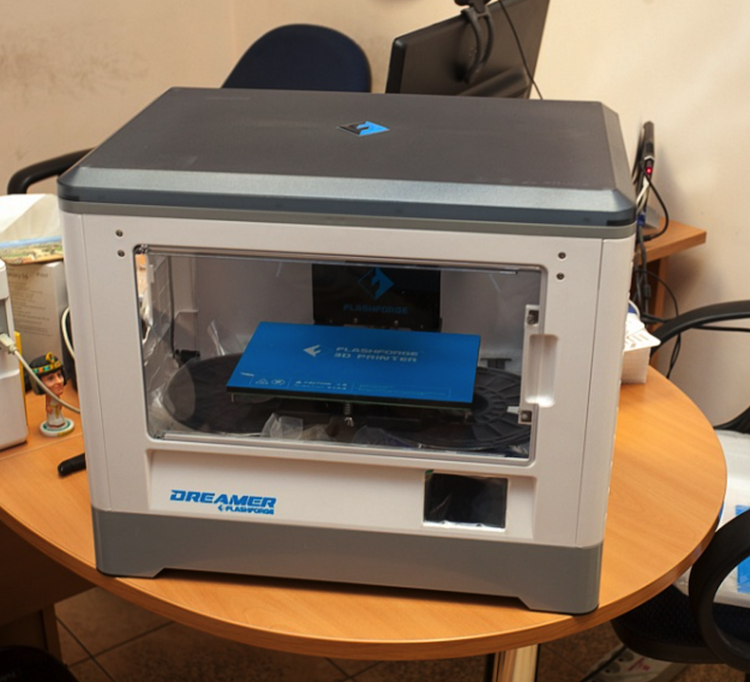
Maker Case - a cabinet for 3D printers that prevents drafts
Drafts can have negative consequences not only for real people, but also for plastic ones. A banal draft can lead to uneven cooling of the model - hypothermia on one side, followed by one-sided shrinkage and lopsidedness. No wonder many manufacturers prefer to make closed cases for their printers. In addition, the tightly closed housing helps maintain a high background temperature in the working chamber, which is good when working with ABS plastic. But when printing PLA, you may have to remove one of the panels or open the door (depending on how the case is arranged) to help cool the model faster. Many manufacturers install additional fans on their extruders to blow off the fresh layers of polylactide (we counted three on the PrintBox3D One!). Although, in general, this is a sound idea, it often has the opposite effect, since only one side of the model is blown. In the case of PrintBox3D One, the calculation was made to quickly cool fresh layers - before subsequent layers become a barrier to airflow. And Picaso Builder uses a tricky system of channels built into the extruder to evenly blow the model from above.
Turn down the heat
Not yours. This refers to the temperature of the extruder. The ideal option is to heat the extruder to a temperature slightly above the glass transition temperature of the plastic, so long as the extrusion proceeds normally and the layers “seize” among themselves. After all, the stronger the plastic is heated, the longer it will cool down, and the more noticeable the shrinkage will be. But keep in mind that such experiments can bring additional stress on the extruder mechanism, up to and including damage to it. Yes, the nozzle can get clogged. Be careful.
Decrease the density of the model
Various degrees of filling
The model can be homogeneous (solid piece of plastic), hollow (walls on the outside, absolutely nothing inside), or lightweight (seemingly solid, but inside filled with plastic mesh or honeycombs) . The last option has a lot of advantages. This includes savings in materials compared to solid models, good strength compared to brittle hollow models, and, finally, a reduced likelihood of deformation. The logic is quite simple: the larger the surface of the layer in contact (i.e., sticking together) with the platform, and the smaller the volume of plastic in the following layers, the less likely the lower layer is to twist when the upper layers shrink. Add the already described substrates here, and the chances of successful printing increase many times over.
Print with a backing
Printing a wheel on a backing
A backing or "raft" is the base of the model, made in the form of a grid. Due to the high porosity, such structures cool quickly and evenly, and then serve as a reliable basis for the present model. The larger and thicker the substrate, the stronger and more reliable it is. Here you already have to find the perfect balance between functionality and material consumption. Many digital modeling programs (such as Skeinforge or ReplicatorG) have built-in underlays.
Lugs
Model with lugs
The problem with underlays is that they can seriously degrade the quality of the bottom layer of the model. After all, all this extra plastic will have to be removed, right? Alternatively, you can print the extensions of the bottom layer (the so-called "lugs") in the most vulnerable places for twisting - for example, in the corners. The lugs will help hold the edges in place until the bottom of the model hardens. After printing, they will be much easier to remove than the backing. The disadvantage of this technique is the need for an additional work surface.
Thresholds
Threshold Model
Essentially it is a combination of lining and lugs. The oversized lining is built on with additional objects (“thresholds” or “visors”) whose sole purpose is to hold the lining in place. The most effective method of preventing deformation of the lower layers, but also the most costly in terms of materials. The advantage is the fact that the “thresholds” themselves do not touch the model, and therefore, at the end of printing, only the substrate itself will have to be cleaned from the model.
Thermal walls
A kind of draft control. The idea is based on the construction of thin walls around the model, which keep warm air inside and contribute to a more uniform cooling of the model.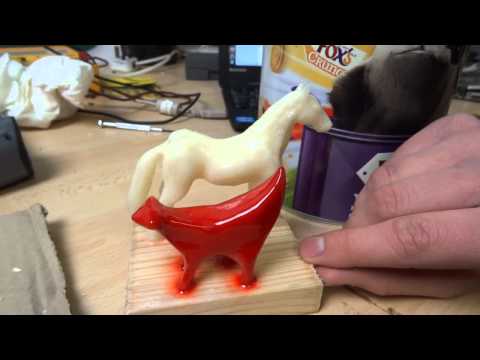 In fact, this is an alternative to the closed printer case. The walls themselves can be deformed, but since they are not part of the model, this is not a problem. The downside is the additional consumption of materials.
If you have your own tricks, write to us at [email protected]
Go to the main page of the Encyclopedia of 3D Printing
Problems, defects, 3D printing errors and solutions
Often during the operation of a 3D printer, problems may arise due to which defects appear on the finished model. Or instead of a neat product, plastic noodles suddenly appear on the table.
In fact, the causes of defects can be conditionally divided into 2 types - these are physical and software.
Physical ones are those that arise due to problems with the mechanics or any other causes that can be eliminated physically. These include problems with printer mechanisms (belt tension, backlash), clogged or deformed nozzle, incorrect table geometry, etc.
Software - these are defects that occur due to incorrect slicer settings or, less often, errors in the printer firmware. For example, incorrectly selected print speed, retract settings, incorrectly selected temperature for plastic, etc.
Very rarely, the problem may lie in the wrong or “flying” printer firmware (although usually the printer simply will not start then), overheating of some boards during printing, etc. These are rather special cases, so we will not consider them.
Model peels off or does not stick to platen
This is the most common 3D printing problem. Every 3D printer has had a case when the first layer treacherously rolls, clinging to the extruder, or the most offensive - when it tears off a partially printed model from the table. The first layer must stick tightly otherwise nothing will be printed.
Gap between table and nozzle too large
This is the most common reason. You just need to set the correct gap between the table and the nozzle.
Modern printers often use an auto-calibration (auto-leveling) table system or an auxiliary table leveling program. To calibrate such printers, use the instructions. If there is no manual, it can be downloaded from the manufacturer's website.
If you have a simple printer without auto-calibration, a self-assembly or KIT kit, use a probe or a piece of paper folded in half to calibrate. The probe should be slightly pressed against the table by the nozzle. Before calibration, the table and extruder must be heated. Align the table surface over each adjustment screw (there may be 3 or 4) in turn, and only then check the center point.
If you're having trouble getting your table surface perfectly level, try raft printing. Raft is a thick substrate in several layers that is printed under the model. It will help smooth out the slight curvature of the table.
A small cheat sheet to determine the correct gap on the first layer
Plastic with poor adhesion
Some types of plastic, due to various reasons, such as large shrinkage, do not adhere well to the surface of the printing platform. In this case, try using stickers or special 3D adhesives to improve adhesion between the table and the first layer of plastic.
In the early days of 3D printing, there were experiments with different homemade 3D adhesive recipes. ABS diluted in acetone, BF glue, sugar syrup and even beer. Some experiments have been successful. Until now, some enthusiasts use some types of hairspray or glue sticks as 3D glue. But still they are inferior in their properties to industrial 3D adhesives.
Some types of high temperature plastics with a high percentage of shrinkage (ABS, Nylon, etc.) may peel off the table during printing. This is due to uneven cooling and “compression” of the model (the lower layers have already cooled down, but the upper ones have not yet). For such plastics, it is imperative to use a 3D printer with a heated table and a closed case.
Plastic temperature too low
The hotter the plastic is when it exits the nozzle, the better it will adhere to the print bed. It is better to print the first 5-10 layers at a higher temperature (+ 5-10 degrees) and turn off the blower fan.
Wrong first layer settings (speed and thickness)
A thicker layer sticks easier, so the standard first layer is 0.3mm thick. With an increase in print speed, the heating block may simply not have time to heat the plastic to the desired temperature and it will stick to the table worse. Before printing, check the speed and thickness settings of the first layer in the slicer.
A lot depends on how the 3D printer prints the first layer. Try to control the printing of the first layer and only then leave the printer to work alone.
Plastic does not choke from nozzle
The printer has already begun to print, but the print table remains empty. Or part of the model did not print.
Clogged nozzle
In 3D printing, a nozzle is a consumable. The nozzles are clogged or worn out (frequency depends on the type of plastic). The simplest thing is to replace the nozzle. But if there was no spare at hand, you can try to clean the old one. To do this, there is a whole set of thin needles. Or you can heat a clogged nozzle above the melting point of the plastic and “burn out” the blockage. But later it is still better to replace the nozzle.
Low temperature nozzle
You need to increase the temperature of the extruder in the slicer settings or check the thermistor and heating block. Sometimes the thermistor may not read the temperature correctly due to a malfunction or incorrect 3D printer firmware settings.
If the problem occurs after replacing the thermistor - contact the manufacturer or read articles about PID tuning.
Empty extruder
As the extruder heats up, plastic begins to ooze out of the nozzle. Because of this, the extruder may start printing half empty. Because of this, part of the first layer is not printed. You can push the plastic manually by simply pushing the bar into the nozzle. Or solve this problem programmatically - in the slicer, add a contour print around the model (one line).
Some manufacturers and 3D enthusiasts add a line print on the edge of the table at the beginning of each GCode. This is done so that there is plastic in the nozzle by the time the model is printed.
Feeder does not push through plastic
The plastic pushes the feed mechanism to the extruder - a motor with a special pulley put on the shaft. If for some reason the plastic is not pushed through (nozzle clogged, extruder temperature low, etc.), then the pulley “gnaws” through the bar. You need to push the plastic bar with your hands or cut off the damaged piece.
Elephant foot
The first layers of the model are wider and protrude beyond the boundaries of the model. This is due to the fact that the upper layers put pressure on the first ones that have not yet cooled down and flatten them.
Table high temperature
Due to the too high temperature of the table, the lower layers remain soft for a long time. Try lowering the table temperature. It is better to reduce gradually (in increments of 5 degrees). You can try to turn on the blower when printing the first layers.
Small gap between nozzle and platen
If, when printing the first layer, the nozzle is too close to the table, then excess plastic will be forced out. After a few coats, this will not be as noticeable, but can lead to the effect of an “elephant's foot”.
Plastic re-extrusion
When too much material is squeezed out of the nozzle, the walls of the model are not smooth, but bumpy, with sagging.
The solution is software - in the settings of the slicer, you need to set the material feed rate (fluidity) to a lower value. The average value is 95-98%.
It is worth checking the diameter of the rod. If its size is greater than 1.75, then the plastic will be squeezed out more than necessary.
Plastic underextrusion
The plastic is squeezed out too little, because of this, gaps may appear between the layer. The finished model will be fragile and fragile.
Wrong thread diameter
Check the filament diameter in the slicer settings. Sometimes, instead of the popular 1.75, the default is 2.85.
Incorrect feed factor settings
Check the fluidity settings in the slicer. The average should be 95-98%.
Clogged nozzle
Something could get into the nozzle and partially block the exit of the plastic. Visually, the plastic will choke from the nozzle, but in a smaller amount than necessary for printing.
Hairiness or cobwebs on finished model
Thin threads of plastic protrude from the outer wall of the model (most often on one side).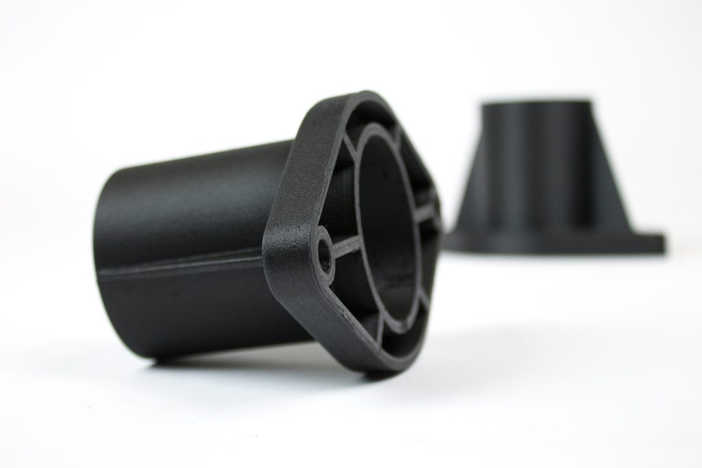 The defect appears due to the flow of plastic from the nozzle during idle movement.
Insufficient retract
A retract is a slight pull of a plastic filament from an extruder. Due to the retract when the extruder is idle (from layer to layer or from model to model), heated plastic does not drip from the nozzle. For some flowable plastics (eg PETG) the speed and amount of retraction must be increased.
"Hairiness" can be easily removed by grinding or cutting off the threads with a sharp scalpel.
High temperature extruder
The higher the extruder temperature, the more liquid the plastic becomes. It is important to find a balance so that the plastic is not too liquid and sticks well in layers.
In the selection of the optimal extruder temperature, a test model - a tower - helps a lot. It clearly shows how plastic behaves when printed at different temperatures.
.
Temperature test
Top "perforated" or uneven
The top of the model is bumpy or with holes. The problem may arise if the top of the model is flat. For example, like a cube.
Insufficient airflow
When printing the top plane (cover), the plastic does not have time to cool down and remains too liquid. Because of this, the threads are torn and holes are formed. Increase the fan speed on the last layers.
Few top layers
The top of the print may be too thin and deform as a result. Check slicer settings. The number of upper layers is not recommended to be set less than 6.
Fill percentage low
If the infill percentage is too low, then the top layer will simply have nothing to rely on. Increase the fill percentage in the slicer settings.
Model deformation
Some parts of the model seem to have melted in some places or on one side. The problem most often occurs when printing with PLA plastic. The defect appears due to the fact that the plastic does not have time to cool and deforms.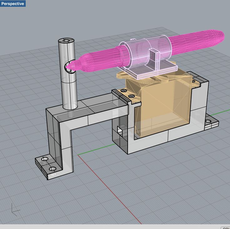
Insufficient airflow model
Turn the fans on to maximum. If their power is not enough (in some printers, the fan is located only on one side), you can put a regular desktop fan and direct it to the 3D printer table.
Small model
Small models are difficult to blow well. Try to print small items alongside larger ones, or place several identical models in different corners of the table. So the plastic will have more time to cool.
Layer offset
Layers shift along the x or y axis during printing.
Print head jam
Turn off the printer and try to move the extruder along the x and y axes with your hands. The extruder must move freely. If there are jams, check the mechanics of the printer. Bearing wear or the curvature of the shafts may be to blame.
Electronics overheating
Sometimes electronics problems can be to blame for misaligned layers.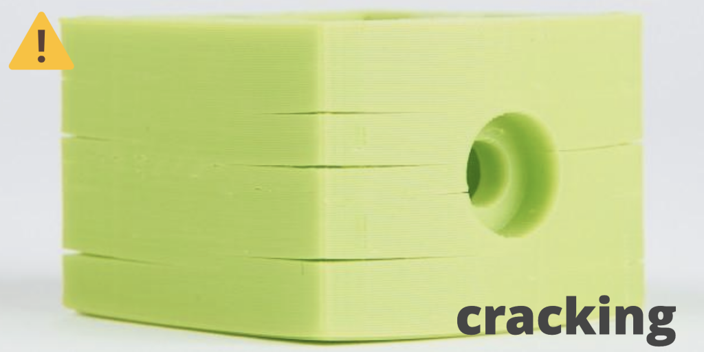 The most common cause is overheating of the drivers or too low current exposed to them.
Table top is loose
This is most often seen in 3D printers with glass. During printing, the nozzle may hit the model and move the glass slightly. Before printing, check if the glass or other printing surface is well fixed on the heating table.
Skip layers
Small holes are visible on the print, or the shell of the model is not continuous.
Teflon tube deformed
There are 2 types of thermal barriers - all-metal and with a Teflon tube. If overheated, the Teflon tube may deform. Plastic will pass through it, but in a smaller amount.
Low extruder temperature or high print speed
If the extruder is not heated enough, then the plastic will not be liquid enough and simply will not have time to be forced through the nozzle. The higher the print speed, the higher the extruder temperature should be.
Sometimes the outer walls print well, but the infill is “torn”. In this case, slow down the infill print speed in the slicer.
Model bundle
Cracks form on the surface of the printout during or after printing. Cracks can be large or very small. Most often, this problem occurs with plastics with a high percentage of shrinkage - ABS or Nylon.
Sudden temperature difference (if model delaminates during printing)
With a sharp temperature difference (for example, a draft), part of the model cools down faster. This leads to uneven shrinkage and incorrect distribution of internal stress. For plastics with low shrinkage, this is not critical. But if the shrinkage percentage is more than a few percent, the model may burst in layers.
For printing with such plastics, it is recommended to use a printer with a closed housing. If this is not possible, try to avoid drafts and sudden temperature changes in the room where the 3D printer prints as much as possible.
Print temperature
Due to too low printing temperatures, the layers may not “stick” well to each other. Raise the print temperature in the slicer settings.
Hardening (if the model cracks after printing)
Sometimes cracks appear on the model a few days after printing. This is due to uneven distribution of internal stress after cooling. You can try to “harden” the finished product.
For hardening, the model is placed, for example, in an oven, and heated to the softening temperature of the plastic. After that, the heating is turned off and the oven is left to cool slowly with the model inside. Due to this, the stress inside the print is distributed more evenly. But accuracy is very important in this method - if you make a little mistake with the temperature, the finished product can “float”.
Ringing
In places where the extruder changed direction, ripples are visible. Most often it looks like a shadow around the “sharp” protruding elements of the model.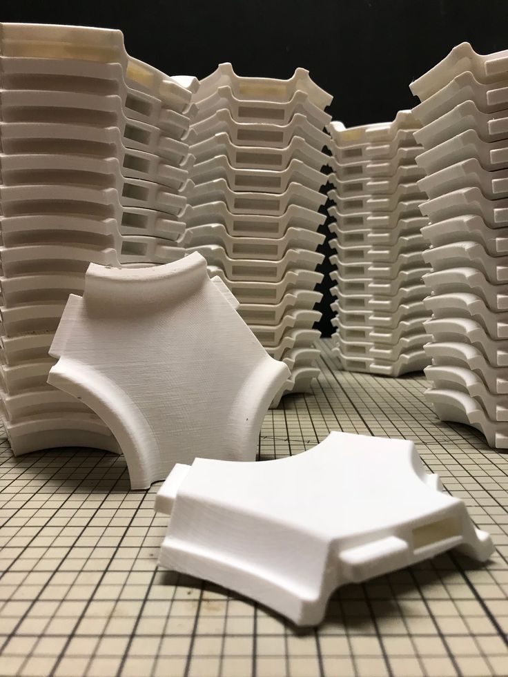
Mechanical problems
Sometimes the problem occurs due to extruder play. Check if the extruder mount to the rails is loose. Be sure to check the tension of all belts.
High print speed or high accelerations
Moving the extruder too fast can cause vibrations that cause ripples on the wall of the model. The lighter the weight of the extruder, the less noticeable the ripples will be. To get rid of ringing, simply reduce the print speed in the slicer settings.
Slots for thin-walled models (not solid shell)
The thin wall of the model is not solid, but consists of two thin walls with a narrow gap between them. This problem is often faced by fans of printing "cutting" for baking.
Left model with wall defect, right without
Wall thickness and nozzle diameter mismatch
If the wall thickness is 1 mm, and the nozzle diameter is 0.4, it turns out that for a solid wall, 2 nozzle passes are few, and 3 are already many.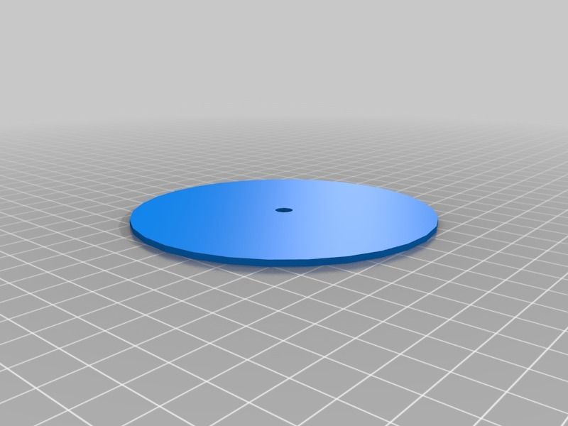 The result will depend on the slicer algorithm, but most often you will get 2 walls with a thin slot in the middle (the slicer cannot change the wall thickness). The solution to the problem may be a slight refinement of the 3D model or the use of a different slicer.
Algorithms for calculating 3D models are constantly being improved and refined, and now this problem is less common.
When modeling, take into account not only the thickness of the nozzle, but also the percentage of “overlapping” of lines on each other. If you have a nozzle with a diameter of 0.4 - make the wall in your model not 0.8, but 0.7 - 0.75.
Wrong model geometry
When instead of a circle you get an oval, and instead of a square you get a semblance of a rhombus.
The main reason is malfunctions in the mechanics of the printer. Be sure to check:
Belts
Check belt tension in x and y.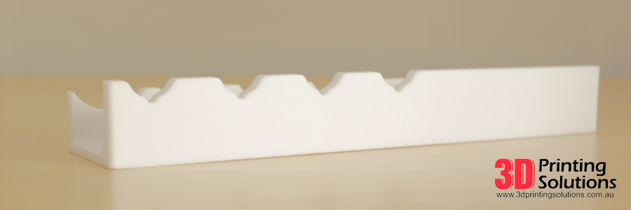 Belts stretch over time and may need to be tightened or replaced. Each 3D printer has its own way of tightening the belt. If the belts are slightly stretched, you can tighten them with the help of a "spring".
Loose pulleys, etc.
Check if all bolts and nuts are tight. Are there backlashes. Pay special attention to tightening the pulleys located on the motors along the x and y axes.
Sagging of some parts of the model
Some parts are not printed, broken, or instead of a neat surface, a swollen plastic snot is obtained.
No support for overhangs
A 3D printer cannot print in the air, so if there are overhanging elements in the model, you need to set supports - supports. The slicer can set the necessary support itself, you need to check the appropriate box in the settings.
When printing with soluble support, you can set the gap between the model and support - 0.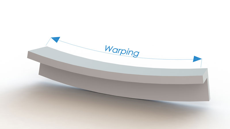 This will make the surface smoother. If the support material and the model are the same, you need to add a small gap. Otherwise, it will be difficult to separate the support from the model.
Split model
Sometimes the supports can take more plastic than the model. In this case, to save material and time, it will be more convenient to cut the model. If you have more than one 3D printer, then the model will print several times faster.
When cutting the model, you can leave grooves or mortgages so that the pieces of the model are connected without displacement.
Totals
In this article, we talked about the most popular 3D printing defects and how to solve them. Don't be intimidated by such a long list. Some problems are rare and you are unlikely to encounter them.
There is a list of problems that arise due to the design features of a 3D printer, so try to choose a printer that suits your needs. To do this, you need to understand what products and what material you need.