3D scanner germany
Gold Star 3D Scanner - German Group
Gold Star 3D Scanner
9,500 U.S
Change Currency:
USD U.SKWD K.DSAR S.AEGP E.GEUR E.UGold Star 3D Scanner from Mega Detection offers the prospector of ancient antiquities and the seeker for buried treasures at great depths, the best integrated and comprehensive solution in terms of the multiplicity of search technologies available in the device, as well as practical applications and uses in the field of metal detection
0 out of 5
( There are no reviews yet. )
FREE SHIPPING
100% MONEY
BACK GUARANTEE
ONLINE
SUPPORT 24/7
Gold Star 3D Scanner from Mega Detection offers the prospector of ancient antiquities and the seeker for buried treasures at great depths, the best integrated and comprehensive solution in terms of the multiplicity of search technologies available in the device, as well as practical applications and uses in the field of metal detection
Brand: Mega en
Contact With Relevant Department
Add to wishlist
- Description
- Parts & Contents
- Videos
- SEARCH SYSTEMS
- Additional information
- Reviews (0)
Description
Details
Gold Star 3D Scanner from Mega Detection offers the prospector of ancient antiquities and the seeker for buried treasures at great depths, the best integrated and comprehensive solution in terms of the multiplicity of search technologies available in the device, as well as practical applications and uses in the field of metal detection.
Device Features
- Gold Star 3D Scanner is An integrated multi-functional device that combines a professional metal detector and a 3D ground scanner with high-quality performance in all-terrain and accurate, reliable results.
- Modern and practical design that combines lightweight and aesthetics of look and suitability for long real-life use in the search fields and made of high-quality materials, which provides the user with a comfortable user experience.
- 8 different search systems that include the latest developments in the field of metal detection technologies with wide options to adjust search settings and options to suit various factors such as the ground soil type, the terrain, the purpose of the search, and the type and metal of buried targets.
- A completely new patented 3D ground scanning technology that includes advanced search tools that guarantee more accurate results through larger coverage and visual representation of scanning data on the device’s screen or via a tablet computer.

- An advanced 3D analyzing app that can be downloaded on any tablet or smartphone running Android, provides the prospector with great capabilities to analyze the results of the ground scan visually through integrated tools through which can know the type of metal – the exact location or position – the accurate depth of potential targets and target metal type.
- A new and improved technology in long-range metal detection technology that includes performance improvements, a wider scanning field, and more depths up to 50 meters with new tools and options.
- An integrated feedback system that combines sound, light, and image to provide the prospector with a comprehensive view of the discovered targets and complete information about them.
- A high-definition color LCD screen with a relatively large size ensures easy to adjust settings, read numbers clearly, and see results visually comfortably.
- Gold Star 3D Scanner has a Modern easy to use program available in 12 international languages, taking into account the latest developments in the field of user experience, allowing easy adjustment of search settings, selection of search systems and search programs, adjusting distances and depths, and viewing results visually.
- Gold Star 3D Scanner is operated via an external lithium-ion battery located in a distinctively designed box, the battery can be recharged and guarantee a long period of use depending on the system used for search and other factors.
System Box (Main Unit)
Intelligent Multiple Transceiver Unit: (I.M.T.U)
Multi Ground Scanner (MG.S60)
Vertical high signal transmitter: (V.S.T)
MGS connector
IMTU and V.S.T connector
Armrest and column
Long-range antennas
Li-ion battery
headphones
Hardware box (bolts – nuts – battery charger – cables …)
Tablet
The new Long-Range Locator technology incorporated into Gold Star 3D Scanner through a new powerful detection probe called Intelligent Multi Transceiver Unit or I.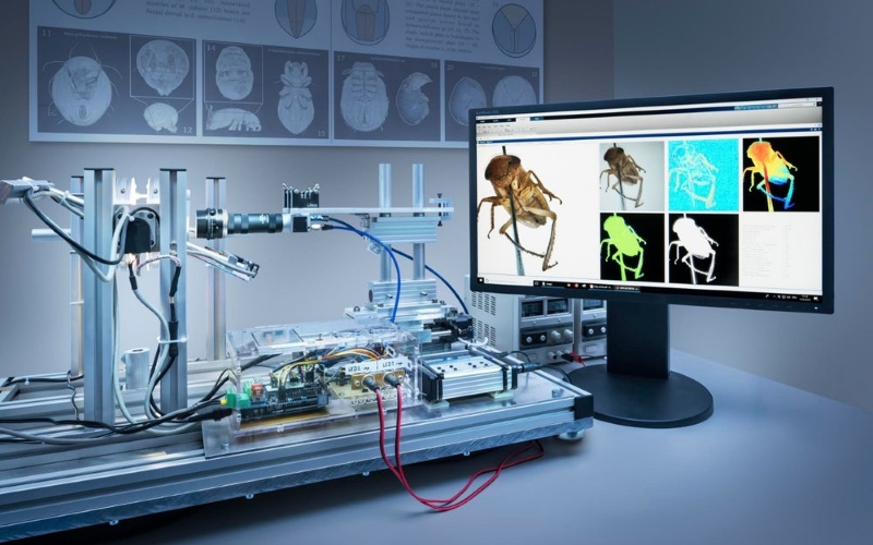 M.T.U
M.T.U
I.M.T.U generate a high-frequency wave signals in search direction, these waves intersect with the signals of magnetic fields released from buried metal targets, then reflected signals are received through a pair of antennas, these received signals are converted into digital signals inside main unit of device and analyzed and visualized on screen.
In MANUAL LRL system, many of scan settings can be adjusted manually by the user according to his preferences before starting the long-range scan, here are the available settings:
- Target
User can choose here the target type, or a type of metal the target is made of, he can choose from preset search programs that include all types of ferrous and non-ferrous metals including:
Gold Treasure- Gold Ore – Silver – Copper – Platinum – Bronze – Iron – Diamond – Gemstones – Gold Veins – Cavity
- Distance
The distance value reflects the scanning field in the forward direction, this value can be set within a range between 0 – 3000 meters from pre-set values:
250 – 500 – 750 – 1000 – 1250 – 1500 – 1750 – 2000 – 2250 – 2500 – 2750 – 3000 m
- Depth
It is the value of the maximum search depth that can be reached using the current search settings, and the value can be set precisely within the range from 0 to 50 meters.
After adjusting the previous search settings, the screen displays a summary of selected settings and user can press (Start Scan) button to start actual scan process.
Result screen display in upper-left corner a digital compass, containing an indicator indicating the geographic direction of the device (for example, towards the north).
In middle of screen there is semi-circle graded scale with direction angle values , zero degree in center and a range of 0-90 degrees in both left and right, an arrow-shaped indicator pointing to specific angle value the represents the direction of movement of the antennas according to the user’s movement when searching.
On the right of result screen Inclination Indicator, this indicator is an important feature allow the user to accurately and correctly adjust the angle of inclination of the device from the horizon, the values with green color – in middle – indicates the correct values, on the other hand the values with red color indicates the wrong values of the inclination angle during scan.
AUTO LRL search system uses I.M.T.U and long-range antennas to search for signals of potential targets within the long-range scan field.
It is advanced search system that covers large areas in open fields of the determined area, this system has the ability to identify all types of buried metals by analyzing captured signals.
Here the user can adjust following settings:
- Distance
It is the distance in front-range (forward direction), can be set in 0 – 3000 m range as explained before in Manual LRL system.
- Depth
It is the maximum depth of possible targets that the device can reach to find potential targets, its value can be set in 0 – 50 m range also like before.
After selecting of previous settings, the user can start the search process, and during search the antennas will move left or right depending on possible nearby targets, a visual indicator on screen will guide the user as it displays a left or right progress bar with gradient colors from green (minimum) to red (maximum value) based on target position.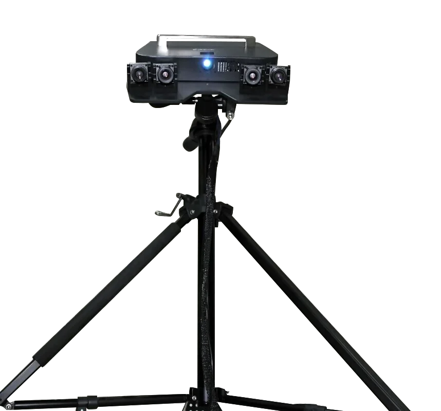
The user must track the movement of antennas tell he got a best signal and after finishing he can move to “Report” screen that will display a visual report about possible target as four horizontal bars (gold – silver – iron – diamond), every bar will display an estimated percentage value that indicate probability of target composition.
CTRL LRL system is one of the new technologies and important features that have been integrated into Gold Star 3D Scanner, that enables the user to set the exact value of the search frequency in order to search for a specific type of metal or alloy of metals based on specific frequency value and thus ensure more accurate results when searching.
In this system, user can set many search-related settings including:
- Soil Type
It is the type of soil of the ground in scan field, can be set to one of following types:
Rock – Mixed – Neutral – Clay – Metallic – Sandy – Mineral – Chalky – Salty
- Frequency
It is the custom frequency the user can set manually using this option.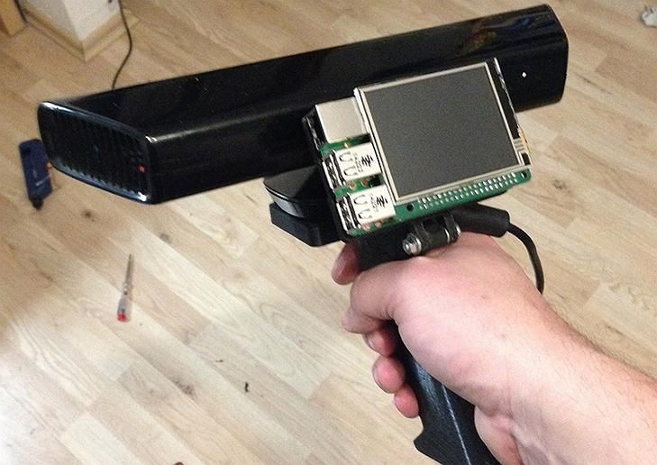
Values range in the 250-5000 MHz range, and can be set from predefined values like 250 – 500 – 750 …. 5000 MHz
- Distance
It is the maximum distance between user location and the target position during the scan process. It means that user can search custom circular distance around himself and this distance start from 0 to 3000 m and can be set like in previous systems.
- Depth
It is maximum depth of possible targets that the device can reach to find, its value can be set in 0 – 50 m range as explained previously.
After adjusting all of previous settings the user moves to scan screen and press “Start Scan” button to begin the search process.
The results screen will display a circular indicator, the direction arrow reflects the direction of antennas in degrees, on the right the inclination indicator that explained previously.
Ionic system uses a new developed technology incorporated into a new probe named Intelligent Multi Transceiver Unit or I.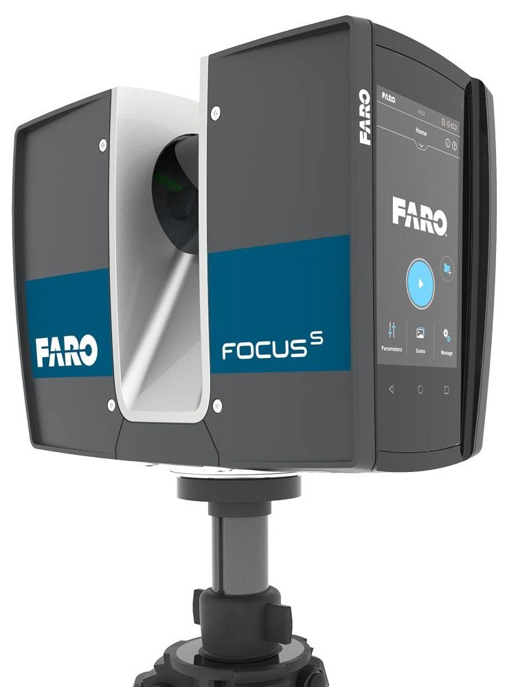 M.T.U.
The I.M.T.U technology is the first of its kind in metal detectors, and it constitutes a major development from the traditional ionic fields detection system found in previous Mega Detection devices or competing devices.
The new technology allows more accurate detection of ionic fields resulting from metallic targets buried under the ground thanks to I.M.T.U that ensures accurate receiving and processing of coming signals, with the ability to control some signal settings on the screen for more accurate results.
After selecting the ionic system, the device will start searching directly, here are the possible settings that can be adjusted by the user:
- Sensitivity
During the search process and according to the target scanning, the ionic system
will generate variable audio tone, it represents the target ability or the distance between user and the target.
The user can change the value of signal sensitivity to analyze the output sound, its value range is between 0 and 100, the selected value shown on Sensitivity circular scale.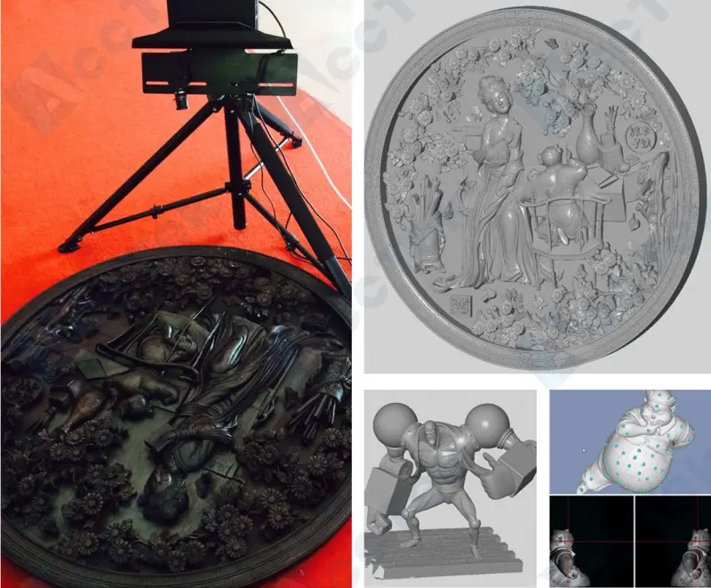
- Gain
It is the signal gain or in other words signal strength, the user can control the signal strength using this setting, and it presented as percentage value (0-100) on circular scale like sensitivity.
Generally, it is recommended to reduce this value for detecting of large-size targets, and increase gain value for small-size targets detection.
In the middle of the screen there is a circular indicator, in the center of it there is a circle whose diameter and color change according to the received signal and the distance of the target from the location of the device, where it shrinks and expands with changing color to one of the following colors (red, blue or green) depending on the type of target.
Based on the received signal, the device also makes an audio tone with pitch and strength related to the position of the target and the nature of the signal.
Bionic system is similar to the Ionic system in terms of how it is work and use of Intelligent Multi Transceiver Unit (I.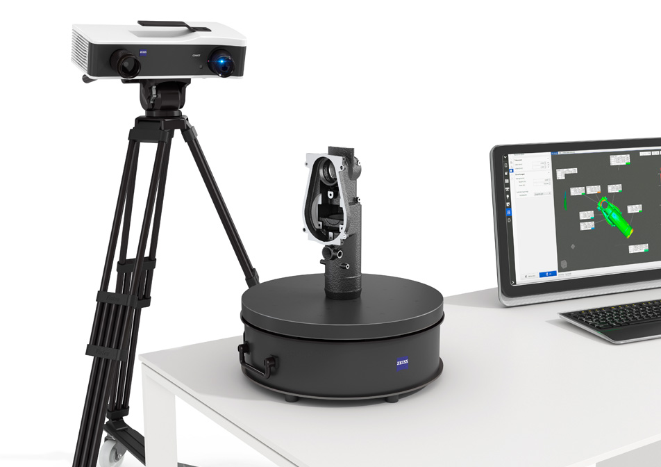 M.T.U) to perform the scan process.
But the difference is that here, ionic signals are captured from a particular metal object. for example, from golden ring or coin, and then the search is directed towards capturing ionic signals similar to metal objects buried underground within the surrounding area.
That mean in the ionic search system, the search is random and free, but in the bionic system the search is directed according to predefined signals.
After selecting the Bionic system and pointing the I.M.T.U to specific target made of the metal that will be searched, the device will start scan for ionic fields in direction of user movement and there are same options as in Ionic system can be adjusted:
- Sensitivity
The user can change the value of signal sensitivity to analyze the output sound, its value range is between 0 and 100, the selected value shown on Sensitivity circular scale.
- Gain
It is the signal gain or in other words signal strength, the user can control the signal strength using this setting, and it presented as percentage value (0-100) on circular scale like sensitivity.
The previous values presented in result screen as circular percentage indicators on right and left sides similar to indicators in Ionic system.
Here there is also a Signal Power or strength indicator displayed below presented as variable-length bars with variable colors and heights based on received signal.
In the center of the screen there is a circular indicator whose movement and colors change according to the type of target and the signal captured with three color possibilities, which are green, red, and blue, related to the type of target.
Based on the received signal, the device also makes an audio tone with pitch and strength related to the position of the target and signal strength.
Live Stream is a system developed to detect various ferrous and non-ferrous metals
in the real time, in form of a live transmission with a visual representation of received signal as specific color stream that reflects the type of the target.
For example: precious metal like gold or bronze – ferrous metal like iron – cavities such as tunnel.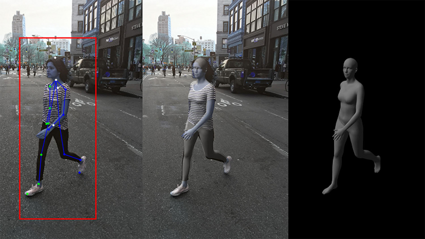
The process of measuring signals or scanning process is carried out by a Vertical High Signal Transceiver (V.S.T) probe, which is a special developed probe, at the end of it there is a quadrilateral cone on both sides of cone there is a set of LEDs that change its colors according to the type of the target , for example the LEDs will emit a red light if the targets is a golden object or blue if it is a tunnel.
The signals captured by V.S.T after calibration represented on the device screen as continuous color stream that changes its color according to the type of possible target , similarly the color is Red when capturing a precious metal signal and green for normal ground , a numeric value related to the target displayed on screen beside the color stream.
In conjunction with the color indicator the device will generate audio tones based on the target type whose signal is captured.
Also, the user can see a visual representation of the signals on the bundled tablet that came with the device within Mega Detection Multi Visual Analyzer app that displays the signal scheme in a graph and the color of the graph will change in a similar way depending on the nature of the signal in other words the type of metal or target.
This powerful search system is a new system with completely new technology designed and developed especially for Mega Detection devices with latest technologies in 3D ground scanning technologies.
This 3D ground scan technology uses a new powerful and unique probe called Multi Ground Scanner (M.G.S) with four built-in sensors and large surface area offering more coverage of ground during scan and reduce the time and effort of scanning large areas quickly with more accurate results.
3D Ground Scan system helps the user to scan the ground and create visual representation on both the device screen or bundled tablet. this system can make searching and find burials and artifacts and even cavities under the ground easy to the user with greater speed and more accuracy.
The settings that can be adjusted on device screen:
- Result Display
The user can select one of two options:
- Device: in this case a scan results will be presented visually on device screen
- Tablet: the scan results will be presented visually on bundled tablet screen using Multi Visual Analyzer app.

- Mode
It is the method of performing the scan procedure and can be set to:
- Manual: here the user will record the measurement of signals in every scan point manually.
- Automatic: in this case the device will record the measurements of every scan point automatically.
- Path
Path value present how user will move in search are to complete the scan process and there are two options:
- One Direction: in one-direction scan the user will move and record the measurements in every point in a scan line and at end of every line, he will return to near the start of previous line but with offset distance to start scanning another line and so on. That mean the direction of scan will be in one direction on every line or all scan lines will be parallel to each other.
- Zig Zag: in this case the start point of next search line is near the end point of previous line or in other words the direction of movement will be opposite for each consecutive lines.
- Size
Here user can set following settings:
- Width: it presents the number of scan lines and can be set to desired value using arrows controls in control panel.
- Height: it is the number of points in every scan line or scan points , it can be set like previous value.
- Start Point
User can set the point in search area (rectangular area that include scan lines and points) where the scan procedure will begin.
- Left: in this case the scan process begins from bottom – left corner of search area
- Right: the scan process will begin from bottom – right corner of search area
After settings of all previous setting the Scan tab will display a summary of previous selected settings and user can press OK on device control panel to start the scan process.
During the scan process the measurement in every scan point will be presented visually on screen on 2D grid consisting of number of rows (scan points) and columns (scan lines) of cells and every cell presented in specific color that reflect the structure of related ground area.
The table below show the type of ground related to each color:
| Green | Light Blue | Blue | Yellow | Red |
| Normal Ground | Small Cavity | Cavity | metal objects | gold |
On the right side of 2D grid there are many values presented:
current x (current scan line number) – current y (current scan point) – search value
After completing the scan in every scan line and point, the scan data can be saved as a file to the device memory for later analysis.
In case that user choose to complete the scan via the tablet, the same settings are set within the Multi Visual Analyzer app installed on tablet, and the scanning is performed by the device in the same way, and the results are displayed directly inside the app in the form of a three-dimensional graphics based on structure of the scanned ground and what it contains of different target types that presented in different colors like in the previous table.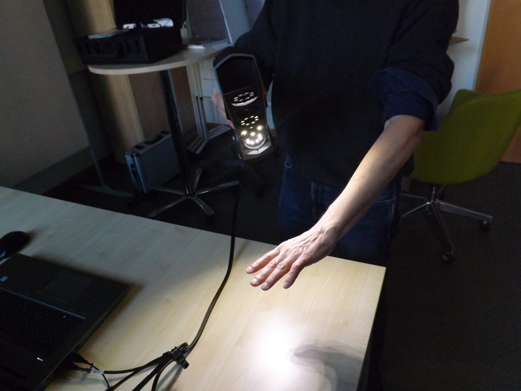
Multi Visual Analyzer app gives the user a more accurate possibility to illustrate and know the buried targets, their type, depth and exact position within the scanned area via its powerful analysis tools.
This system is used to determine the presence of a metal target or cavity with the precise location in which the buried metal or cavity is located via an audio or visual feedback presented on the screen, the process of scanning for possible targets is performed via the V.S.T probe.
In the result screen of this system there are many options:
- Sensitivity
During the search process and according to the target scanning, the pin pointer system will make special scan sound with specific tone and the visual graph on the screen presents the target presence under the ground.
The user can change the value of sensitivity at any time to be able to analyze the output
sound and the accompanied graph.
The value can be set in 0 – 10 range.
- Calibration
User can use this option to calibrate the sensor sensitivity at any time according to the ground type and terrain.
- Reset
Reset the calibration process to default value.
The visual representation of received signals on device screen is a curved bar graph based on type of the target.
For example, in case of receiving metal signals the bar graph will be consisted of rectangles facing upward, of different length, with graded colors from green to red in the center at the maximum values, and then graded towards green with low values.
In the case of receiving cavity signals – such as a tunnel – it will be made of rectangles facing downwards, of different length, ranging from green to dark blue in the middle at the maximum values, and then graded towards green at lower values.
Additional information
Professional OKM Detectors Made in Germany
Detectable Objects
- artifacts
- bunkers
- cavities
- coins / jewelry
- foundations
- natural gold minerals
- gold flitter / nuggets
- metal objects
- military objects
- pipelines
- sarcophagi / treasure chests
- tunnels / tombs
- water-bearing gravel
- water deposits
Operating Mode
- 3D Ground Scan
- Ionic / Bionic
- Geoelectrical Scan
- Live Scan
- Magnetometer / Live Sound
- Mineral Scan
- Pinpointer
- Tunnel Scan
Product Type
- Detection Equipment
Scan Procedure
- 3D Ground Scan (GST / EMSR)
- Geoelectrical measurement
- Long-range detection
- Ground penetrating radar
- Metal detection (SRIS)
- Metal detection (VLF / PI)
Special Feature
- incl.
 Android App
 - GPS
- Orientation Sensor
- incl. Visualizer 3D Studio
Use Case
- Agriculture
- Archaeology
- Cavity Detection
- Explosive Ordnance Disposal
- Forensics
- Geotechnical Engineering
- Militaria Detection
- Natural Gold Prospection
- Public Services
- Treasure Hunting
- Water Detection / Well Building
FeaturedName AscendingName DescendingDate AscendingDate DescendingPrice AscendingPrice DescendingBest Selling
Add to wishlist Add to compare Add to wishlist Add to compare-
OKM Fusion Light
EUR 4. 490,00 plus VAT*
More details »
EUR 4.490,00
plus VAT*
Add to wishlist Add to compare Add to wishlist Add to compare-
OKM Bionic X4
EUR 9.785,00 plus VAT*
More details »
EUR 9.785,00
plus VAT*
Add to wishlist Add to compare Add to wishlist Add to compare-
OKM Pulse Nova
EUR 1.990,00 plus VAT*
More details »
EUR 1.990,00
plus VAT*
Add to wishlist Add to compare Add to wishlist Add to compare-
OKM Rover C4
EUR 9. 490,00 plus VAT*
More details »
EUR 9.490,00
plus VAT*
Add to wishlist Add to compare Add to wishlist Add to compare- AS SEEN ON TV
OKM eXp 6000 Professional Plus
EUR 29.490,00 plus VAT*
More details »
EUR 29.490,00
plus VAT*
Add to wishlist Add to compare Add to wishlist Add to compare-
OKM Evolution NTX
EUR 5.490,00 plus VAT*
More details »
EUR 5. 490,00
plus VAT*
Add to wishlist Add to compare Add to wishlist Add to compare-
OKM Fusion Professional Plus
EUR 12.990,00 plus VAT*
More details »
EUR 12.990,00
plus VAT*
Add to wishlist Add to compare Add to wishlist Add to compare- AS SEEN ON TV
OKM eXp 6000 Professional
EUR 20.990,00 plus VAT*
More details »
EUR 20.990,00
plus VAT*
Add to wishlist Add to compare Add to wishlist Add to compare-
OKM Fusion Professional
EUR 6. 990,00 plus VAT*
More details »
EUR 6.990,00
plus VAT*
Add to wishlist Add to compare Add to wishlist Add to compareNEW-
OKM Rover UC
EUR 7.990,00 plus VAT*
More details »
EUR 7.990,00
plus VAT*
Add to wishlist Add to compare Add to wishlist Add to compare- AS SEEN ON TV
OKM Gepard GPR 3D
EUR 18.490,00 plus VAT*
More details »
EUR 18. 490,00
plus VAT*
Add to wishlist Add to compare Add to wishlist Add to compare-
OKM eXp 4500 Professional Plus
EUR 21.990,00 plus VAT*
More details »
EUR 21.990,00
plus VAT*
Add to wishlist Add to compare Add to wishlist Add to compare-
OKM GeoSeeker
EUR 8.490,00 plus VAT*
More details »
EUR 8.490,00
plus VAT*
Add to wishlist Add to compare Add to wishlist Add to compare-
OKM eXp 4500 Light
EUR 11.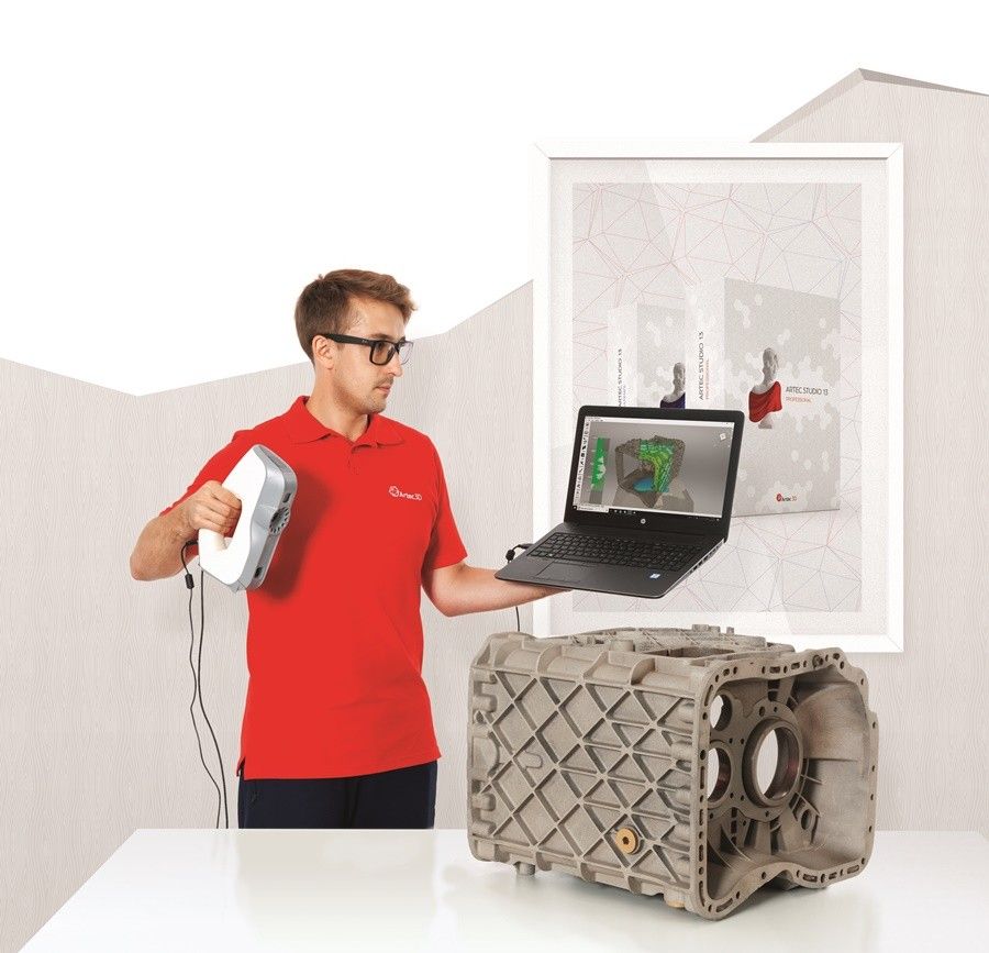 990,00 plus VAT*
More details »
EUR 11.990,00
plus VAT*
Add to wishlist Add to compare Add to wishlist Add to compare- UPON REQUEST
OKM 3D Ground Navigator
EUR 10.500,00 plus VAT*
More details »
EUR 10.500,00
plus VAT*
Add to wishlist Add to compare Add to wishlist Add to compare-
OKM eXp 4500 Professional
EUR 13.990,00 plus VAT*
More details »
EUR 13.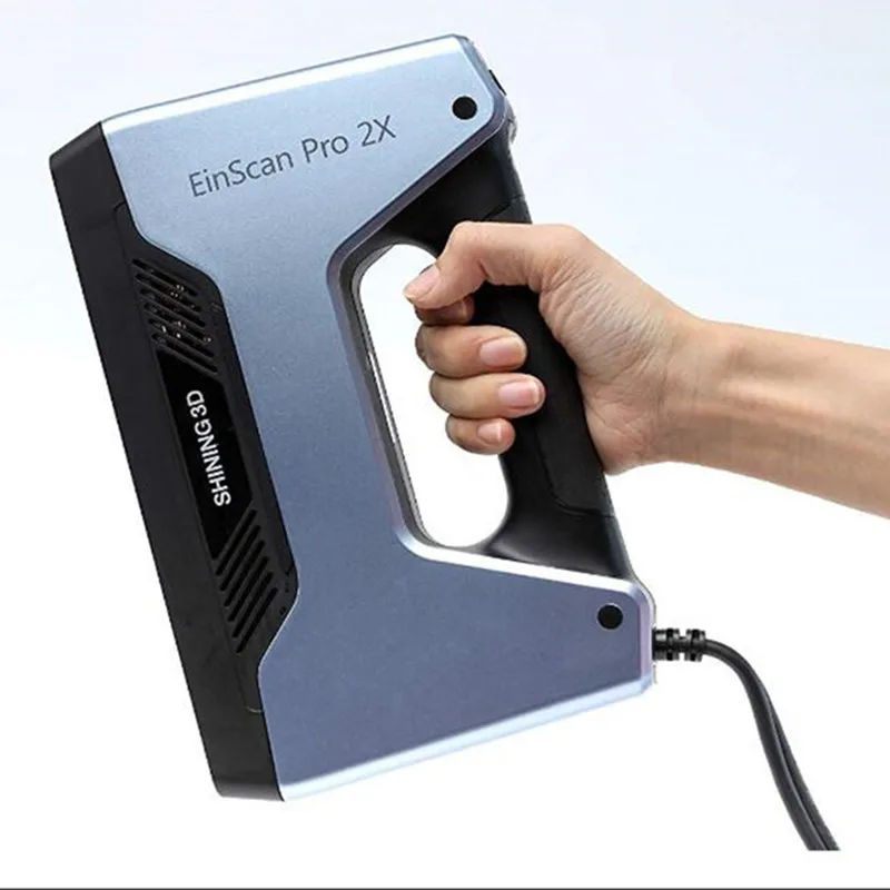 990,00
plus VAT*
Add to wishlist Add to compare Add to wishlist Add to compare-
OKM GeoSeeker Mini
EUR 5.990,00 plus VAT*
More details »
EUR 5.990,00
plus VAT*
Please login and you will add product to your wishlist
Sign In Register
Desktop 3D Scanners - EinScan Multifunctional 3D Scanner
Get a quote
Please fill out this form to receive a free quote within 24 hours (during working days).
AfghanistanALAND ISLANDSAlbaniaAlgeriaAmerican SamoaAndorraAngolaAnguillaAntigua And BarbudaArgentinaArmeniaArubaAustraliaAustriaAzerbaijanBahamasBahrainBangladeshBarbadosBelarusBelgiumBelizeBeninBermudaBhutanBolivia, Plurinational State OfBosnia And HerzegovinaBotswanaBouvet IslandBrazilBritish Indian Ocean TerritoryBrunei DarussalamBulgariaBurkina FasoBurundiCambodiaCameroonCanadaCape VerdeCayman IslandsCentral African RepublicChadChileChinaChristmas IslandCocos (Keeling) IslandsColombiaComorosCongoCook IslandsCosta RicaC?te D'IvoireCroatiaCubaCyprusCzech RepublicDenmarkDjiboutiDominicaDominican RepublicEcuadorEgyptEl SalvadorEquatorial GuineaEritreaEstoniaEthiopiaFalkland Islands (Malvinas)Faroe IslandsFijiFinlandFranceFrench GuianaFrench PolynesiaFrench Southern TerritoriesGabonGambiaGeorgiaGermanyGhanaGibraltarGreeceGreenlandGrenadaGuadeloupeGuamGuatemalaGuernseyGuineaGuinea-BissauGuyanaHaitiHeard Island And Mcdonald IslandsHoly See (Vatican City State)HondurasHong KongHungaryIcel andIndiaIndonesiaIran, Islamic Republic OfIraqIrelandIsle Of ManIsraelItalyJamaicaJapanJordanKazakhstanKenyaKiribatiKorea, Republic OfKosovoKuwaitKyrgyzstanLao People'S Democratic RepublicLatviaLebanonLesothoLiberiaLibyan Arab JamahiriyaLiechtensteinLithuaniaLuxembourgMacaoMadagascarMalawiMalaysiaMaldivesMaliMaltaMarshall IslandsMartiniqueMauritaniaMauritiusMayotteMexicoMicronesia, Federated States OfMoldova, Republic OfMonacoMongoliaMontenegroMontserratMoroccoMozambiqueMyanmarNamibiaNauruNepalNetherlandsNetherlands AntillesNew CaledoniaNew ZealandNicaraguaNigerNigeriaNiueNorfolk IslandNorthern Mariana IslandsNorwayNORTH KOREAOmanPakistanPalauPalestinian Territory, OccupiedPanamaPapua New GuineaParaguayPeruPhilippinesPitcairnPolandPortugalPuerto RicoQatarReunionRomaniaRussian FederationRwandaSaint BarthélemySaint HelenaSaint Kitts And NevisSaint LuciaSaint MartinSaint Pierre And MiquelonSaint Vincent And The GrenadinesSamoaSan MarinoSao Tome And PrincipeSaudi ArabiaSenegalSerbiaSeychel lesSierra LeoneSingaporeSlovakiaSloveniaSolomon IslandsSomaliaSouth AfricaSpainSri LankaSudanSurinameSvalbard And Jan MayenSwazilandSwedenSwitzerlandSyrian Arab RepublicTaiwan, Province Of ChinaTajikistanTanzania, United Republic OftestThailandTimor-LesteTogoTokelauTongaTrinidad And TobagoTunisiaTurkeyTurkmenistanTurks And Caicos IslandsTuvaluUgandaUkraineUnited Arab EmiratesUnited KingdomUnited StatesUruguayUzbekistanVanuatuVenezuela, Bolivarian Republic OfViet NamVirgin Islands, BritishVirgin Islands, U. S.Wallis And FutunaWestern SaharaYemenZambiaZimbabweMACEDONIASOUTH GEORGIADemocratic Republic of the Congo
* Which product are you interested in?* Desktop 3d scanner* Hybrid light source handheld 3d scanner* Multifunctional handheld 3d scanner* Multiple scan range 3d scanner* Other Products and Service
submit...
Intergeo 2013. Essen. germany. Laser scanning / Habr
Hello, dear Habra community.
The event, about some aspects of which I would like to tell you, can be classified as very widely known in narrow circles. Let me say a few words about what Intergeo is.
This is an exhibition of the achievements of the geodetic and cartographic economy, which has been held annually in Germany for more than 20 years. There is simply no larger event that would affect such areas as geodesy, cartography, photogrammetry, GIS and spatial modeling in the World. There are large leadership workshops, but they are usually based around a single brand (eg ESRI).
That is why at Intergeo you can evaluate the current development of many areas, see the latest developments, find direct contacts with manufacturers. The participation of the company at this exhibition can be directly assessed as its positioning in the world market.
Initially, I planned to make a post-review of all the directions presented at the exhibition, but after analyzing the materials collected at the exhibition, I realized that it would take me several weeks to do this, since I now have such diverse information. Therefore, in this post we will talk only about one, young and promising direction, which has recently gained such momentum that it is impossible not to pay attention to it. I propose to discuss the current state of laser scanning (with a slight bias towards 3D modeling).
Separately, I would like to point out that the following aspects of the exhibition interested me primarily as a geodetic engineer.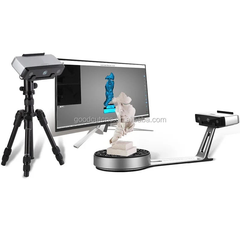
Let's start with a short digression into history, albeit not far off. The development of digital surveying technology, in particular laser rangefinders, quite predictably led to the first attempts to assemble a laser scanner. The first mention of such devices dates back to the mid-90s. For example, Cyberware released in 1991 a device capable of scanning small objects; these scanners were supposed to be used in medicine. For geodesy, these devices were not suitable, but the principles had already been determined.
The first geodetic scanners appeared under the Cyrax brand model 2400 in 1998, around the same time the RIEGL Scanner LMS Z 210 was released. Cyrax was bought by Leica three years later, while Riegl exists on the market to this day as an independent manufacturer.
In a few words I will describe what a laser scanner does and why it is needed. In essence, the scanner, like the total station, is a goniometer with a laser rangefinder. The only difference is that the scanner performs a very large number of measurements per unit of time, rotating the measurement plane around its axis. Scanning, thus, the space around him.
Trimble GX laser scanner in front of the building being scanned. Taken from Navgek Engineering
At the output we have a "scan" - a cloud of points, which is characterized by low discreteness, and under certain conditions can be perceived as continual. Why is it needed. If we have an object with complex outlines (for example, an industrial plant, or the facade of a historical building, etc.), then it is very difficult to reproduce its mathematically accurate image with traditional geodetic tools. The scanner is faster and easier (but not always).
Point cloud. Taken from Navgek Engineering
From the very beginning, laser scanning competed with photogrammetry, which allows you to do almost the same thing, but with a sufficient number of additional conditions. But it's cheaper. There was anyway. As long as scanning wins.
What is usually scanned? Architecture - especially old facades, industrial enterprises with a bunch of pipes, passages, etc. , volumes - tanks, plugs, interior spaces. In land surveying and cable laying, scanners are rather useless.
Naturally, this technology did not pass by active players. All leaders of the geodetic market zealously took up the development (or buying up) of technologies. At the moment, only Javad does not boast of its scanning solution (because it is completely focused on GPS). Leica, Trimble, Topcon make scanners. Along with them are Z + F, Riegl, Faro - specialized manufacturers of exclusively scanners. Once upon a time, even UOMZ intended to release a scanner and even sawed a prototype out of plywood, but somehow this did not work out further. The mention is on the omniscient "surveyor". Although the Russian scanner Surphaser exists.
At this stage, laser scanning can be divided into the following segments: terrestrial laser scanning and mobile laser scanning.
As for , the ground part of is the main niche of laser scanners. The main competition is for technical characteristics - who is further, denser and more accurate can create a cloud of points. Well, faster, of course. Everyone participates in the competition. Another trend is to reduce the size of the scanner, here, the leader is Faro, whose scanner is no larger than a toaster.
The latest trend is to integrate a controller screen into the scanner body itself from which control operations can be performed. The monitor is small, but now the software for controlling the scanner from a laptop can be sold separately (for example, Leica and their Cyclone). Leica P20, Trimble TX5, TopCon already have such scanners. The latter, however, presented a scanner at the exhibition, for which there is no information at all, there is no model. And attempts to create a scanning zone using the internal controller were stopped by the manager with the wording "this function is in the scanner, but there are no menu items for it."
Z+F scanner with controller side shield.
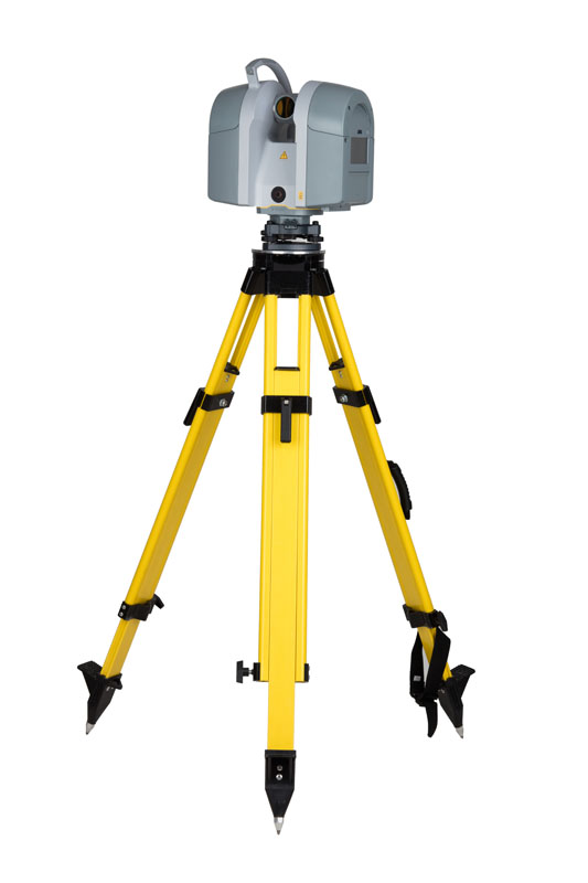
Consider the Leica P20 scanner as the most typical representative of the segment. Range - 120 meters (quite a lot for a phase scanner), accuracy 3 mm at 50 m, 6 mm at 100 m. Capable of scanning with a resolution of 0.8 mm at a distance of 10 m, while the scanning time will take about 1.5 hours. Weighs 12 kg, dimensions 24*35*40 cm.
Scanner Leica P20. Image taken from here
For these devices, there is another parameter that, unfortunately, cannot be objectively assessed - this is exposure to the influence of the external environment. None of the manufacturers provide statistics on equipment breakdowns. In other cases, this is the main determining criterion. Often, firms that are actively involved in laser scanning immediately purchase 2 scanners, realizing that after the first projects, one of them will go to the service. It is impossible to determine the viability of a particular model except by word of mouth. Leica P20, according to random opinions, is "survivable". The manufacturer assigned it an IP54 class and an operating temperature range of -20 to +50. Even 5 years ago, such parameters were a fairy tale, and scanners were dressed in covers with thermochemical heating elements in winter.
A surprise in this segment is the outwardly modest Hi-Target scanner. It is unremarkable, except that it is the first independent Chinese scanner. How it works is the big question. But this is the first sign from Asian friends, so they also try their hand at geodetic Hi-End. As for the Low-End, after the exhibition one inevitably gets the impression that only the laziest Chinese has not yet soldered a dual-system geodetic GPS receiver and has not assembled a digital total station. It's time for the scanners.
China's first Hi-Target scanner
Mobile laser scanning is a trend of recent years. Similar solutions have been met before, but, perhaps, only this exhibition showed that all the leaders of the geodetic market rushed into this niche.
Each of the leaders demonstrated similar systems on different media. Leica, Trimble, Topcon, Riegl, Faro placed laser scanners on cars. The devices are very similar in parameters, so let's turn to the Trimble MX2 mobile laser scanner, presented on the roof of the Mini.
Trimble MX2 Roof Scanner Mini
Of course, the first thing that matters is accuracy. This device claims 10 mm at 50 meters. Such accuracy is achieved due to the installed inertial system, coupled with 2 satellite antennas, the accuracy of which during post-processing is declared in the range from 2 to 5 mm. 360 degree visibility. The range is 250 m, but most likely, at such a distance, the accuracy will drop to 5 cm.
The second thing that interests you is at what speed can you scan? Trimble doesn't have this information directly, so we have to turn to Leica data with their HDS7000 scanner built into the Pegasus: One photosystem. Most likely, you will have to limit yourself to 40 km / h. According to representatives at the booth, the speed can be maintained even at a high speed (for example, when shooting highways), but then the cloud turns out to be sparse, and the way out can be found in the repeated passage of the scanner along the highway.
Scanner HDS700 Leica
Probably worth mentioning the cost of these devices. A laser scanner is far from being a cheap tool, and when buying such a ground-based device, you should count on a price starting from 80,000 Euros. As for the mobile solution, when buying "all inclusive" the price of the issue increases by about 4-5 times. No one will clearly tell the exact price in Russia for new devices, only an approximate order.
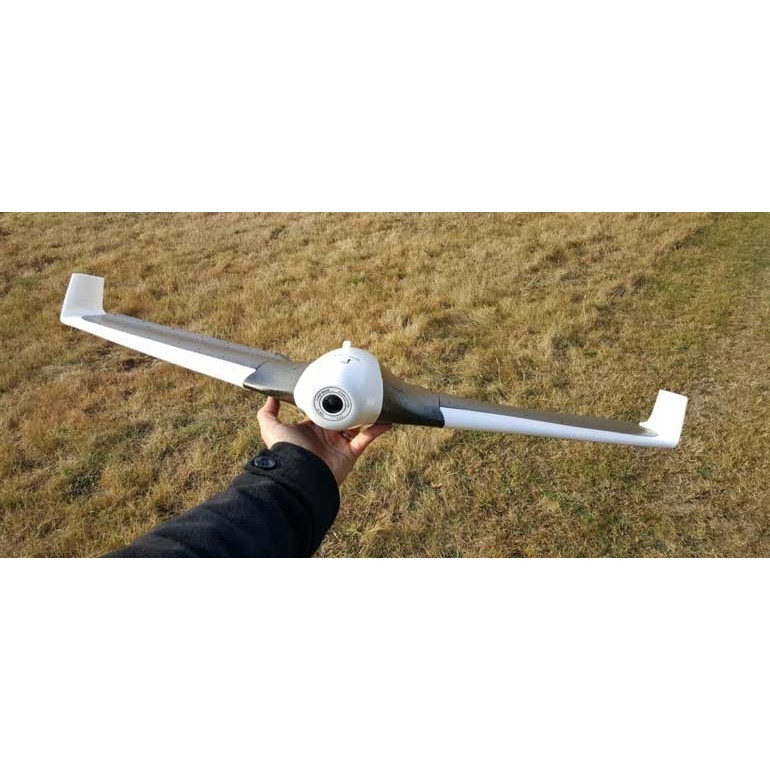
Separately, I would like to note 2 derivative solutions. The first is the Faro scanner (exactly the one with the size of a toaster), mounted in a quadrocopter.
Faro flying scanner
The manufacturer positions it as an ideal solution for architectural photography, with an accuracy of up to 10 mm. The bottom line is that the points that define the contours of the building are preliminarily taken with a total station, and then a route is laid in the quadcopter controller, along which the scanner makes a flyby. Why is this fundamentally better than ground shooting - guaranteed coverage of dead zones. From the ground, it is a big problem to remove the roof and the upper elements of architectural details. In practice, often these details are extrapolated, and the objectivity of the reflection is in question.
What makes this solution worse is that it is less accurate (a ground-based scanner can provide 2-3 mm of accuracy), and also not yet protected. To my question - what kind of protection does this scanner have from water and dust, the representative answered modestly that none. Recalling my personal experience of scanning metallurgical plants, where metal dust hangs in the light in the air, I can say that this device flies, most likely, not for long.
Riegl ship scanner
The second solution is the Riegl VMS-250 scanner. There is no information on it yet on the network, but we should expect that its characteristics are similar to other mobile scanners. This company went further in positioning the scanner and offers to place it not only on cars, but also on trains (they even completed a pilot project between St. Petersburg and Moscow), as well as on small boats. The global idea is that it is incredibly difficult (or simply impossible) to remove many surface structures: bridges, platforms, piers with a ground-based scanner, but approaching on a yacht with a scanner is a completely reasonable decision.
Theoretically, these two solutions above could compete. Those. one could choose to fly up to the structure or swim up. But Faro has an unfinished solution, while Riegl is already ready to supply this system, including to the Russian market.
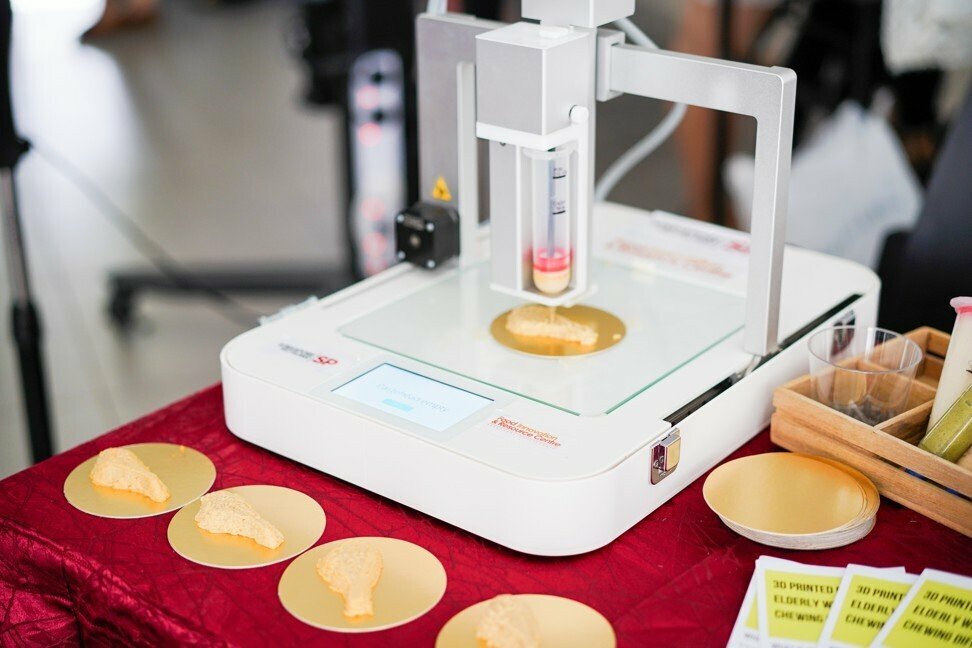
It should be noted that in addition to these two segments, there were two more scanning directions on the market - manual model scanning, i.e. With the device, you can scan a person and lidar from a helicopter (a very old direction that began even before ground-based scanners). For certain reasons, I did not pay much attention to them (the first is not applicable to geodesy, the second is quite understandable anyway - low accuracy and problems with vegetation, while the cost and complexity of organizing in the Russian Federation).
Manual human scan. Presentation.
Scanning problems lie not only in the laser scanners themselves, but also in the processing of the resulting material. Typically, the workflow looks like this:
Scanning - Stitching scans - modeling in the scanner manufacturer's software - exporting to CAD - finalizing the model - obtaining drawings from the model - drawing up drawings.
At each of the above stages, solutions are applied that are far from ideal. It makes no sense to list all the problems, but at each stage the software is brought to mind.
Leica Cyclone allows you to stitch scans not only by spheres (in order to connect adjacent scans, standardized balls are hung on the object, their recognition by software allows you to reduce the point cloud), but also by structural elements (for example, bends of pipes, ends of metal structures - channels) , assigning them the role of spheres.
Cubit software eliminates the modeling step in the manufacturer's software, allowing point clouds to be entered directly into CAD.