3D scanner diy arduino
6 DIY 3D Scanners You Can Build at Home
Creating a 3D model of a real object can be done extremely fast if you have a 3D scanner at home. The problem is: 3D scanners are expensive to buy new.
If you're looking for a solution, why not try building your own affordable 3D scanner at home? It might not create perfect 3D models, but it's a cost-effective alternative to buying a 3D scanner.
Is It Cheaper to Build a DIY 3D Scanner?
The cost of buying a decent 3D scanner ranges from $700 to $10,000 at the highest end. On the other hand, building a DIY 3D scanner can cost less than $200—some even as little as $35.
Depending on the resolution of your homemade 3D scanner, you will still have to work to tidy up the 3D model so that it can be used for things like 3D printing, game development, or perhaps design prototyping. But overall, it will still speed up the design process when compared to building a model from scratch.
1. Cheap 3D Printed 3D Scanner
This 3D scanner is built using 3D printed parts, featuring both open source software and open source hardware files. If you choose to install the maximum of four lasers, then the cost of the project comes in at $35 to $50. Once it's built, handling the digital scan will require some legwork to smooth out. But considering its price tag, it's well worth giving it a go.
You can find the STL files and a full build guide on Instructables. Besides the 3D printed components, you will need one to four lasers, a stepper motor, a turntable, and an Arduino Nano to bring it all together. One benefit of this project is that it's been built many times by community makers, resulting in plenty of images and feedback surrounding the project to help fill in any gaps.
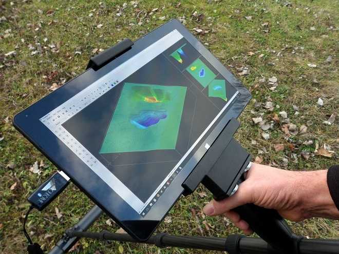
2. DIY 3D Scanner Using a DSLR Camera
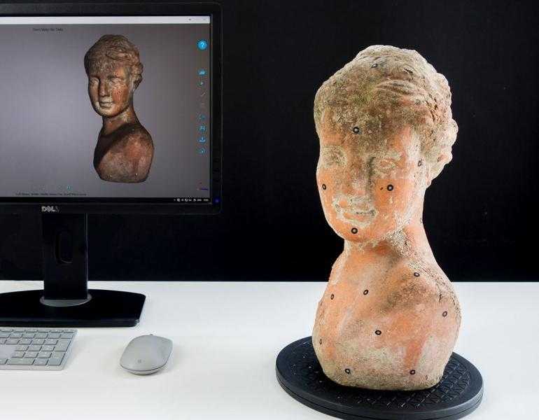
Another option for building a 3D scanner is to use a DSLR camera and a method called photogrammetry. At its most basic, it involves taking a lot of images of an object from different angles and stitching those photos together in a software program to create a 3D model.
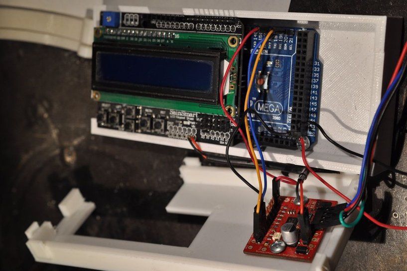
Alongside a DSLR camera, you will need an Arduino, a stepper motor and driver, an LCD screen, and an IR LED.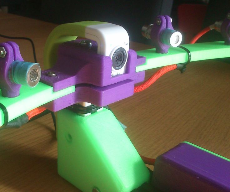 The goal of the hardware is to build a rotating platform that moves by set amounts so that your camera can photograph the object in a very detailed and controlled way. You can find a great explanation of the project on Instructables.
The real difficulty of this project comes in processing the photos. A good photogrammetry program is essential, and that can cost over $150 to license. There is some free software available, but it may come with limitations.
If you're wondering if there is an alternative solution, you can read our guide to how to turn everyday objects into 3D models without a 3D scanner.
3. Optical CT/3D Scanner With Arduino
For something a little different, in this project you will build a 3D scanner that also doubles as an optical CT scanner. This type of scanner will do the trick if you have objects that are semi-transparent, like a gummy bear or a segment of orange. Otherwise, you can use this setup with the photogrammetry method for regular 3D scans.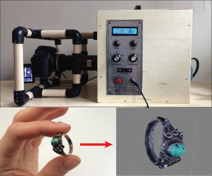
Everything in this build is enclosed inside a box. This allows greater control over lighting the object to produce sharper images. While it involves some woodworking and construction, the hardware is still powered by a humble Arduino Nano, plus additional parts that you can find at any hardware store.
A great guide is available on Instructables for building the box, alongside details for creating a sleek control panel for changing photo parameters on the go.
4. FabScan: Raspberry Pi + Arduino 3D Scanner
This 3D scanner uses both a Raspberry Pi and an Arduino to build a 3D laser scanner. What sets this build apart is that it can be operated remotely via a web browser on a phone.
Much like other DIY 3D scanners, a stepper motor and driver are used to rotate a turntable holding the object you want to scan. Additionally, you will need a line laser and a Raspberry Pi camera. You can find the guide and a full components list on Instructables.
While the creators have gone with a laser-cut MDF box, you can just as easily use spare parts lying around the home to create the enclosure. Alternatively, cardboard can work too, and painting it black will aid in diffusing the laser light so that it doesn't interfere with the scan.
Once you have a good scan of your object, you might be interested in 3D printing it. Haven't got a 3D printer? Here is our pick of the best 3D printers.
5. The Ultimate Human Sized 3D Scanner With Raspberry Pi
While most homemade 3D scanners are built to capture a small object, it's also possible to build a human-sized 3D scanner. The way to do this is with a lot of Raspberry Pis, as you can see over on Instructables.
The maker behind this project scaled up his 3D scanner using a whopping 47 Raspberry Pis plus a Raspberry Pi camera for each module. The goal was to use the photogrammetry method to take a photo of his subject from every possible angle. Because he wanted to capture a 3D model of his two-year-old son, this all had to happen instantly.
Incredibly, it works, and it works very well too. If you have the time and investment to buy a box full of Raspberry Pis, you won't be disappointed because the results are impressive.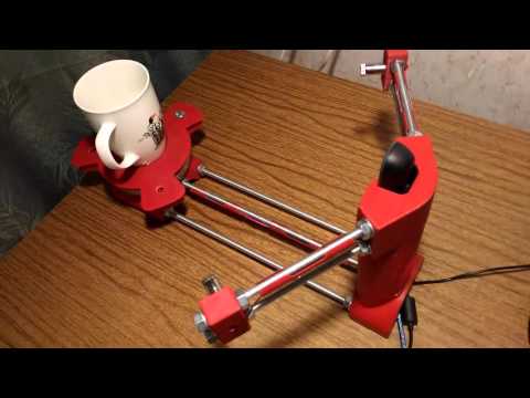 The maker says you can use fewer Pis and cameras and still get good results, especially if you only need to capture the front of a person’s face.
6. Standalone 3D Scanner
Maybe you're just after a simple and small 3D scanner that you can make over the weekend. If so, then this project will suit you. This 3D scanner on Instructables is designed to be all-in-one, meaning that the photos are compiled onboard and an STL file is saved directly to a memory card. Instead of compiling the photos in a separate photogrammetry program, this 3D scanner handles them for you.
While it doesn't produce incredibly detailed scans, it does make for a rapid way to take a 3D model straight to 3D printing. One thing to bear in mind, however, is that the dimensions of the 3D scanner structure need to be kept exactly as written in order to match the code.
Building a Homemade 3D Scanner
Putting together a 3D scanner at home isn't extremely difficult to achieve. When compared to the expensive price of commercial 3D scanners, it's well worth building a DIY 3D scanner yourself.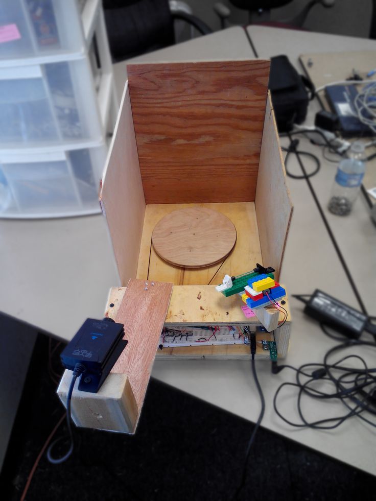
With a Raspberry Pi or Arduino and a few extra affordable parts, you'll be well on your way to creating a cheap and awesome 3D scanner.
3D scanner with Arduino and very cheap photogrammetry
Being able to have a 3D scanner at your disposal is something very interesting. Especially if you must regularly reproduce and print organic models, since drawing them can be a real nightmare.
A 3D scanner allows you to digitally capture the shape of any physical object, either using laser light or by photogrammetry. Basically you will create a point cloud made up of a set of vertices in a three-dimensional coordinate system (X, Y and Z). This will precisely form the outer surface of the object in question.
Today in 3DWork.io, I desire to show you an interesting way of how to build a 3D scanner with Arduino and photogrammetry. The only thing you will need is an Arduino UNO board, a 3D printer and some extra components, in this way you can prepare your own inexpensive and fully functional 3D scanner.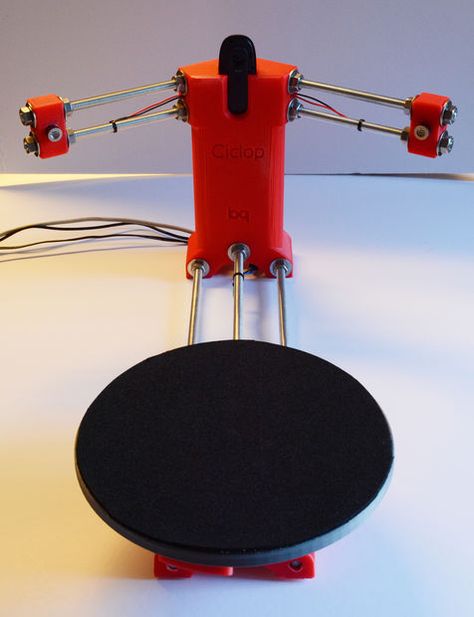
So let’s get to it …
3D scanner with Arduino and photogrammetry
Its operation is based on photogrammetry, a technique used by some 3D scanners to generate 3D objects from photographs taken on a model. It would actually be something like “measuring” photos, if it could be called that 🙂
This 3D scanner has been made by the user Bribro12 , and is a new and improved version of a previous existing design of yours on Thingiverse, but this time fully automated and with Bluetooth connectivity to smartphones.
A single 3D scanner, but 3 functionalities available
The design presented by Bribro12 is not just another turntable as it might seem. This 3D scanner captures 360º photos of the object with a mobile phone connected to Bluetooth, all managed by a Bluetooth remote control that makes small advances in the platform.
It also allows us to define the number of photos to take, from 2 to 200, simply configuring from the same Arduino program. You can then convert all these photos into a 3D model using any available photogrammetry software, such as Autodesk Recap Photo.
It also offers us the possibility of using it to take photos or cinematographic shots of objects by setting the rotation of the platform at a certain speed. This can vary between 1RPM and 17RPM, which are the speeds of the stepper motor.
A third option would allow us to manually control the turntable, being able to bring it to the desired position and at the preferred speed. As you can see, it is a fairly complete application.
In the video you can see the complete process of the design and construction of the turntable, the servo drive for the advance of the platform and much more. The truth is that it is a very interesting project, everything must be said.
Required components
This is a list with the components that appears in today’s article. It is my duty to inform you that they are affiliate links to different internet online stores.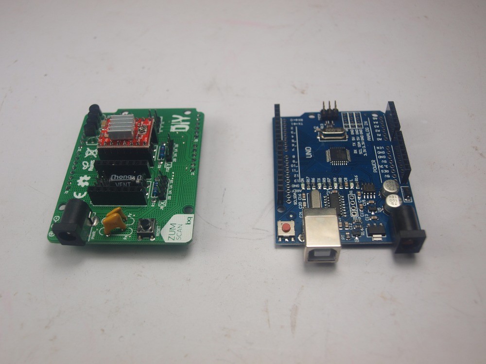
If by chance you use them, the price of the product will be the same as if you access them regularly. And 3DWork will have a small commission that will help maintain and give continuity to this website.
| Arduino UNO R3 ATmega16U2 | |||
| SG90 Mini Gear Micro Servo 9g | |||
| Geekcreit® 40pcs FR-4 2.54mm PCB | |||
| Geekcreit® IIC / I2C 1602 LCD Display | |||
| Multifunctional BT Remote Control | |||
| LM2596 DC-DC Verstellbar Step Down | |||
| 28YBJ-48 DC 5V Wire Stepper Motor | |||
| JoyStick Module Shield 2.54mm |
Project files
| Enlaces de descarga | ||
| Required STL files | direct link | |
| Wiring diagram arduino (Electric scheme) | direct link | |
| Camera Turntable Arduino (Software) | direct link | |
We hope that this short project to make a 3D scanner with Arduino from scratch has been useful for you.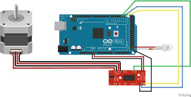 If so, do not hesitate to indicate it in your comments at the end of the article. You can find more information about it on Thingiverse by clicking on this same link.
Finally, I would like to remind you that we have a great community in our Telegram channel.
Finally, you can find more interesting articles here:
- Post-processing of 3D parts: Much more resistant and airtight with heat and salt
- Marlin Builder: Update with support for version v2.0.6.1 and factory preconfigured firmwares
- Monoprice Cadet: Safe 3D printing for kids and beginners
- New review of electronic BTT SKR MINI E3 V2.0 for your Ender 3 printer
- Closed-Loop Motors: Makerbase MKS Servo42b (Brief analysis)
- Complete guide SKR v1.4 / v1.4 Turbo with TMC2209 Sensorless drivers and Display TFT35 V3.0
- DyzeXtruder Pro: Analysis of a high-performance extruder for professional environments
- MKS TFT35 Display: Latest updates v106 and v107 available
- The Spaghetti Detective: Monitoring Octoprint from the Internet safely
90,000 Homemade 3D scanner AASCAN
News
Subscribe to the author
Subscribe
I do not want
14
Enthusiast under the nickname QLRO posted the project of a simple desktop photogrammetric 3D scanner assembled from smartphone, microcontroller arduino and 3D 3D - printed parts.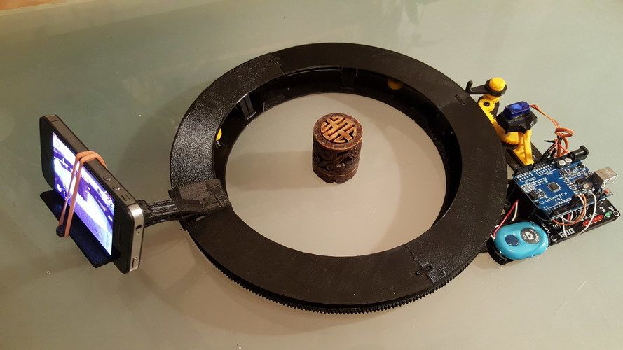
To assemble the device, you will need a minimum of components, plus an Android smartphone and a computer. The rotating platform and smartphone stand can be 3D printed. In the original project, the platform is rotated by a 28BYJ-48 stepper motor with an ULN2003 driver and controlled via Arduino. Scanning is carried out by photogrammetry, using the built-in camera of a smartphone.
The system relies on Meshroom photogrammetry software. As the developer explains, the software requires the use of an Nvidia graphics card with CUDA hardware and software architecture. The operation of the device components is coordinated by scripts written in Python: the computer sends commands to the Arduino and the smartphone to rotate the platform and shoot, and after shooting the object from all angles, the images are converted into a digital model. In the current, third version of the software, it is possible to use several cameras at the same time, but so far on an experimental basis.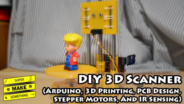
The author posted all the necessary files and instructions in the public domain on the Thingiverse website at this link.
3D scanner desktop AAScan QLRO
Follow author
Follow
Don't want
14
Article comments
More interesting articles
fourteen
Subscribe to the author
Subscribe
Don't want to
It used to be that in cases of revocation of airworthiness certificates for storks and poor harvest of cabbage, children came . ..
..
Read more
5
Follow author
Subscribe
Don't want
Experts from the Institute of Light Materials and Technologies (ILMT) of the united company RUSAL have developed...
Read more
82
Subscribe to the author
Subscribe
Don't want
Collaboration 3D
We are pleased to present you our joint development with Speci...
Read more
Arduino CNC | Contact 3D Scanner | Manufacturing
We continue to refine a simple CNC machine on Arduino. Now we make a contact 3D scanner out of it. The mechanical part is extremely simple. Significant improvement will be required for the firmware of the Arduino board, as well as for the machine control program.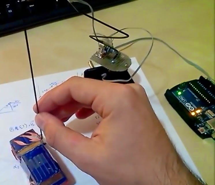
Producing a contact probe for a 3D scanner
To create a 3D scanner from an existing Arduino-based CNC machine, we need a contact sensor. To make it, you will need two metal strips, two nails, a rail, a resistor with a resistance in the range of 1Kom-10Kom and wires. The finished sensor does not look very presentable, but it performs its functions. In the future, you can make a more aesthetic and accurate version of the sensor. The sequence of manufacturing parts of the sensor and its assembly is clear from the photo.
Photo of a contact sensor for a 3D scanner. We attach two brackets of iron strips to the rail. A nail is threaded into each bracket. The nail falls down under the action of gravity (you can put springs from fountain pens). There is a small gap between the sharp end of the top nail and the head of the bottom nail. Now, if the lower nail (probe) rests against the scanned object, it rises along the rail and touches the tip of the upper nail.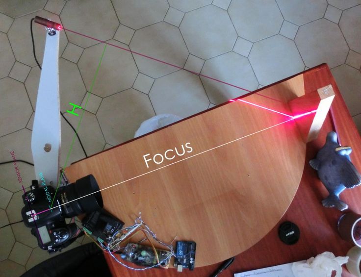 Thus, the sensor circuit will be closed and a HIGH signal will appear on the digital pin 2 of the Arduino. The Arduino will stop the downward movement of the sensor and raise it to its previous height, and send data to the computer about the obtained distance to the scanned object. Note that in the event of a malfunction, the stylus of the 3D scanner is provided with a significant amount of travel without damaging the sensor or the object being scanned.
We assemble the scanner on a machine with DM420A stepper motor drivers, because it works much faster, but it can also be assembled on a CNC machine with stepper motor drivers based on the ULN2003 chip. The sensor connection diagram is shown below:
The figure shows the connection diagram of the contact sensor to the Arduino board. The 1KΩ-10KΩ resistor acts as a pull-down resistor, and when the sensor circuit is open, it provides a potential drop at the digital input to 0V.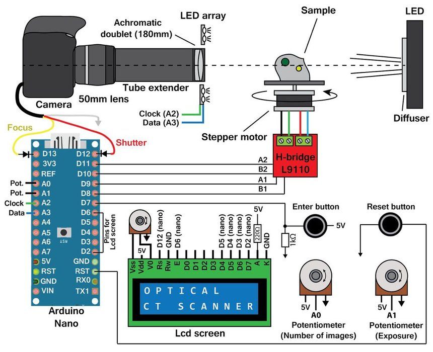 When the sensor circuit is closed on a digital pin operating in INPUT mode, the value HIGH (5V) appears. The sensor circuit closes when the sensor probe touches the scanned object. For the scanner to work, you will need a new firmware, which can be downloaded from the Firmware page. You also need a CNC machine control program of version 1.0.2 or higher, which can be downloaded on the Programs page.
Description of the operation of a 3D scanner based on Arduino
A grid is built over the working area, at the nodes of which the distance to the scanned object is measured using a sensor. Further, using the bicubic interpolation algorithm, the values of the distance to the object in the intervals between the lattice nodes are calculated. Now, having received all the necessary data, the program builds an image or a 3D model of the object. It is possible to upload the obtained values of the distances to the object in the lattice nodes to a separate file, which can later be used at the discretion of the user.