3D printing under extrusion
How to Fix Under-Extrusion in 3D Printers – Not Extruding Enough – 3D Printerly
A problem that I’ve experienced with my 3D printer is an inconsistent extrusion from the nozzle with a print, which looks bumpy. I wondered how to fix this problem, so I researched exactly how to fix a 3D printer that stopped extruding consistently and got some answers that I’ll share with you.
The best way to fix a 3D printer that is extruding inconsistently from the nozzle is to clear any clogs or jams in the extrusion system, whether that’s in the extruder gears, Bowden tube or nozzle. You should also make sure your filament spool can rotate freely and use a larger layer height.
There are other factors that contribute to your 3D printing extruding inconsistently, which will be explained further in this article.
Why Does My 3D Printer Stop Extruding Consistently?
Bad Filament Pathing or Tangled Filament
If the filament is wounded improperly or the threads are not rolled off by the 3D printer correctly, the filament can get stuck resulting in uneven extrusion.
When the filament spool gets jammed, it produces friction which usually loses its grip on the material when fed into the printer. This results in lower emissions through the reduced flow of the material.
If the filament spool is empty, you will have to load the spool before moving forward. If the spool is not empty, you should check that the filament can easily pass through the Bowden tube.
Check to see if there is much resistance and consider cleaning the tube or applying some lubricant in the pipe.
Extruder Motor Issues
The extruder motor is the most functioning component of the 3D printer. It pushes and pulls the plastic back and forth constantly.
This fast motion requires a current, and if the printer’s electronic components are not cooled enough, the extruder motor will be overheated.
In this case, the motor controllers usually have a thermal cutout which causes the controller to stop working until the temperature goes down. So turn off the printer for some time allowing components to cool down.
Slipping of the Extruder Gears
If your extruder gears have start to wear out over time, it can’t get the same grip that it needs on the filament to extrude it through smoothly. I would check on your extruder gears and look for noticeable blunt areas on the teeth.
A good dual-geared extruder or a fresh extruder should correct this easily.
Layer Height Too Low
The layer height has a significant impact on 3D printing. If you are trying to print something at a low layer height, there will be very little room for the plastic to come out of the nozzle. Make sure to use the appropriate layer height for the printer.
You can change the layer height directly in your slicer software which has different methods depending on your program, but it should be fairly easy to operate.
Increase your layer height gradually through trial and error, and you should be able to eliminate the problem of not extruding during the print if this is your cause.
Inaccurate Extrusion Width
Like the layer height, extrusion width can also cause problems. Different extruders have different extrusion width, so be sure to choose the right extruder and assign the right extrusion width to get a silky and smooth 3D print.
It becomes difficult for the printer to extract material if the width of the extrusion is significantly less than the diameter of the nozzle.
According to the manufacturers, the perfect extrusion width is 100% to 150% of the diameter of the nozzle. You should be able to find these in your slicer using the search function, or by expanding the basic/advanced level view of your settings.
Extruder Jammed or Clogged
If the printer is not extruding enough, the extruder may be clogged. If this happens, check that the filament is clean and the spool is dust-free. If there is a lot of dust on the reel, it can block the extruder as it accumulates inside the nozzle.
In some cases, the plastic isn’t extruding properly, so you can try extruding some plastic manually. If you are still facing issues, you may need to clean the nozzle by following the instructions provided in the video below by Thomas Sanladerer.
Bad Quality Filament
A filament of inadequate quality is one of the most common reasons that cause printers not to extrude enough. Bad quality filaments contain some additives or have unstable filament diameters that affect the consistency of the flowing plastic.
The filament of high quality includes a dryer in the packaging because PLA absorbs the moisture from the air and affects the quality of the printer.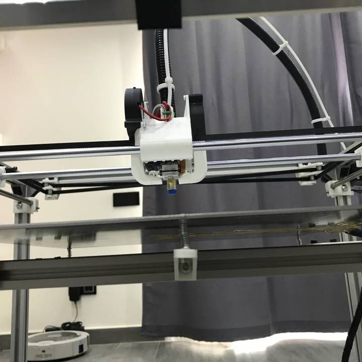 If you think this is the problem, try replacing the existing spool with a new, sealed spool of better quality.
If your PLA has absorbed moisture and starts popping while being heated to high temperatures, some people have fixed this by placing it in an oven at a low heat. You can also use a food dehydrator to do the same job.
Heat Creep Issues
Heat creep is a form of a blockage or clog within your extruder system. It occurs because of a temperature imbalance, where the heat actually travels a little further than it’s supposed to into the PTFE tube.
What then happens is filament because softer within the filament tube and starts to get pushed around the outer extrusion path, leading to extrusion problems.
This can occur if your PTFE tube has worn out, or you have a bad heatsink which doesn’t negate heat away from this area.
How to Fix Inconsistent Extruding From Nozzle?
Patience is something that you will need to consider 3D printing as a profession or hobby.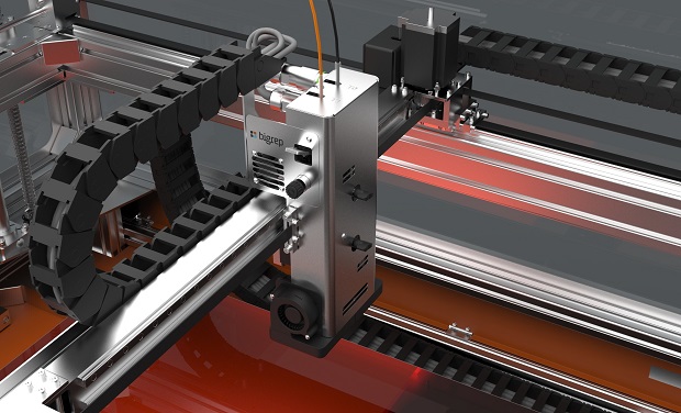 None of the solutions mentioned in this article is complicated. But you will need the patience to clean, remove, and fix the problem efficiently.
Once you find the cause of your inconsistent extrusion, the solutions becomes a lot easier to figure out as illustrated above.
The best intervention is to buy good quality filaments, make sure that the filaments and nozzles are clean, and review the best printer settings for your filament.
If you are experiencing under extrusion at a certain height, you want to check that your Bowden isn’t getting pinched at those higher heights. One thing you can do is to raise your Z-axis through the control box on your printer and see if there are any issues.
Installing a longer Bowden tube should fix this problem. The Creality Capricorn Bowden PTFE Tubing from Amazon is a good choice for your printer.
Increasing your printing temperature is another method that has worked for many users to fix under extrusion at a certain height, so I’d try raising your temperature to see if that helps.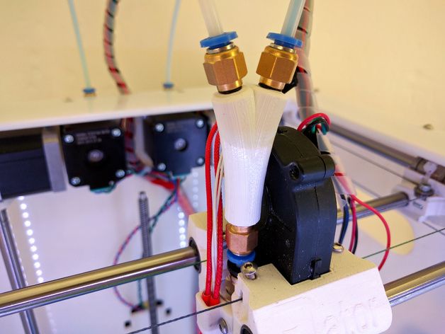
You may be experiencing under extrusion after a nozzle change, retraction, on small parts or even at the start of a layer. There are fixes for each of these specific with the right knowledge.
One of the main reasons why you experience under extrusion after a nozzle change is due to not tightening your nozzle against the heatbreak. If you end up leaving a small gap, you can start to have melted filament slowly leak out of this area.
I’d also make sure to clean out your extruder gears of dust and debris. Also, make sure you don’t over tighten the gears on your extruder, and you want it to be tight enough to have a fairly good grip.
If you are getting under extrusion after retractions, I’d try increasing the retraction length as well as adding some “Retraction Extra Prime Amount” in Cura or your chosen slicer to 0.25 – 0.5mm. Increasing this setting means you add more pressure in the nozzle chamber after a retraction.
It can take a little bit of testing, since larger values can results in blobs on your prints.
Sometimes people get under extrusion on small parts which can be a pain. For one user, the cause was through a badly wound spool of filament that was twisting and causing strong resistance in the Bowden tube. I’d check for the filament pathway and make sure things are going through smoothly.
In some cases, you may just have to change your nozzle to a fresh one, especially if you have never changed your nozzle and you use a brass one. With standard filament, brass nozzles can hold up pretty well, but after a few hundred hours of printing, or from scraping on the build plate, a change can be in order.
If you are getting under extrusion at the start of a layer, check that your “Retract at Layer Change” setting is unchecked as this can decrease the pressure in the nozzle chamber. I’d also try increasing your “Retraction Extra Prime Amount” to a value around 0.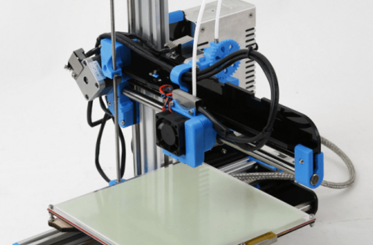 5 – 0.8mm.
Another solution for this issue that has worked for many users is to try turning “Combing Mode” off in Cura or your slicer.
How Can You Tell if a Nozzle is Clogged?
The most obvious symptom is that the filament does not come out of the nozzle properly. The filament is curling or sticking to the tip of the nozzle. There will be a sound or clicking from the extruder. The other signs include:
- The extrusion is looking inconsistent.
- A lot of dust around the extruder motor.
- The print is not silky or smooth.
- Dotted lines around the print.
- The printed parts are too fragile.
- The filament spool has stopped turning.
How Do You Fix a Clogged Nozzle?
When you have a clogged print nozzle, you can use a number of cleaning techniques to resolve the issue depending on the material that is causing the hassle.
The method always recommended by the experts is to use cleaning filaments regularly, but this method is only suitable for partially clogged nozzles and will not open the completely clogged issue. Below are some other techniques to fix a clogged nozzle.
- Use a brass wire brush to clean the dirt from the nozzle.
- Acetone is well known to dissolve thermoplastic. Cleaning the nozzle with an acetone bath helps to remove unwanted particles and will fix the clogged nozzle.
- The other way to fix a clogged nozzle of 3D Printer is to clear it using an acupuncture needle.
- Heat the nozzle to 250 degrees Celsius and insert the cleaning filament into the nozzle until the nozzle is completely free of old threads. Remove the filament and reheat the nozzle to remove tiny filament particles and then clean the nozzle thoroughly.
It’s usually easy to distinguish under extrusion vs over extrusion for your 3D printer. You’ll see that your 3D prints have more gaps and are generally weaker than usual if you have under extrusion.
Over extrusion is also clear to see, where you have plastic squashed together, leading to a low quality 3D print that isn’t very dimensionally accurate.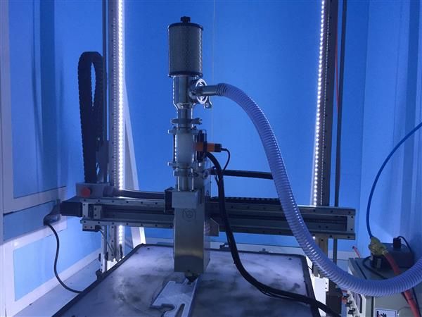 It is most visible in the outer dimensions of your 3D print.
How To Clean & Prevent 3D Printer Jams
There are various solutions to fix 3D printer jams, but the ideal solution is to prevent it from clogging. Below are the tips that will help you to clean and deter 3D printer jams in the future.
Thoroughly clean the nozzle when switching between filaments.
- Print at the right temperature to avoid electronic components overheat
- Use a clean filament of high quality
- Calibrate your printer bed at the right level
- Set an optimal and perfect layer height of 50% to 70% of the nozzle height, which is recommended by the experts.
- Try to store your spool in an airtight bag because this will not only prevent dust from accumulating but also prevents the absorption of the moisture from the air.
How to Avoid Under-Extrusion on a 3D Printer: Full Guide
- Author
- Recent Posts
Martin
Martin has a M. Sc. in physics and has gained many years of experience in industry as a lab manager and quality assurance manager. He has now tested dozens of 3D printers and is happy to share the collected experience with each new article.
Latest posts by Martin (see all)
Disclosure: Links marked with * are Affiliate Links. I earn from qualifying purchases if you decide to make a purchase through these links – at no additional cost for you!
If you’re a bit more experienced in 3D printing, you’ve already encountered some problems that needed to be fixed. With a technology as complex as 3D printing, it’s only natural that different things can cause difficulties or errors.
Often there is not only one solution to fix them. Finding the problem usually involves many small changes and adjustments, so it is much better to actually understand what the different settings on a 3D printer mean.
Under-extrusion is among the most frequent problems in 3D printing. Prints that have come out of the printer incorrectly due to under-extrusion are very easy to detect. With such models, you can detect too thin layers or those which are missing completly as well as random dots or holes. However, these prints are not only unsightly but also very weak in their structure.
But what exactly causes an under-extrusion and what settings do you need to adjust to fix this problem? The following article will give you answers to these questions.
What is under-extrusion?
As you can see from the name, under-extrusion occurs whenever not enough filament material is extruded from the nozzle. Such a shortage of material leads to irregular recesses within a layer or to layers that have not been printed or not printed strongly enough. While this problem is easy to identify, the problem-solving process is somewhat more complicated.
Under-Extrusion! (source: reddit)Table of Contents:
- 1 The Main Causes of Under-Extrusion
- 1.1 Bonded Filament Spools
- 1.2 Warped Teflon Tube
- 1.3 Too Little Pressure on the Filament Feed
- 1.
 4 Clogged Extruder
 - 1.5 Blocked Bozzle
- 1.6 Low Printing Temperature
- 1.7 Printing Speed too High
- 1.8 Problems of the Filament
- 2 Solutions for Under-Extrusion
- 2.1 Materials and Equipment
- 2.2 Adjusting the Printer Settings
- 2.3 Check the Internal Components
- 3 Inconsistent Extrusion
- 3.1 Solutions for Inconsistent Extrusion
- 4 Related Questions
- 4.1 How can an Under-Extrusion be Detected?
- 4.2 Why Should the Extruder of a 3D Printer be Calibrated Regularly?
- 4.3 What Happens During Over-Extrusion?
- 4.4 How Can Over-Extrusion be Solved?
The Main Causes of Under-Extrusion
Bonded Filament Spools
Filaments tend to get stuck if they are not coiled properly. Jamming can also occur if the filaments cannot be unwound properly from your 3D printer.
If the filament spool is stuck, this causes friction, which in turn often leads to a loss of grip on the motor when the material in question is fed into the printer. This circumstance ultimately leads to a reduced material flow and within a short time to under-extrusion.
Warped Teflon Tube
Many FDM printers work with tubes made out of Teflon to unwind the filament and guide the thread into the print head. If these tubes are bent or distorted in any way, they cause a lot of friction on the filament. This additional friction exerts strong pressure on the feed motors, which consequently leads to under-extrusion.
Among the distortions and warping in the Teflon tubes was overheating of the entire structure, since FDM printers emit a lot of heat. If you do not maintain your machine regularly or if it is overused very often, this can also have a negative effect on the Teflon tubes.
Too Little Pressure on the Filament Feed
Most FDM printers offer you the possibility to adjust the print settings for the filament feed. This pressure controls the force the motor exerts on the filament to keep a firm grip on the material.
If this pressure drops, the motor loses its grip on the printing materials, which in turn leads to under-extrusion.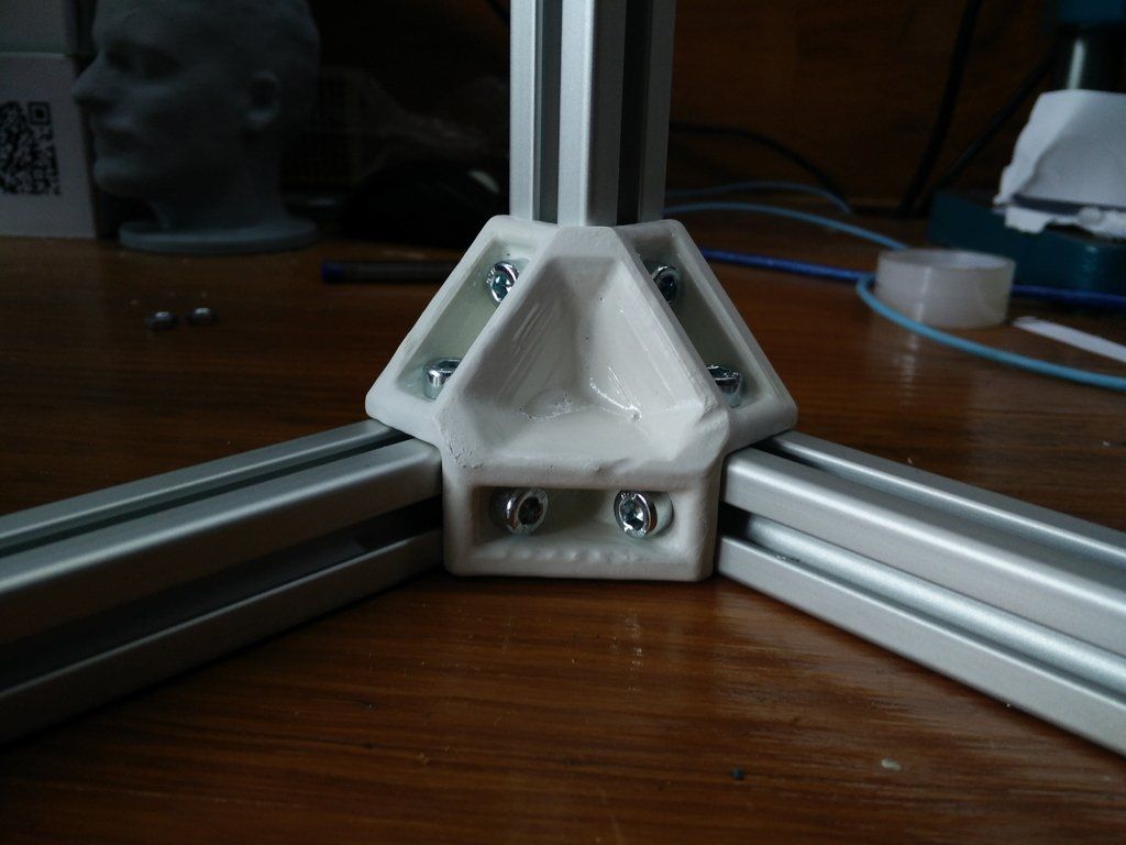 You can easily check the filament pressure by hand. To do this, you hold the filament down during the printing process while the motor is rotating.
If you feel the filament slipping, you should increase the pressure accordingly. It is also important that you adjust the feeder pressure each time you change the filament. There is a special diameter for each manufacturer.
Clogged Extruder
If there are stuck objects in the extruder head of your 3D printer, such as remnants of filament, the new filament thread introduced through it will receive additional friction when it reaches the nozzle. This additional friction slows down the printing material from reaching the nozzle, resulting in under-extrusion.
Another cause of blockage can be the feeder motor. Therefore make sure that the gear wheel of the feeder motor, which pushes the materials through the nozzle, is not contaminated with filament residues.
Blocked Bozzle
From time to time you should also clean the nozzle of your 3D printer.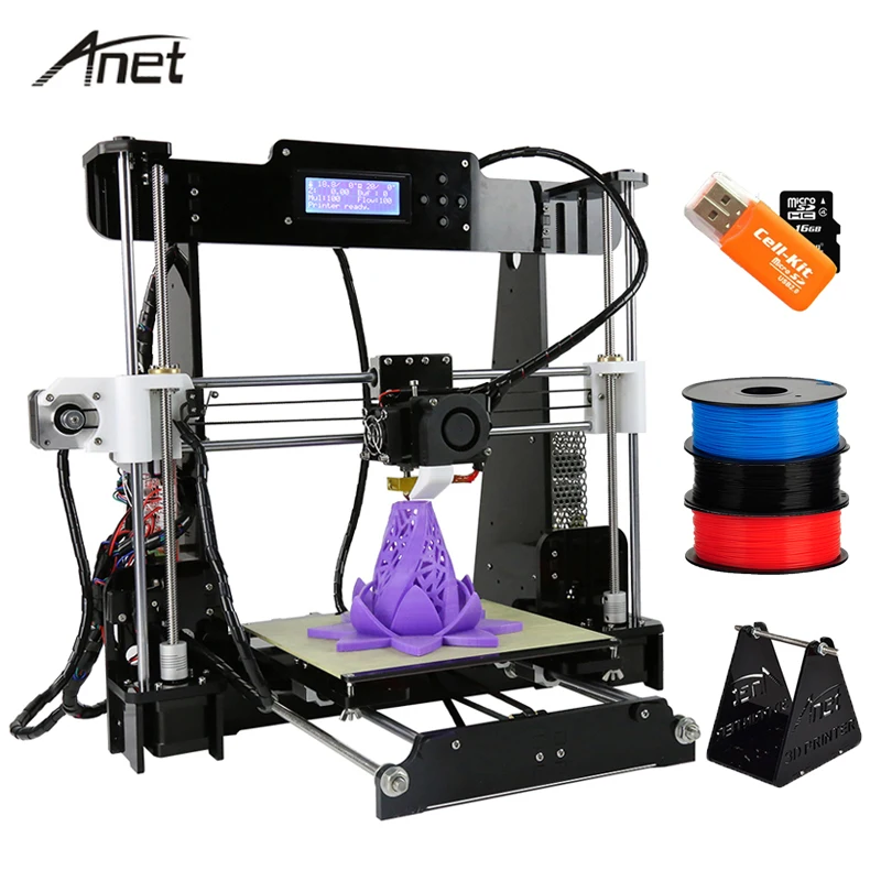 The residue and remnants of materials that pass through it can stick to the hole and block it.
A clogged nozzle is the most common cause of under-extrusion. To be on the safe side here, you can first carry out a small test: In the first step, take off the extruder lever and press the filament through by hand.
If it goes through with low resistance, the nozzle is clean. However, if you feel some resistance in the process while the filament is coming out or if this is not possible at all, the nozzle is clogged and you should clean yourself immediately.
Low Printing Temperature
Another of the most common causes of under-extrusion is a nozzle temperature that is set too low. If you press at high speed, the flow rate of the filament through the nozzle is increased.
However, if the nozzle cannot become hot enough, the filament will not melt properly and also not at a speed corresponding to the fresh material fed into the nozzle. This in turn has a negative effect on the filament flow and causes under-extrusion.
Printing Speed too High
Overly fast print speeds can also be the reason why you’re experiencing problems with your 3D printer. During the extrusion process, you must always make sure that the flow rate matches the print speed.
If the printing speed exceeds the flow rate, not enough material reaches the nozzle, resulting in under-extrusion. Considering this, it is advisable to change the printing speed so that it is synchronized with the feeder rate. Reduce the printing speed by 20 millimeters per second and then observe the result.
Problems of the Filament
In addition to the settings listed, it is also possible that the problem lies directly with the material itself. For example, after removal from the 3D printer, the filament may become tangled and stick before it can enter the feeder. It is therefore advisable to always check that the filament on the spool does not overlap before you start printing.
Another reason is the absorption of too much moisture by the filament.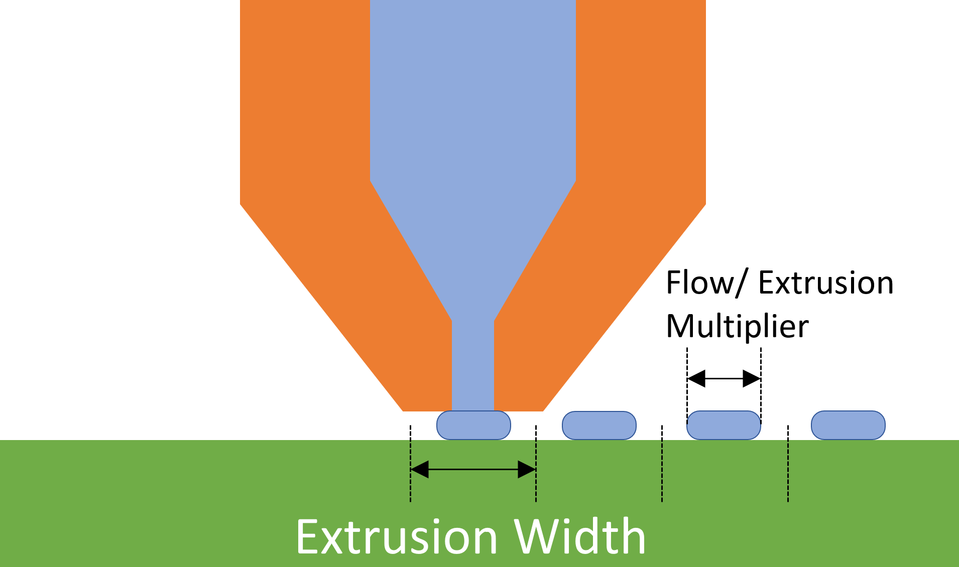 Some materials, such as PVA*, are very sensitive to moisture and can lose quality if used or stored in a humid environment for too long. The correct handling and storage of the material is therefore very important.
Solutions for Under-Extrusion
The difficulty in solving the problem of under-extrusion lies in the fact that there are so many possible reasons for its existence. 3D printers typically rely on the proper coordination of the extruder, hot end and print head to produce a high-quality print.
Any small bug in this sensitive system can cause problems, and in most cases, you will have to make several settings before you can fix them.
Below is an outline of the simplest and most basic steps to solving under-extrusion, along with an explanation of what other printer settings you can adjust on your 3D printer for this purpose.
Materials and Equipment
Checking the Filament Diameter
Even if this point seems obvious, mistakes are often made here. If you are using a filament with a diameter of three millimeters, but your slicer settings only have a diameter of 1.75 millimeters, your extruder will not run at a sufficient speed.
Even the smallest deviations in diameter are sufficient to cause problems with under-extrusion. This fact makes you realize once again how important it is to buy your filament from a high-quality and reliable supplier.
If you have a caliper, you should quickly check the diameter of your filament and make sure it is displayed correctly in your slicer software.
Check the Winding of Your Filament Spool
If your filament spool is properly wound, it is strong enough to ensure an even and continuous feed to the extruder. However, it is not so tight that the filament can get stuck in it.
A stuck filament causes significantly increased friction in its feed. Ultimately, this can cause the feeder to lose its grip on the material, which in turn reduces the filament flow to the extruder. If you often notice that the filament gets stuck, you should loosen it and rewind it manually.
Make sure that no overlapping sections are formed so that the filament can flow out freely and without problems.
Check the Teflon Tube for Deformations
Filaments must have a smooth and uninterrupted path from the spool to the extruder to ensure a constant feed rate to the nozzle. The majority of 3D printers today use Teflon tubes to reduce this friction.
However, these tubes can be damaged by frequent use or very high temperatures. Even the slightest deformation of the tube can slow down the entry of the material into the nozzle, resulting in under-extrusion. If the Teflon tube is damaged, you should replace it immediately or carry out your print jobs without it.
Adjusting the Printer Settings
Check the Performance of the Feeder
The feeder not only ensures that the filament is fed forward, it is one of the components, which can be a reason for under-extrusion if it is not working properly.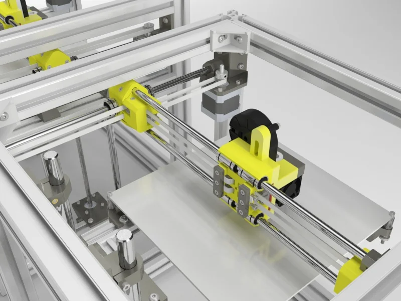
If you notice that the feeder does not move the filament to the extruder, you may need to increase the pressure on the feeder.
Adjusting the Print Temperature
If you set the printing temperature and speed wrong, you could get under-extrusion as well. Feeding the filament to the hot end of the nozzle at too high a speed may not expose it to enough heat to melt.
So make sure that the temperature is adjusted to your filament. However, you should not exceed the recommended range, otherwise some plastics will degrade if you set the temperature too high.
Setting the Extrusion Multiplier
Sometimes the problem with under-extrusion is that the extruder cannot press out the filament fast enough. In such a case you can try to increase the extrusion multiplier step by step by 2.5 percent.
Ensure that you do not cross the threshold where clogging is about to happen. It is also possible that you will have to set the temperature higher at the same time.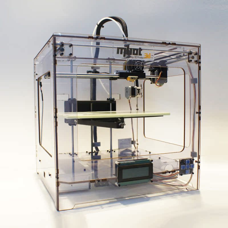
Check the Internal Components
Check the Nozzle for Possible Blockage
If you have already ruled out all the above-mentioned possibilities for under-extrusion, the problem may be due to the nozzle. You have several options to check your nozzle without disassembling it.
A blockage can already be removed, for example, with the help of a pen or by using the cold drawing method. In case you do not succeed with this, remove and carefully clean the nozzle.
If there is filament in the nozzle, you can try to put it in acetone to dissolve the blockage. If your nozzle is still blocked despite all attempts, you should buy a new one.
Checking the Extruder Roll
If you suspect that the under-extrusion is due to your extruder roll, you will have to disassemble it. Unfortunately, a faulty extruder always leads to extrusion problems.
The majority of extruders are equipped with two main parts that assist in transporting the filament to the nozzle at the hot end. These components are the tension roller and the drive wheel. The drive wheel is responsible for gripping the filament, while the tension roller gives a smooth surface against which the filament is held.
It is obvious that the idle speed is subject to much friction during the entire printing process. As a result, the tensioner pulley can wear out quickly, as it is normally made out of PTFE. If the tensioner pulley is too badly damaged, the entire extruder assembly will start to grip the filament, which in turn will lead to under-extrusion.
Check the Extruder Gear Head for Blockages
The other part of the extruder consists of a gear head. This is essentially a roller gear that is moved by the stepping motor. The gear wheel grips the filament and holds it against the tensioning roller. The filament is moved by the gear rotation, which moves it in measured steps towards the nozzle at the hot end.
A common problem is that filament chips accumulate in the gaps of the gear teeth and gets stuck in them. This decreases the gripping ability of the drive gear and causes under-extrusion.
First, try to push the filament manually into the extruder. To do this, open the machine control panel of your slicer software and heat your extruder to the temperature suitable for the plastic in question. Afterward, you extrude a small amount of plastic. While turning the extruder motor, you should carefully use your hands to push the filament into the extruder. Often this additional force is already sufficient to transport the filament beyond the problem area.
If the filament still does not move, you should unload it in a next step. Make sure that the extruder has been heated to the appropriate temperature and pull the filament out of the extruder using the mentioned machine control panel.
If the filament does not move, carefully help manually. Once the filament is removed, cut off the melted or damaged part of the material with scissors. Then reload the filament and check whether you can extrude with the new, undamaged filament section without any problems. If this is not possible, you must clean the nozzle thoroughly before you can continue.
For this purpose, it is recommended to first heat the extruder to 100 degrees Celsius and then carefully pull out the filament manually. In the best case, you will also get all the residues contained in the filament.
Inconsistent Extrusion
Under-extrusion is just one of the problems you have to solve as a 3D printing user. If you want your printer to produce precisely printed parts, it must be able to extrude a consistent amount of filament. If the extrusion is different on parts of your print model, it will influence the print result and quality.
You can usually detect an inconsistent extrusion by watching your 3D printer closely during the printing process. For example, if your device prints a straight line 20 millimeters long and you notice that the extrusion appears bumpy or varies in size, you are faced with an inconsistent extrusion. This can be an under-extrusion as well as an over-extrusion.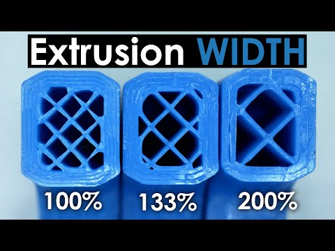
Solutions for Inconsistent Extrusion
In most cases, inconsistent extrusion is caused by the filament tangling up or getting stuck somewhere. The first thing to check in this case is the plastic spool that is fed into your printer.
This must be able to turn smoothly, the plastic must be able to be easily unwound from the coil. If the filament is entangled or if the spool is too resistant, it will negatively affect the extrusion of the filament.
If your printer has a Teflon tube, clean it or apply some lubricant to the tube.
If it is not the filament, check the nozzle yourself. If there is dirt or small residues in it, you should try to extrude some filament manually. If this causes problems, you should clean it carefully.
A clear sign of inconsistent extrusion is a very low layer height of your 3D printed model. If you have selected an extremely thin layer height of 0.01 millimeters, for example, very little plastic can escape from the nozzle. The gap under the nozzle is also only 0. 01 millimeters high. This means that it can be very difficult for the plastic to leave the extruder. Always make sure that you use a layer height that is appropriate for your printer.
It is also possible that the set extrusion width is responsible for the inconsistent extrusion. If the extrusion width is considerably smaller than the nozzle, problems during extrusion can occur. The extrusion width should always be within 100 to 150 percent of the diameter of the nozzle. If it is far below this, the extruder cannot promote a uniform filament flow.
Inconsistent extrusion is also caused by filaments of poor quality. If you use poor quality material, it will contain additional additives that affect the consistency of the plastic. An inconsistent filament diameter also leads to inconsistent extrusion. Filaments like PLA* absorb moisture from the surrounding air quickly. Because of this, they are often supplied with a desiccant to remove moisture.
If your filament is faulty, replace it with a new high-quality spool in an unopened package and see if this already solves your problem.
Related Questions
How can an Under-Extrusion be Detected?
Each profile in a slicer software contains settings that allow you to specify how much plastic to extrude from the 3D printer. However, because the device does not tell you how much filament will eventually come out of the nozzle, the actual amount may differ from what the software expects.
In such a case, gaps between the adjacent extrusions of each layer can be detected. This phenomenon is called under-extrusion. The surest way to determine whether the 3D printer is extruding enough plastic is to make a test print in the form of a 20-millimeter cube with at least three outlines. If the three perimeters in the upper part of the cube are strongly connected, extrusion is sufficient. If there are gaps between them, too little plastic is extruded.
Why Should the Extruder of a 3D Printer be Calibrated Regularly?
The calibration of the extruder is important for FDM 3D printing for several reasons. The background of extruder calibration is to determine whether or not the printer pushes exactly the right amount of filament through the hot end during a printing process.
Too little filament means that the print model has gaps between the layers or that these are too weak or missing completely. In addition, adhesion is insufficient and prints may be subject to layers that delaminate or warp.
If too much filament is extruded, over-extrusion may occur. This results in dents in the printed object, clothing or distortion. An extreme over-extrusion can even lead to blockages or filament jams at the hot end. For this reason, the extruder should be regularly calibrated on a 3D printer.
What Happens During Over-Extrusion?
Over-extrusion is when too much material is extruded from the nozzle of the 3D printer. This can negatively affect the quality of the printouts. This can result in dimensional inaccuracies, sagging layers, wet spots, smudges or even material jams. These signs usually indicate the presence of over-extrusion.
How Can Over-Extrusion be Solved?
In the case of over-extrusion, first, check the setting of the extrusion multiplier. This determines the speed at which the 3D printer extrudes the plastic. Most slicers have a default value of 1 or 100 percent. If the printer has unusually large layers or a jam in the nozzle, the extrusion multiplier is usually switched off. If the 3D printer is extruding too much material, this setting should be gradually reduced by 2.5 percent.
If the extrusion multiplier is not the problem, the printing temperature should be reduced in the next step. If this is too high, overmelting filament will occur, which exits uncontrolled from the nozzle of the device. The printing temperature should be reduced by five degrees Celsius in stages, depending on the filament, until the optimum temperature is reached for both the 3D printer and the material.
Another possible cause is an incorrect filament diameter entry. If a smaller filament diameter is stored in the slicer than is actually used, the extruder extrudes the filament at a higher speed, which in turn leads to over-extrusion. For this reason, the filament diameter should always be adapted to the material used.
Disclosure: This website is the property of Martin Lütkemeyer and is operated by Martin Lütkemeyer. Martin Lütkemeyer is a member of the Amazon Services LLC and other Affiliate Programs. These are affiliate advertising programs designed to enable websites to earn advertising revenue through advertising and linking to Amazon.com and others. Links marked with * are affiliate links.
Problem with extrusion? You are here / Habr
Do you know what a real universal fakap is? Recently, I fully felt it in my skin. I hope the text will be useful for novice 3D printers, since the problem is not an isolated one, but it was not easy to find a solution, and even I, an old atheist, almost believed in miracles. Forgive me for the presentation, since I am not a writer or a blogger, but a simple engineer - a firm engineer.
In addition, the text is intended for people with minimal experience with 3D printing.
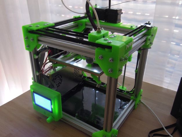
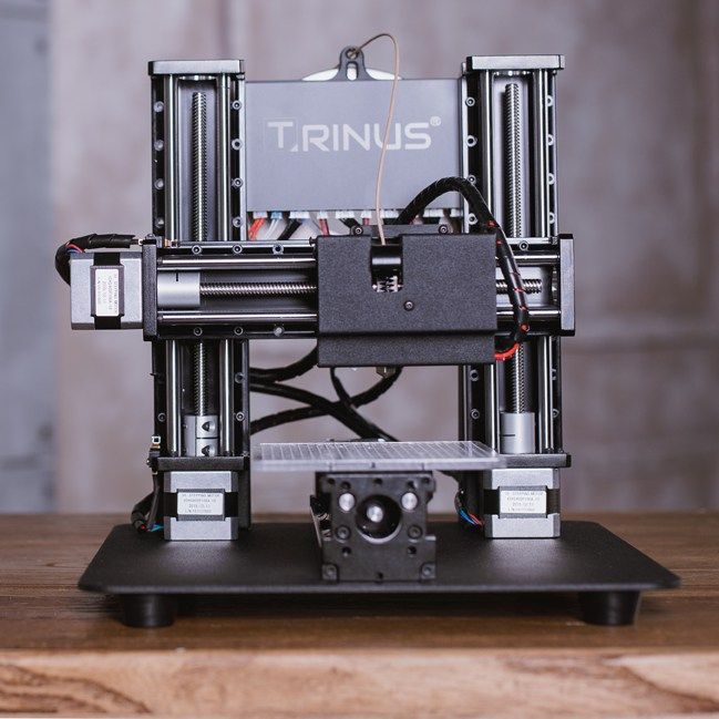
Solely for the reason not to inflate the article and not explain the purpose of various details and slang words. I'll start with the backstory. A little less than a year ago I bought myself an inexpensive 3D printer. One of the most popular (not as advertising, but to make it clear what it is about) is Ender 3. The assembly was simple, there are many recommendations on the Web. Of course, assembling it according to the instructions, I would have received a non-working unit, but after “smoking the manuals”, I managed to complete the first test print for 5 plus for such a simple machine! Everything was fine up to a certain point. But then it began ...
If you're interested, welcome.
For those who are too lazy to read:
The extruder pressure roller arm has broken.
The printer was needed for a specific task - printing non-standard cases for various small-scale electronic crafts. After I played enough with ready-made models and provided my daughter with various little animals and little men, I mastered FreeCAD “on top” and began to do useful things. Everything went well ... By and large, the print was launched "from the foot", set it and went to bed. Unless the first layer controlled. But the first "bells" appeared.
Somewhere part of the layer will fall out, somewhere the plastic will burn. I calibrated the table “according to a piece of paper”, sinned on the plastic and the nozzle, changed the settings in the slicer, plastics and nozzles - the problems disappeared. Bye…
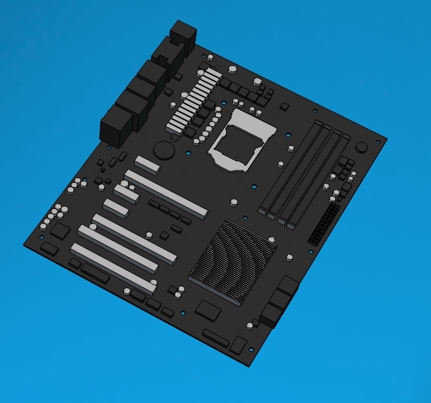
At one "wonderful" moment, I ran into an "insoluble" problem. The end of March, a smooth transfer to a remote location (I successfully moved from the Moscow region to Minsk 2 years earlier), I decided to assemble a separate computer for work from what I had. In the stash was a good motherboard, processor, a couple of monitors and 2 cases. One is a huge full-fledged ATX, the other is a barebone. I decided to collect in a small one, so that it takes up less space. The case is non-standard. With cradle for 1 CD drive and 3.5 inch hard drive. I found 3x 2.5 SATA SSD of small volume, for the system and one is enough "more than" and 1x for 1Tb 2.5 HDD.
All this "living creatures" was placed in a large building on a makeshift adapter from old bank cards. But, since a printer has already appeared, it would be nice to use it. I created a holder model, put it on print and went about my business. When I looked at how it prints, I saw only noodles ... From that moment on, the path of repair went, 2 months long. I will try to paint on the shelves, what helped and what did not, and what was the root cause.
Step 1 Adjusting the rollers {prevention is always good}
Once again, I set up the table “on a piece of paper”, launched it - the plastic does not stick. I changed the settings, plastics - without result. Instead of sticking to the table, it bends onto the nozzle. When I rechecked the nozzle gap settings, I found that the rollers were loose and the table had play by almost 5mm at the edges. It's strange how he used to print at all before ... It seemed that the reason was found. Adjusted. But it didn't get any better. With grief in half I printed the part, but the quality left much to be desired:
Obvious gaps in print are visible.
And here are the bundles…
Step 2. Song of Ze[l]de {not bad when everything goes like clockwork}
The first thing that came to my mind was the problem in the Z-axis drive. And all the advice on the forums on a problem similar to mine pointed to this. Took it apart and checked for smoothness. The nut bit the thread a little and found a “bug” in a couple of rollers. When moving without the drive screw, the "X" rail stuck a little for 1 turn of the roller. I ordered a drive nut, rollers (spare parts are always good, but that was not the point). Using the method of combinatorics and some kind of mother, I distributed the axle rollers according to the loads so that the defective ones had minimal effort. The "bite" is gone. Cleaned and lubricated the drive screw. Adjusted the position of his engine. As a result, a light touch of a finger is enough to lower the carriage down. The result is negative.
Step 3. Slicer {tuning, but not solving the problem}
Updated slicer. Moreover, the new release just had an improvement related specifically to the print quality for my printer. Played around with flow and speed, layer thicknesses, etc. Even successfully printed some simple small cases and parts. But the settings were frankly wild: flow - + 10%, speed - -5%. Considering that after assembly, excellent printing was obtained at the “default” settings. The problem of printing complex parts has not disappeared . ..
..
Based on this article: https://habr.com/ru/post/494058/ I made a brushing timer for my daughter. I am preparing a separate description for it. Spoiler: eight-legged controller, firmware - 119 assembler commands.
Step 3. Extruder {and happiness was so close...}
Logic dictates that since there are no problems with the geometry and drives of the axes, there must be something with the feed. Removed the filament feed gear and cleaned it. No visible wear is observed. I returned it to its place, slightly shifting along the flight, to even out wear. The result is 0. Eh, if I look a little to the right, I would save a month of nerves and $ 200.
Step 4. Checking the SD drivers {no comment}
Excellent geometry, no problems with the mechanics. At the time of the first assembly, everything was much worse. A bunch of studied materials, improvements and settings, and the result is zero. I do not believe in miracles, electronics remained. Moreover, members of the forum often complain about burnt drivers. It is clear that a completely burnt out shoulder of the bridge can be detected “by eye” immediately, I thought about a “floating” malfunction. After all, the plastic lays down normally, then - passes, the thread becomes thinner, hair and other charms. I ordered an improved control board on ARM, but in order not to waste time, I decided to check the existing one. I removed the board, the Z-axis motor as an inductive load, assembled the stand on the table, set the temperature of the hot end with a resistor so that the extruder could be rotated. I looked at the waveforms on the SD coils. Everything is great. He warmed the driver with a hairdryer (a crystal defect or unwelding sometimes manifests itself), mechanically acted on the driver IC, cooled propane with butane (gas for lighters). Note. It cools quite well to -20, it is not necessary to buy an expensive freezer for this.
 Everything is great. Failures are not visible!
Step 5. Updating the firmware {and I almost believed in a miracle and conspiracy theory}
No, I am sure that miracles do not happen. There are bugs, glitches, tricks, lack of information, subjective perception of reality, after all. But not miracles! But how to explain that, with good mechanics and electronics, printing behaves extremely strangely? The Chinese made a bookmark in FW in order to additionally barry with boards? It is done elementarily, but, I think, they would have been discovered long ago and a white fluffy fox would have come to the trademark. Bug in the firmware? Everything is possible, only somehow it manifested itself strangely.
EEPROM settings wrong or FLASH* "bugging"? Most likely. Okay, since the board is on the table, nothing prevents it from being reflashed. Updated to "vanilla" Marlin 1.1.9, collected everything back. The result is that the miracle did not happen.
*Purely theoretical substantiation of the possibility of connection of the problem with FLASH memory:
Let's say we have the following code fragment:
…
const uint8_t step = 0x18;
…
position += step;
…
At each iteration, the “step” setting is added to the current position. Since the program is executed on a microcontroller (MK), the code and constants are placed in ROM and can only be changed during an external programming procedure (we will omit the possibility of reprogramming the FLASH memory by internal means of the MK). This procedure is performed once by the manufacturer. Now 2 important points: the controller processor reads commands and constants from ROM every time, forget about caches, Atmega does not have them. That is, if the loop went through 1000000 iterations, then the constant was read the same million times. With each read, FLASH degrades a little. I don’t know what the critical reading threshold for NOR is, I think it’s tens of billions, but TLC NAND already degrades quite well after 10-20K readings . .. The second point is not the fact that our narrow-eyed friends did not use rejected controllers. I actually got one like this. PICs. Not soldered, but there are strange marks on the case. FLASH was not erased, at 3.6V they did not want to be erased or flashed. I had to raise it to 5V, after which the recording / verification began to take place. Let's say our constant was written to a defective cell. While the device is new, 0x18 was read stably. But from time to time (and for Atmega, the guaranteed time for saving data is not the longest) and degradation, at some point it began to read not 0x18, but 0x08. Not every time, but still. I know, rather than degrading 1 to 0, but vice versa, this is just an example. So, as long as the correct number is read stably, the movement occurs correctly, but when failures occur, an incorrect setpoint is added to the result, which leads to feed failures. This is the simplest and most unlikely example. There may be other glitches, for example, in the addition command, the source of R6 will change to R7.
 The assembler instruction remains valid, the processor will execute it, but the result will be incorrect ...
Step 6. Flush the “throat” {keep your head cool and the hot end clean, I recommend doing this immediately after buying a printer}
A gift from "heaven" was a link on one of the forums to a video from the manufacturer. There they honestly admit that not all hotends are equally useful, that is, they are well assembled.
Teflon tube not fully pressed in, cut uneven. The consequence is the formation of a cork and the extruder cannot normally advance the plastic. Here it is - my case!
Abnormal flow and retract values, everything converges. Despite late Saturday evening and a visit to a brasserie, I decided to check it out. Exactly. Guana is unmeasured there, right down to the remnants of the plastic that I used to print a month ago (the same green holder). Very likely to win! I cleared the “throat”, cut the tube evenly, pressed it in as far as it would go, also fixed the second end of the tube more tightly, many people use electrical tape, but I wound a little 0.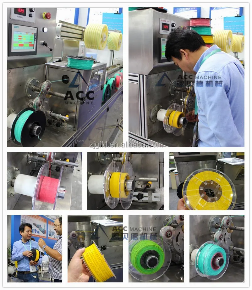 7 wire, which allows you to freely unscrew the holder:
And here is the “killed” end of the tube, you can see that it was cut crooked:
The model is cut into layers with default settings. The seal ... The border went, the contour went, there is no snot during the retract. Hooray!!! Victory!!! I was about to write an article so that others would not suffer, but ... A complete fiasco. Thinning and tearing of plastic, gaps in printing. Already ready to give up. The wife encourages, but you throw it away, buy a new one! I can't do that. There must be a reason. That's just where??? There were no more reasonable (and censored) thoughts ...
Remark about cleaning the “throat”:
All operations with the hot end are done only “hot”, otherwise there is a chance to break everything. After warming up, the first step is to remove the nozzle and clean it from the remnants of the “cork”. I did this by heating the nozzle on a gas stove flame and carefully removing the plastic.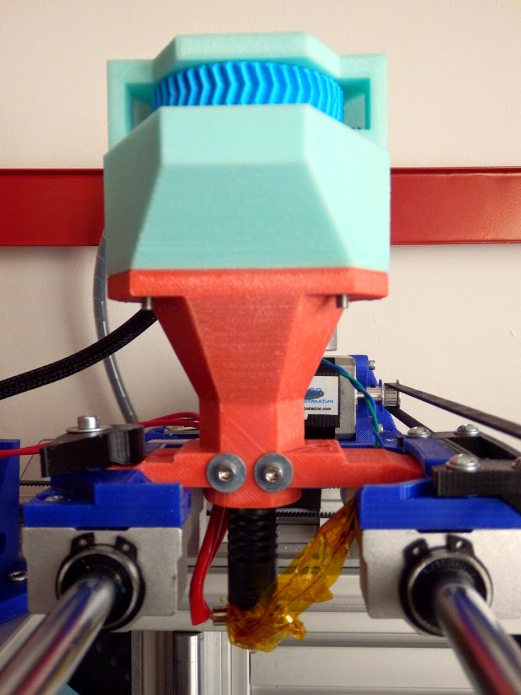 Didn't clean the inside. Then, also on a heated hot end, the tube clamp is unscrewed. He can only move up. After retracting the latch, the tube should be gently but with force removed from the “throat”. We remove all the latches, since the damaged end still cannot be saved, carefully, back and forth, we clean out all the dirt, constantly removing it from the tube. As a result, the tube should easily pass through the throat through and through. The assembly was performed by the FIFO sequence. First, I installed the nozzle, then the tube clamp in the hot end, but did not tighten it completely, leaving about 1 turn. The worn part of the tube is cut off at a right angle and inserted into the throat as far as it will go. After that, the holder is tightened and the second one is installed, on the opposite side of the "teflon".
Step 7. Feed Calibration {with good mechanics, most likely not needed unless after replacement of drive parts or flashing}
In the instructions for upgrading to the "vanilla" Marlin, it was said that for the factory printer all settings are ideal, but the accuracy of the plastic feed may be slightly off.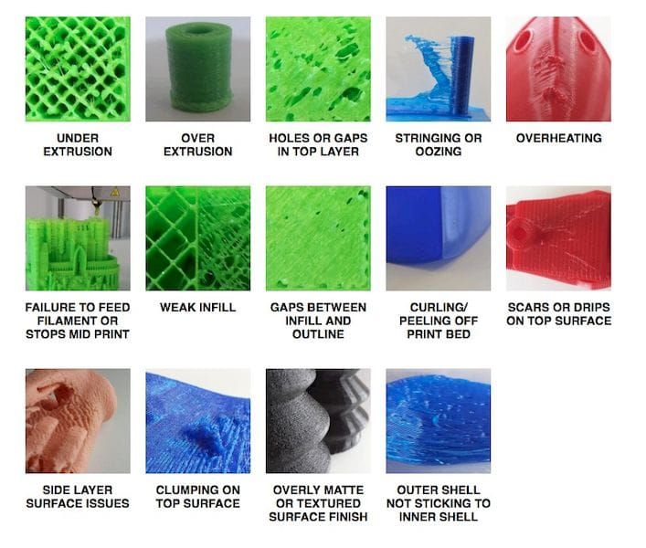 Okay, let's calibrate. He pulled out the plastic, warmed up the hot end (there is a lock in the firmware, it does not allow you to move “E” to a cold one). I unscrewed the tube from the feed mechanism, cut the plastic flush and executed the 300mm extrusion command. I have a ruler at 350. Extrusion lasts long enough, upon completion, I measured the length of the released filament and could not believe my eyes 226mm. I understand the difference of 3-5%, but not 25%! I'll try another plastic...
Note. I saw how the feed is regulated according to the marks on the bar marked with a marker, But with cutting, IHMO, more precisely.
Preparation for test extrusion:
After extrusion:
We measure with a ruler, in my case (after repair) it turned out 292mm. Next, go to the menu: control / motion / step mm, see how many steps per mm are set for the extruder. In my case it is 93. Let's do a simple calculation:
>>> (300*93)/292
95.54794520547945
Change the setting and save the setting. Re-extrusion - error at the measurement level.
Step 8. Victory!
At first I checked for PETG, I decided to change to PLA. The first one I overheated a little during drying, I attributed the inadequate spread to possible sticking on the coil. Cutting, extrusion. And nothing. Plastic is not supplied at all. The axis of the drive rotates slowly, but the screws show that there is movement. I looked, the bar did not lie correctly between the gear and the pressure roller. Okay, I'm correct. That the roller dangles a little. Gotta pull it up. And fig! Here he is the culprit of all my troubles:
The pressure roller arm is cracked. At the same time, the clamping force remained sufficient for partial advancement of the rod. Gear marks remained and the pressure roller rotated.
Accordingly, all games with the pressure spring setting were unsuccessful. The slips of the bar were invisible to the eye, and the crack could not be seen on the assembled mechanism.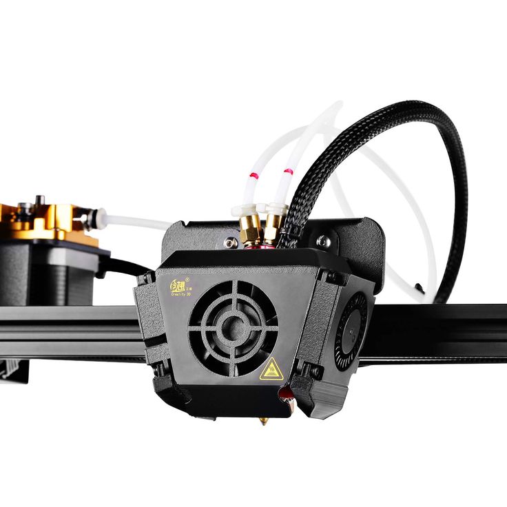 All! Engineer's ecstasy received! The lever was glued together, an aluminum mechanism was ordered, a spare was printed just in case (if it breaks while I wait for a new one). Here is a link to the model. Of course, it’s unpleasant to spend so much time and money over such a trifle, but it helped me dive much deeper into the processes of printing and catching glitches.
Actually, the first part after repair. Clamping lever:
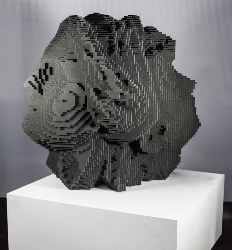
Finally, my presence sensor found a "face". The case was printed even before the breakdown:
Attempts to print a “face” on a faulty printer (after cleaning the “throat”):
I hope this material will help at least someone not to make so many stupid attempts to find a primitive malfunction and save money. Of course, I did not deal with the problem every evening, but in total - a day, probably, was spent. For the money - about $ 200 for parts. The price of troubleshooting is 15 minutes and a couple of drops of "superglue". It's a shame? Rather not, because the experience and spare parts will remain with me!
Smooth printing and excellent adhesion everyone!
3D printing for "dummies" or "what is a 3D printer?"
- 1 3D printing term
- 2 3D printing methods
- 2.1 Extrusion printing
- 2.2 Melting, sintering or gluing
- 2.3 Stereolithography
- 2.4 Lamination
- 3 Fused Deposition Printing (FDM)
- 3.1 Consumables
- 3.2 Extruder
- 3.3 Working platform
- 3.4 Positioners
- 3.5 Control
- 3.6 Varieties of FDM printers
- 4 Laser Stereolithography (SLA)
- 4.1 Lasers and projectors
- 4.2 Cuvette and resin
- 4.3 Types of stereolithographic printers
The term 3D printing
The term 3D printing has several synonyms, one of which quite briefly and accurately characterizes the essence of the process - "additive manufacturing", that is, production by adding material. The term was not coined by chance, because this is the main difference between multiple 3D printing technologies and the usual methods of industrial production, which in turn received the name "subtractive technologies", that is, "subtractive". If during milling, grinding, cutting and other similar procedures, excess material is removed from the workpiece, then in the case of additive manufacturing, material is gradually added until a solid model is obtained.
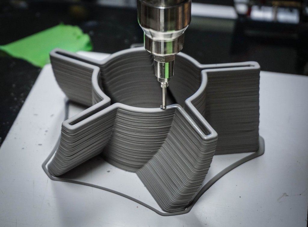
Soon 3D printing will even be tested on the International Space Station
Strictly speaking, many traditional methods could be classified as "additive" in the broad sense of the word - for example, casting or riveting. However, it should be borne in mind that in these cases, either the consumption of materials is required for the manufacture of specific tools used in the production of specific parts (as in the case of casting), or the whole process is reduced to joining ready-made parts (welding, riveting, etc. ). In order for the technology to be classified as “3D printing”, the final product must be built from raw materials, not blanks, and the formation of objects must be arbitrary - that is, without the use of forms. The latter means that additive manufacturing requires a software component. Roughly speaking, additive manufacturing requires computer control so that the shape of final products can be determined by building digital models. It was this factor that delayed the widespread adoption of 3D printing until the moment when numerical control and 3D design became widely available and highly productive.
3D printing techniques
3D printing technologies are numerous, and there are even more names for them due to patent restrictions. However, you can try to divide technologies into main areas:
Extrusion printing
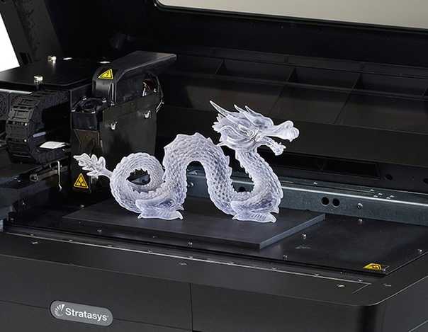
This includes methods such as deposition fusion (FDM) and multi-jet printing (MJM). This method is based on the extrusion (extrusion) of consumables with the sequential formation of the finished product. As a rule, consumables consist of thermoplastics or composite materials based on them.
Melting, sintering or bonding
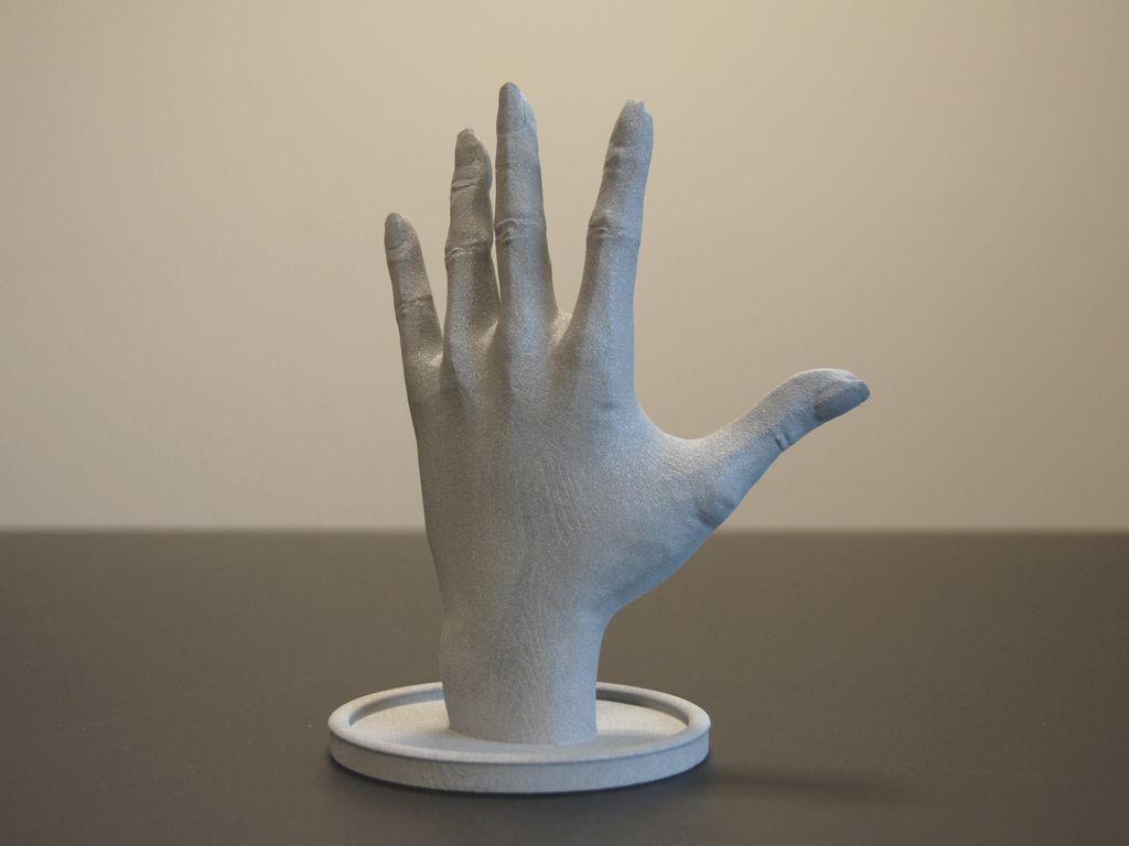
This approach is based on bonding powdered material together. Formation is done in different ways. The simplest is gluing, as is the case with 3D inkjet printing (3DP). Such printers deposit thin layers of powder onto the build platform, which are then selectively bonded with a binder. Powders can be made up of virtually any material that can be ground to a powder—plastic, wood, metal.
This model of James Bond's Aston Martin was successfully printed on a Voxeljet SLS printer and blown up just as successfully during the filming of Skyfall instead of the expensive original
sintering (SLS and DMLS) and smelting (SLM), which allow you to create all-metal parts. As with 3D inkjet printing, these devices apply thin layers of powder, but the material is not glued together, but sintered or melted using a laser.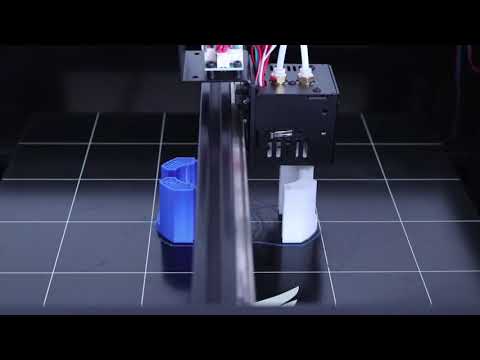 Laser sintering (SLS) is used to work with both plastic and metal powders, although metal pellets usually have a more fusible shell, and after printing they are additionally sintered in special ovens. DMLS is a variant of SLS installations with more powerful lasers that allow sintering metal powders directly without additives. SLM printers provide not just sintering of particles, but their complete melting, which allows you to create monolithic models that do not suffer from the relative fragility caused by the porosity of the structure. As a rule, printers for working with metal powders are equipped with vacuum working chambers, or they replace air with inert gases. Such a complication of the design is caused by the need to work with metals and alloys subject to oxidation - for example, with titanium.
Stereolithography
How an SLA printer works
Stereolithography printers use special liquid materials called "photopolymer resins".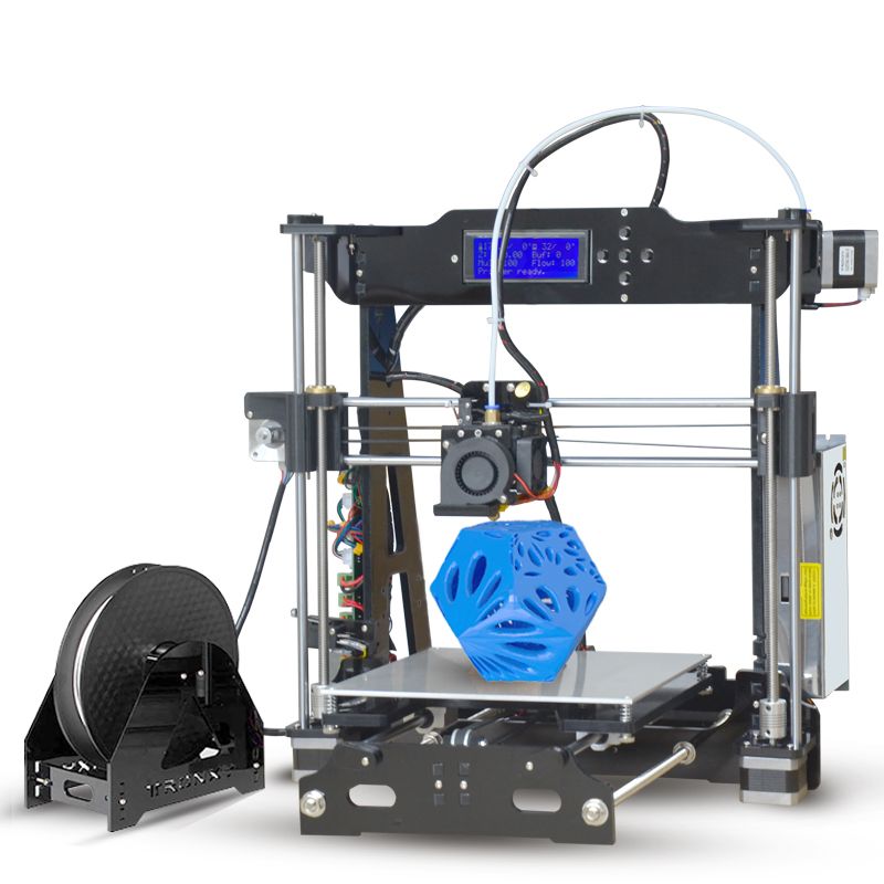 The term "photopolymerization" refers to the ability of a material to harden when exposed to light. As a rule, such materials react to ultraviolet irradiation.
Resin is poured into a special container with a movable platform, which is installed in a position near the surface of the liquid. The layer of resin covering the platform corresponds to one layer of the digital model. Then a thin layer of resin is processed by a laser beam, hardening at the points of contact. At the end of illumination, the platform together with the finished layer is immersed to the thickness of the next layer, and illumination is performed again.
Lamination
3D printers using lamination technology (LOM)
Some 3D printers build models using sheet materials - paper, foil, plastic film.
Layers of material are glued on top of each other and cut along the contours of the digital model using a laser or a blade.
These machines are well suited for prototyping and can use very cheap consumables, including regular office paper.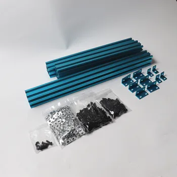 However, the complexity and noise of these printers, coupled with the limitations of the models they produce, limit their popularity.
Fused deposition modeling (FDM) and laser stereolithography (SLA) have become the most popular 3D printing methods used in the home and office.
Let's take a closer look at these technologies.
Fused Deposition Printing (FDM)
FDM is perhaps the simplest and most affordable 3D construction method, which makes it very popular.
High demand for FDM printers is driving device and consumable prices down rapidly, along with technology advances towards ease of use and improved reliability.
Consumables
ABS filament spool and finished model
FDM printers are designed to print with thermoplastics, which are usually supplied as thin filaments wound on spools. The range of "clean" plastics is very wide. One of the most popular materials is polylactide or "PLA plastic".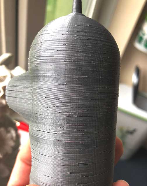 This material is made from corn or sugar cane, which makes it non-toxic and environmentally friendly, but makes it relatively short-lived. ABS plastic, on the other hand, is very durable and wear-resistant, although it is susceptible to direct sunlight and can release small amounts of harmful fumes when heated. Many plastic items that we use on a daily basis are made from this material: housings for household appliances, plumbing fixtures, plastic cards, toys, etc.
In addition to PLA and ABS, printing is possible with nylon, polycarbonate, polyethylene and many other thermoplastics that are widely used in modern industry. More exotic materials are also possible, such as polyvinyl alcohol, known as "PVA plastic". This material dissolves in water, which makes it very useful for printing complex geometric patterns. But more on that below.
Model made from Laywoo-D3. Changing the extrusion temperature allows you to achieve different shades and simulate annual rings
It is not necessary to print with homogeneous plastics. It is also possible to use composite materials imitating wood, metals, stone. Such materials use all the same thermoplastics, but with impurities of non-plastic materials.
So, Laywoo-D3 consists partly of natural wood dust, which allows you to print "wooden" products, including furniture.
The material called BronzeFill is filled with real bronze, and models made from it can be ground and polished, achieving a high similarity to products made from pure bronze.
One has only to remember that thermoplastics serve as a binding element in composite materials - they determine the thresholds of strength, thermal stability and other physical and chemical properties of finished models.
Extruder
Extruder - FDM print head. Strictly speaking, this is not entirely true, because the head consists of several parts, of which only the feed mechanism is directly "extruder". However, by tradition, the term "extruder" is commonly used as a synonym for the entire print assembly.
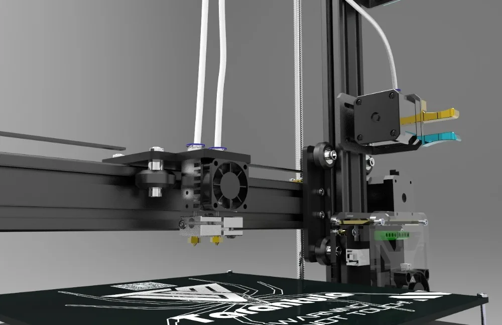
FDM extruder general design
The extruder is designed for melting and applying thermoplastic thread. The first component is the thread feed mechanism, which consists of rollers and gears driven by an electric motor. The mechanism feeds the thread into a special heated metal tube with a small diameter nozzle, called a "hot end" or simply a "nozzle". The same mechanism is used to remove the thread if a change of material is needed.
The hot end is used to heat and melt the thread fed by the puller. As a rule, nozzles are made from brass or aluminum, although more heat-resistant, but also more expensive materials can be used. For printing with the most popular plastics, a brass nozzle is quite enough. The “nozzle” itself is attached to the end of the tube with a threaded connection and can be replaced with a new one in case of wear or if a change in diameter is necessary. The nozzle diameter determines the thickness of the molten filament and, as a result, affects the print resolution. The heating of the hot end is controlled by a thermistor. Temperature control is very important, because when the material is overheated, pyrolysis can occur, that is, the decomposition of plastic, which contributes both to the loss of the properties of the material itself and to clogging of the nozzle.
PrintBox3D One FDM Extruder
To prevent the filament from melting too early, the top of the hot end is cooled by heatsinks and fans. This point is of great importance, since thermoplastics that pass the glass transition temperature significantly expand in volume and increase the friction of the material with the walls of the hot end. If the length of such a section is too long, the pulling mechanism may not have enough strength to push the thread.
The number of extruders may vary depending on the purpose of the 3D printer. The simplest options use a single print head. The dual extruder greatly expands the capabilities of the device, allowing you to print one model in two different colors, as well as using different materials. The last point is important when building complex models with overhanging structural elements: FDM printers cannot print “over the air”, since the applied layers require support. In the case of hinged elements, temporary support structures have to be printed, which are removed after printing is completed. The removal process is fraught with damage to the model itself and requires accuracy. In addition, if the model has a complex structure with internal cavities that are difficult to access, building conventional supports may not be practical due to the difficulty in removing excess material.
Finished model with PVA supports (white) before and after washing
In such cases, the same water-soluble polyvinyl alcohol (PVA) comes in handy. Using a dual extruder, you can build a model from waterproof thermoplastic using PVA to create supports.
After printing, PVA can be simply dissolved in water and a complex product of perfect quality can be obtained.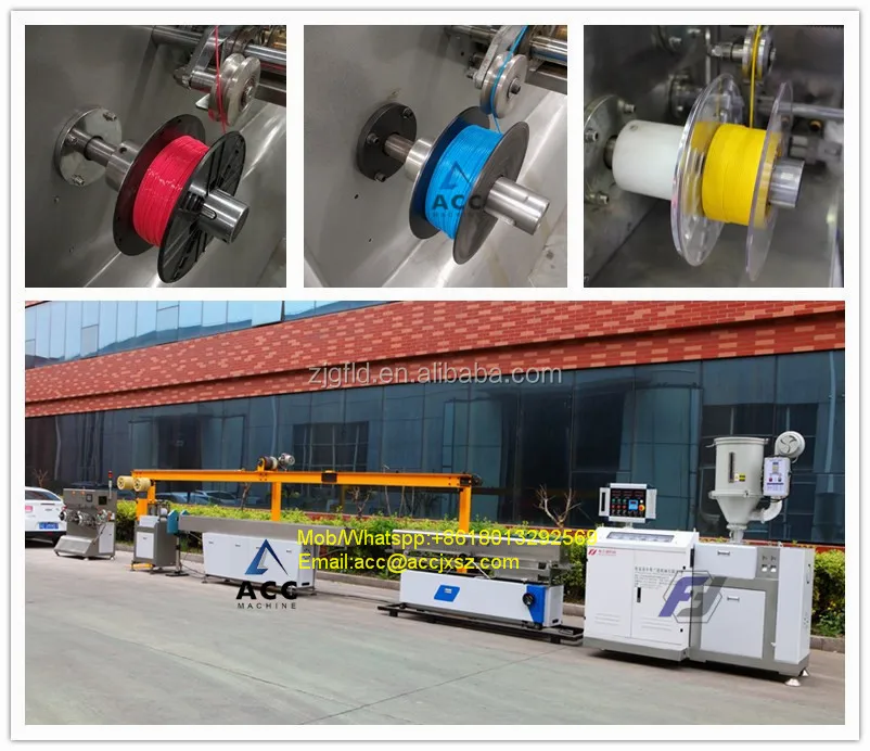
Some FDM printers can use three or even four extruders.
Working platform
Heated platform covered with removable glass work table
Models are built on a special platform, often equipped with heating elements. Preheating is required for a wide range of plastics, including the popular ABS, which are subject to a high degree of shrinkage when cooled. The rapid loss of volume by cold coats compared to freshly applied material can lead to model distortion or delamination. The heating of the platform makes it possible to significantly equalize the temperature gradient between the upper and lower layers.
Heating is not recommended for some materials. A typical example is PLA plastic, which requires a fairly long time to harden. Heating PLA can lead to deformation of the lower layers under the weight of the upper ones. When working with PLA, measures are usually taken not to heat up, but to cool the model.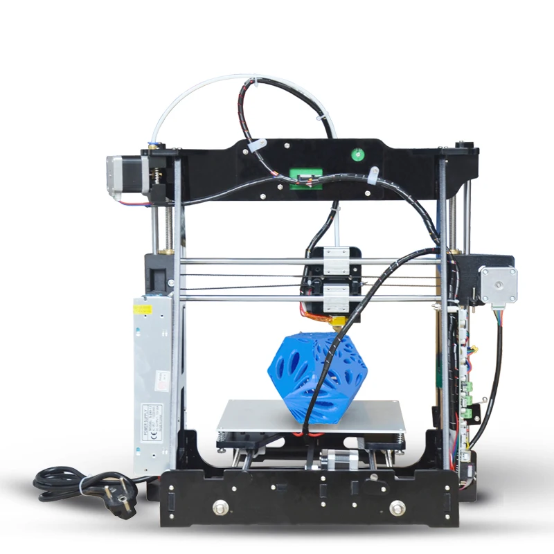 Such printers have characteristic open cases and additional fans blowing fresh layers of the model.
Calibration screw for work platform covered with blue masking tape
The platform needs to be calibrated before printing to ensure that the nozzle doesn't hit the applied layers and move too far causing air-to-air printing resulting in plastic vermicelli. The calibration process can be either manual or automatic. In manual mode, calibration is performed by positioning the nozzle at different points on the platform and adjusting the platform inclination using the support screws to achieve the optimal distance between the surface and the nozzle.
As a rule, platforms are equipped with an additional element - a removable table. This design simplifies the cleaning of the working surface and facilitates the removal of the finished model. Stages are made from various materials, including aluminum, acrylic, glass, etc. The choice of material for the manufacture of the stage depends on the presence of heating and consumables for which the printer is optimized.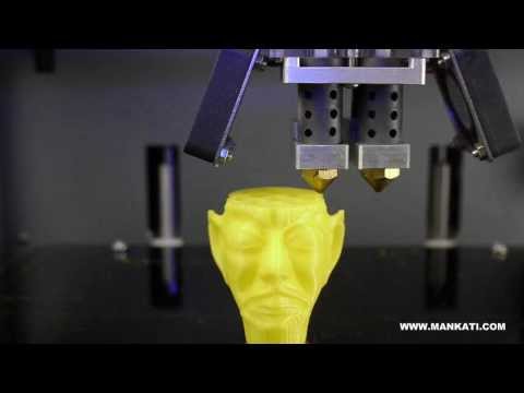
For a better adhesion of the first layer of the model to the surface of the table, additional tools are often used, including polyimide film, glue and even hairspray! But the most popular tool is inexpensive, but effective masking tape. Some manufacturers make perforated tables that hold the model well but are difficult to clean. In general, the expediency of applying additional funds to the table depends on the consumable material and the material of the table itself.
Positioning mechanisms
Positioning mechanisms
Of course, the print head must move relative to the working platform, and unlike conventional office printers, positioning must be done not in two, but in three planes, including height adjustment.
Positioning pattern may vary. The simplest and most common option involves mounting the print head on perpendicular guides driven by stepper motors and providing positioning along the X and Y axes.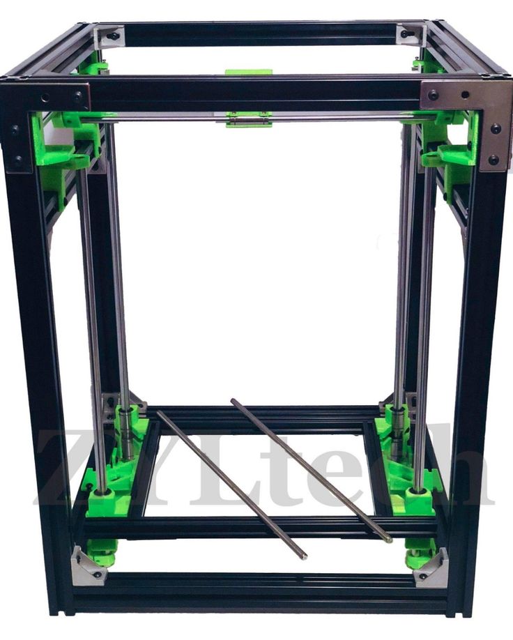
Vertical positioning is carried out by moving the working platform.
On the other hand, it is possible to move the extruder in one plane and the platforms in two.
SeemeCNC ORION Delta Printer
One option that is gaining popularity is the delta coordinate system.
Such devices are called "delta robots" in the industry.
In delta printers, the print head is suspended on three manipulators, each of which moves along a vertical rail.
The synchronous symmetrical movement of the manipulators allows you to change the height of the extruder above the platform, and the asymmetric movement causes the head to move in the horizontal plane.
A variant of this system is the reverse delta design, where the extruder is fixed to the ceiling of the working chamber, and the platform moves on three support arms.
Delta printers have a cylindrical build area, and their design makes it easy to increase the height of the working area with minimal design changes by extending the rails.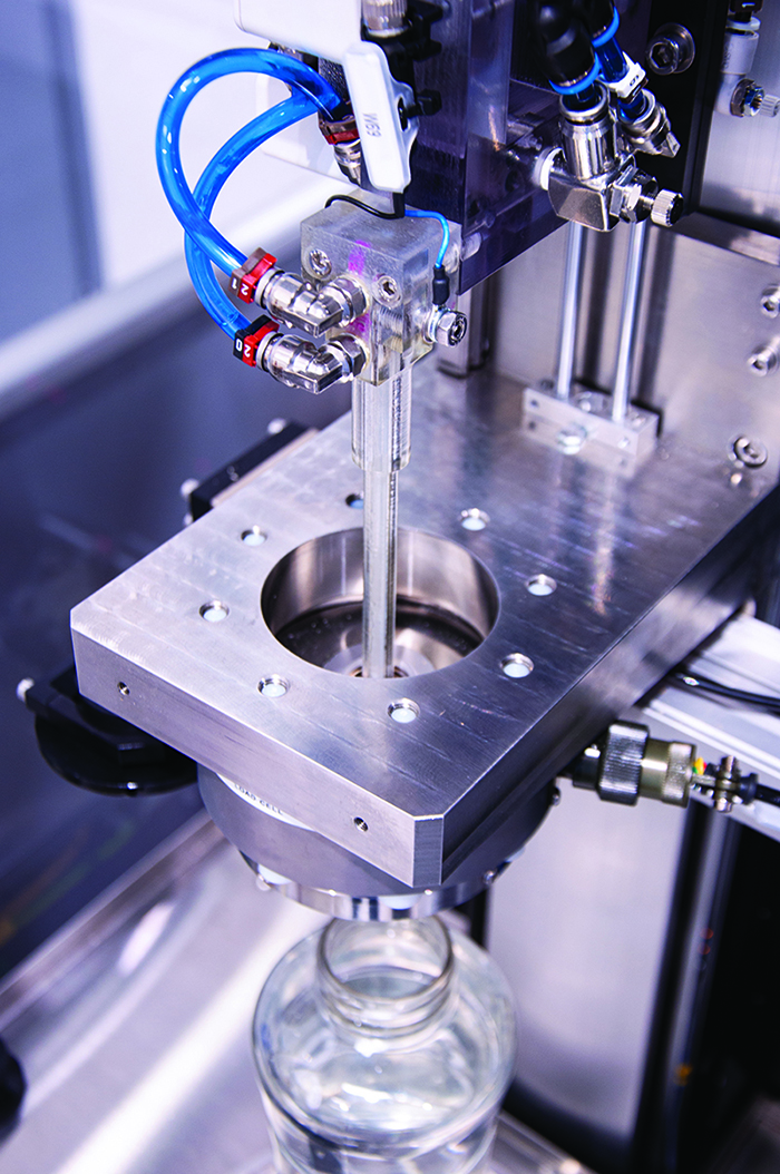
In the end, everything depends on the decision of the designers, but the fundamental principle does not change.
Control
Typical Arduino-based controller with add-on modules
FDM printer operation, including nozzle and platform temperature, filament feed rate, and stepper motors for positioning the extruder, is controlled by fairly simple electronic controllers. Most controllers are based on the Arduino platform, which has an open architecture.
The programming language used by printers is called G-code (G-Code) and consists of a list of commands executed in turn by the 3D printer systems. G-code is compiled by programs called "slicers" - standard 3D printer software that combines some of the features of graphics editors with the ability to set print options through a graphical interface. The choice of slicer depends on the printer model. RepRap printers use open source slicers such as Skeinforge, Replicator G and Repetier-Host.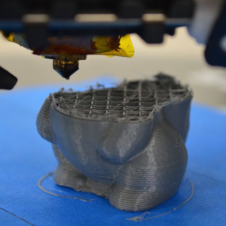 Some companies make printers that require proprietary software.
Program code for printing is generated using slicers
As an example, we can mention Cube printers from 3D Systems. There are companies that offer proprietary software but allow third-party software, as is the case with the latest generation of MakerBot 3D printers.
Slicers are not intended for 3D design per se. This task is done with CAD editors and requires some 3D design skills. Although beginners should not despair: digital models of a wide variety of designs are offered on many sites, often even for free. Finally, some companies and individuals offer 3D design services for custom printing.
Finally, 3D printers can be used in conjunction with 3D scanners to automate the process of digitizing objects. Many of these devices are designed specifically to work with 3D printers. Notable examples include the 3D Systems Sense handheld scanner and the MakerBot Digitizer handheld desktop scanner.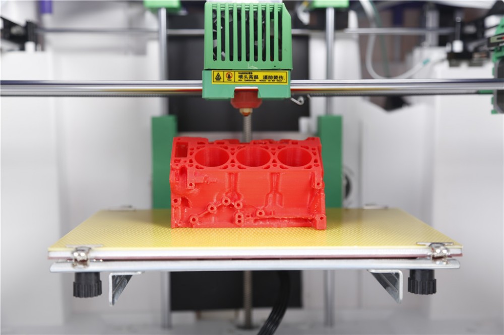
MakerBot Replicator 5th Generation FDM Printer with built-in control module on the top of the frame
The 3D printer user interface can consist of a simple USB port for connecting to a personal computer. In such cases, the device is actually controlled by the slicer.
The disadvantage of this simplification is a rather high probability of printing failure when the computer freezes or slows down.
A more advanced option includes an internal memory or memory card interface to make the process standalone.
These models are equipped with control modules that allow you to adjust many print parameters (such as print speed or extrusion temperature). The module may include a small LCD display or even a mini-tablet.
Varieties of FDM printers
Professional Stratasys Fortus 360mc FDM printer that allows printing with nylon
FDM printers are very, very diverse, ranging from the simplest homemade RepRap printers to industrial installations capable of printing large-sized objects.
Stratasys, founded by Scott Crump, the inventor of FDM technology, is a leader in the production of industrial installations.
You can build the simplest FDM printers yourself. Such devices are called RepRap, where "Rep" indicates the possibility of "replication", that is, self-reproduction.
RepRap printers can be used to print custom built plastic parts.
Controller, rails, belts, motors and other components can be easily purchased separately.
Of course, assembling such a device on your own requires serious technical and even engineering skills.
Some manufacturers make it easy by selling DIY kits, but these kits still require a good understanding of the technology.
A variant of the popular late 3rd generation Prusa RepRap printer
If you like to make things with your own hands, then RepRap printers will pleasantly please you with the price: the average cost of the popular early generation Prusa Mendel design is about $500 in a complete set.
And, despite their "homemade nature", RepRap printers are quite capable of producing models with the quality of expensive branded counterparts.
Ordinary users who do not want to delve into the intricacies of the process, but require only a convenient device for household use, can purchase a ready-made FDM printer.
Many companies are focusing on the development of the consumer market segment, offering 3D printers for sale that are ready to print “right out of the box” and do not require serious computer skills.
3D Systems Cube consumer 3D printer
The most famous example of a consumer 3D printer is the 3D Systems Cube.
While it doesn't boast a huge build area, ultra-fast print speeds, or superb build quality, it's easy to use, affordable, and safe: This printer has received the necessary certification to be used even by children.
Mankati FDM printer demonstration: http://youtu.be/51rypJIK4y0
Laser Stereolithography (SLA)
Stereolithographic 3D printers are widely used in dental prosthetics
Stereolithographic printers are the second most popular and widespread after FDM printers.
These units deliver exceptional print quality.
The resolution of some SLA printers is measured in a matter of microns - it is not surprising that these devices quickly won the love of jewelers and dentists.
The software side of laser stereolithography is almost identical to FDM printing, so we will not repeat ourselves and will only touch on the distinctive features of the technology.
Lasers and projectors
Projector illumination of a photopolymer model using Kudo3D Titan DLP printer as an example
The cost of stereolithographic printers is rapidly declining, due to growing competition due to high demand and the use of new technologies that reduce the cost of construction.
Although the technology is generically referred to as "laser" stereolithography, most recent developments use UV LED projectors for the most part.
Projectors are cheaper and more reliable than lasers, do not require the use of delicate mirrors to deflect the laser beam, and have higher performance.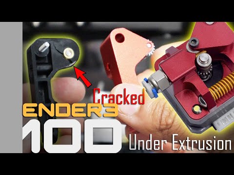 The latter is explained by the fact that the contour of the whole layer is illuminated as a whole, and not sequentially, point by point, as is the case with laser options. This variant of the technology is called projection stereolithography, "DLP-SLA" or simply "DLP". However, both options are currently common - both laser and projector versions.
Cuvette and resin
Photopolymer resin is poured into a cuvette
A photopolymer resin that looks like epoxy is used as consumables for stereolithography printers. Resins can have a variety of characteristics, but they all share one key feature for 3D printing applications: these materials harden when exposed to ultraviolet light. Hence, in fact, the name "photopolymer".
When polymerized, resins can have a wide variety of physical characteristics. Some resins are like rubber, others are hard plastics like ABS. You can choose different colors and degrees of transparency. The main disadvantage of resins and SLA printing in general is the cost of consumables, which significantly exceeds the cost of thermoplastics.
On the other hand, stereolithographic printers are mainly used by jewelers and dentists who do not need to build large parts but appreciate the savings from fast and accurate prototyping. Thus, SLA printers and consumables pay for themselves very quickly.
An example of a model printed on a laser stereolithographic 3D printer
Resin is poured into a cuvette, which can be equipped with a lowering platform. In this case, the printer uses a leveling device to flatten the thin layer of resin covering the platform just prior to irradiation. As the model is being made, the platform, together with the finished layers, is “embedded” in the resin. Upon completion of printing, the model is removed from the cuvette, treated with a special solution to remove liquid resin residues and placed in an ultraviolet oven, where the final illumination of the model is performed.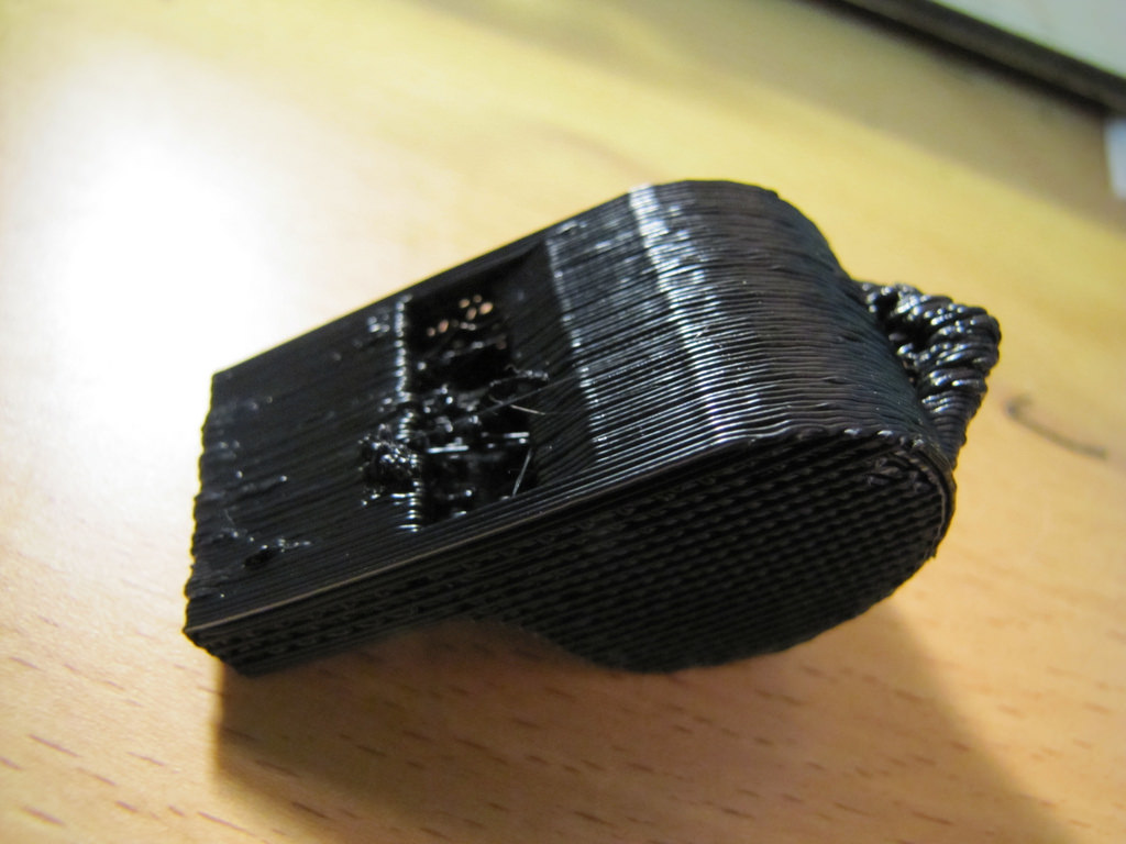
Some SLA and DLP printers work in an “inverted” way: the model is not immersed in the consumable, but “pulled” out of it, while the laser or projector is placed under the cuvette, and not above it. This approach eliminates the need to level the surface after each exposure, but requires the use of a cuvette made of a material transparent to ultraviolet light, such as quartz glass.
The accuracy of stereolithographic printers is extremely high. For comparison, the standard for vertical resolution for FDM printers is considered to be 100 microns, and some variants of SLA printers allow you to apply layers as thin as 15 microns. But this is not the limit. The problem, rather, is not so much in the accuracy of lasers, but in the speed of the process: the higher the resolution, the lower the print speed. The use of digital projectors allows you to significantly speed up the process, because each layer is illuminated entirely. As a result, some DLP printer manufacturers claim to be able to print with a vertical resolution of one micron!
Video from CES 2013 showing Formlabs Form1 stereolithography 3D printer in action: http://youtu.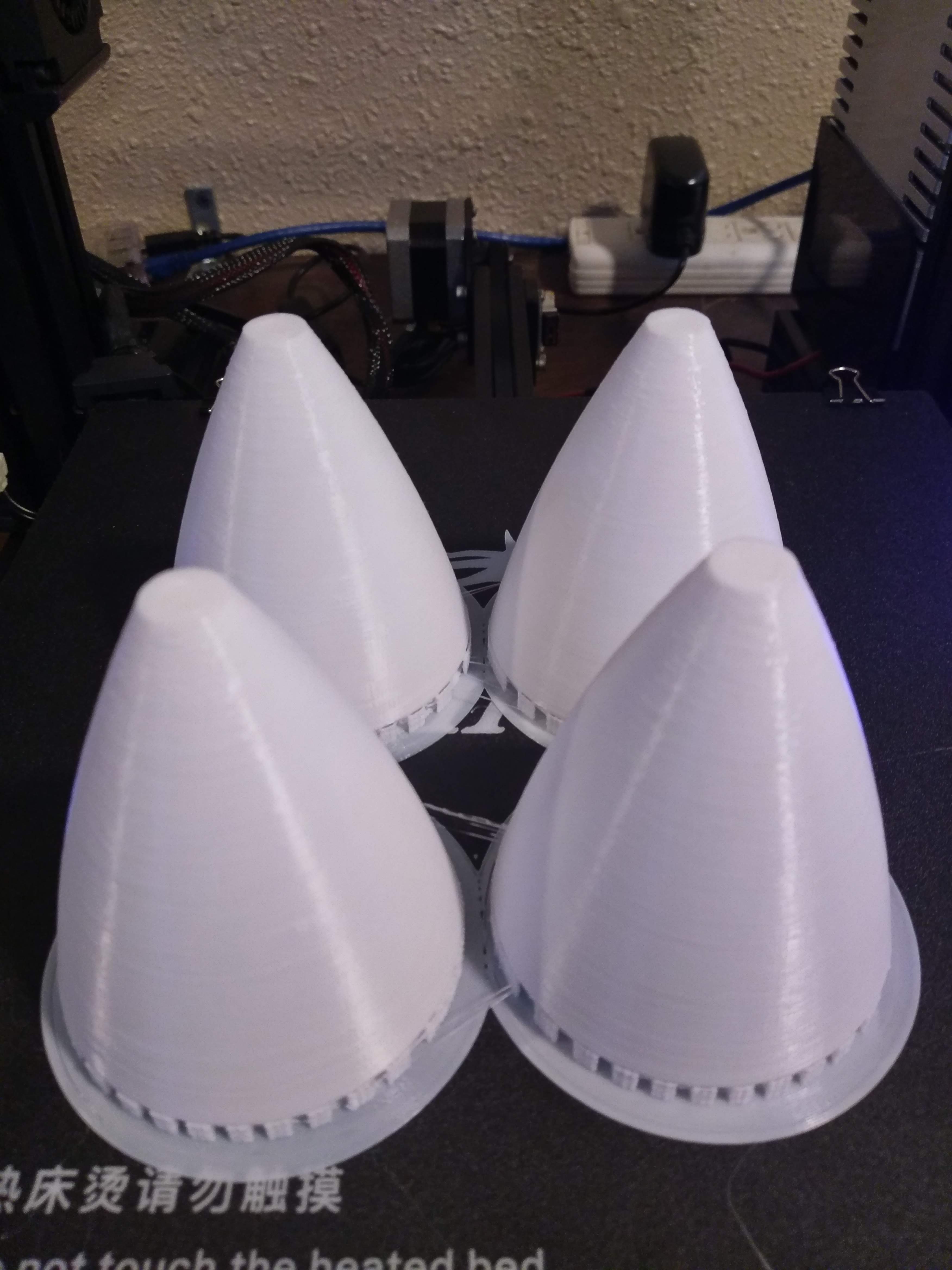 be/IjaUasw64VE
Stereolithography Printer Options
Formlabs Form1 Desktop Stereolithography Printer
As with FDM printers, SLA printers come in a wide range in terms of size, features and cost. Professional installations can cost tens if not hundreds of thousands of dollars and weigh a couple of tons, but the rapid development of desktop SLA and DLP printers is gradually reducing the cost of equipment without compromising print quality.
Models such as the Titan 1 promise to make stereolithographic 3D printing affordable for small businesses and even home use at around $1,000. Formlabs' Form 1 is available now for a factory selling price of $3,299.
The developer of the DLP printer Peachy generally intends to overcome the lower price barrier of $100.
At the same time, the cost of photopolymer resins remains quite high, although the average price has fallen from $150 to $50 per liter over the past couple of years.