3D printing text
Best Ways How to 3D Print Text on Your 3D Printer – 3D Printerly
There are many things you can print on a 3D printer, one of those being text generated 3D letters for a name, logo, or almost anything you can think of.
The process to design these things can be confusing at first, even with 3D text, so I decided to make an article to show people how to get it done.
To convert text to 3D letters ready to 3D print, you need to choose a CAD software such as Blender or SketchUp to design the 3D text. Once you’ve entered your text, you can use a rectangular frame for the text to sit on and extrude the text past the frame. Export your file as an STL after complete.
I’ll go through the process in a little more detail, as well as list the best 3D printer text generators and how to make 3D text logos using this method.
Words are great, and they look even better when they can be touched physically. The conversion does not take much time as you would require specific software for converting a 2D text into a 3D one.
This is the only part that would require time, and then you can send that 3D text file to a 3D printer for printing.
There are different ways through which you can convert your text into 3D letters and print it with a 3D printer, such as Blender, SketchUp, FreeCAD, or Fusion 360. However, to convert a plain text into a 3D one, you will require software to perform certain tasks.
Creating 3D Print Text Using Blender
Getting & Opening the Application
- Download the latest version of Blender from their official website and install the application.
After it has installed, open Blender and you should see the main interface with a cube in the middle.
Adding the Text
- Click on the cube and delete it using the ‘Del’ button on your keyboard or by pressing the ‘X’ key
- Press Shift + A to add an element and select ‘Text’ from the menu.
- It will bring up actual text for you to edit.
- Now you want to rotate the object so you can see it clearer.
- Highlight the text and press ‘R’ on your keyboard then press ‘X’ to rotate it around the X-axis.
- Then press 90, to rotate it 90° and press ‘Enter’ to accept.
- You also want to rotate it 90° around the Z axis.
- To do this, highlight the object, press ‘R’ then ‘Z’ for the Z-axis, then press 90 again on your keyboard to do the rotation and press ‘Enter’.
Time to Edit Our Text
- In order to change the letters in your text, you want to change from ‘Object Mode’ to ‘Edit Mode’. You can do this by simply pressing the ‘Tab’ button on your keyboard.
You can also change mode by clicking the ‘Object Mode’ box and selecting ‘Edit Mode’.
- Once you’re in Edit Mode, you can easily change the text as normal. Delete the placeholder text and type your desired text.
- You can also change the font by using the main command zone on Blender to your right.

- This is done by clicking on the folder icon beside the ‘Font’ then choosing one of the several fonts in the list.
- If you want your letters to be closer together and not so spaced out, you can adjust the spacing under the ‘Spacing’ section. You can adjust spacing between letters and words too.
Making Your Text 3D
- This is pretty simple to do. Within the ‘Font’ area, there is a section you can edit under ‘Geometry’ called ‘Extrude’ which, if you increase, will make your text 3D.
- You can easily adjust Extrude values using the left and right arrows, or by inputting your own values.
Secure Your Text with a Block
- Make sure you’re in Object Mode & click an empty space on the build plane to deselect all objects.
- Press ‘Shift’ + ‘C’ to make sure your cursor is centered so your objects will be in the correct place.
- Now press ‘Shift’ + ‘A’ to add an object & add a ‘Mesh Cube’.
- Scale the added cube down using the ‘Scale’ box on your left, or using the ‘Shift’ + ‘Spacebar’ + ‘S’ shortcut.
- Scale the cube to fit your writing, from front to back and side to side until it looks right. You also want to be moving the block to the right location under your text.
- Change your view by clicking the Z in the view changing section, or by clicking ‘7 on your NumPad’ so you can get a good angle and move the block nicely in the center.
- Make sure your block and text are actually well-connected and overlapping over each other.
Printing Your 3D Text
- When it comes to printing your text you want to make sure you’re printing it on its back.
- We can rotate it within Blender like we did before, so click your object, press ‘R’, ‘Y’, ‘-90’ to put the object on its back.
- Make sure both objects are selected, then click ‘File’ > ‘Export’ and export it as a .STL file. Make note of what folder you saved the file so you can easily find it to import to your slicer.
- It will be very small when you put the STL into your slicer, where you then just have to scale it up, slice it, then print your custom 3D text!
Using SketchUp to 3D Print Text
There is a free and pro version of SketchUp, and in the video below, you’ll be following the free version if you choose this option.
The great thing about the free version is you don’t need to download any software. It’s all done straight from the SketchUp Browser App.
Adding text is very simple.
After clicking the ‘3D text’ option, the following box will pop-up where you can enter your custom text.
Below is a cool example of something you can create from following the video tutorial.
You can choose to just create the simplified text with the supporting block underneath like in Blender. With the video below, you can easily figure out how to navigate and adjust shapes and text to create your desired design.
3D Printed Text Using FreeCAD
The video below does a pretty good job showing how to create your 3D print text on FreeCAD, as well as creating an embossed text.
It’s pretty easy to follow, and once you get the hang of it, you can 3D print plenty of your custom text ideas, signs, and tags.
The picture below is after creating the text and extruding it by 2mm.
Now let’s get a nice rectangular frame on that text to support it and extrude that by 2mm also.
Then we extrude the text even further to get it sticking out of the frame, 1mm works out pretty well.
Select the files simultaneously then export them using ‘File’ > ‘Export’ and save them as a .stl file. You can then simply import that into your slicing software to get ready to 3D print your text!
3D Print Text Generator Using Fusion 360
Fusion 360 is a pretty advanced design software which can definitely create some great 3D text. If you need to design something a little more complex, it’s a great software to use, although, it works really well for creating 3D text.
The video below takes you through the process.
3D Print Text Troubleshooting
Some people run into issues such as gaps in the lettering of their 3D text which can be caused by either your slicer not correctly processing the model, or by under extrusion in your 3D printer.
If your problem is caused by your slicer, it’s hard to tell, but you can try changing your slicer to see if the model prints differently. Many people have seen massive differences in print quality just by using a different slicer, so I’d give this a try.
If the problem is under extrusion, I’d slow down the printing speed and also calibrate your e-steps to make sure you are extruding as much material as your 3D printer says you are.
Another thing you can do is set your infill to 100% to properly fill in the gaps in your model, as well as increase the overall wall thickness of your print.
When it comes to creating embossed text or recessed letters, you can do this within your CAD software, usually by a dragging function, or by inputting the distance you want your text to move.
It is done different with separate software, so try to figure out where you can input these values to move your 3D text.
If you are having trouble reading your 3D text, a great font you can use for 3D printing text actually happens to be Comic Sans since the spacing in the font is done very well and the letters are bold enough to make it easier to read, perfect for smaller text.
Arial is another font that works well for 3D text, as well as Montserrat, Verdana Bold, Déjà vu Sans, Helvetica Bold, and other heavy weight Sans-Serif or Slab-Serif fonts.
Step-by-step guide with images! – 3D Solved
3D printing allows us to create all kinds of cool stuff. Amongst them is the ability to create 3D letters for a name or logo. In this article, I will demonstrate how to design and 3D print your desired text using 3D modeling software.
I’ll give you the recommended slicer settings and even a walkthrough on how to 3D print both computer typed and your handwritten texts. The process is quite simple and won’t take you too much time to get it done.
Table Of Contents
- 3D modeling software for printing text
- How to create the text
- Slicer settings for 3D printing text
- Model Orientation
- Layer Height
- Infill, Wall Thickness, and Top Layers
- Bonus: Convert handwritten text to 3D print
- Conclusion
3D modeling software for printing text
In order to 3D print your desired text you will need to use a 3D modeling app.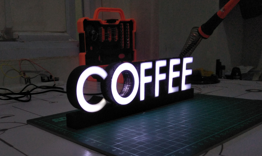 Most of them can be used for this purpose so the choice is yours. The ones that come to mind for this task are Tinkercad, Fusion360, and SketchUp. Tinkercad is going to be my choice as it can be used for free, is easy to learn, and can be used without the need to download and install the program (it is browser-based).
How to create the text
To get started with the project you will need a Tinkercad account. Head over to their website and follow the instructions to create an account. Once you got your account, you will be asked to do a tutorial to learn the basic concepts of Tinkercad, I suggest you do it as it doesn’t take much time.
When you are finished with the tutorial, it is time to start the design! In this case, I will show you how to create step by step a simple nameplate. Click the “Create new design” button on the upper left section of the homepage.
- 1. Create a Base
Select a “box” from the “basic shapes” on the right side and drag it onto the workplane.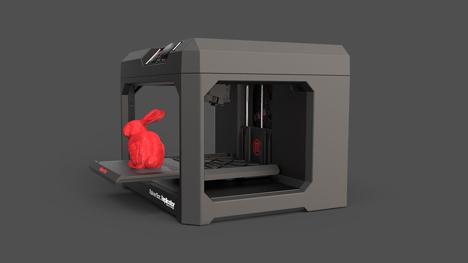 Resize the box into a thin rectangle as big as you want the nameplate to be. You can specify the exact measures you want it to have by clicking the white and black squares that show up when you click the shape. Tinkercad displays the measurements as millimeters.
- 2. Create and Position The Text
Go to “Text and numbers” on the right side, select “Text” and drag it onto the workplane. Expand the “Text” options and write the desired name. Then adjust the “text” height so it is a little higher than the base and drag it into the base. If you need to resize the “text” to fit the base you can shift+click one of the “Text” squares to change its size altogether. When you are happy with the looks, select both shapes (base and text) by shift+click and click on “Group”.
- 3. Export The File Ready to 3D Print
Now that our design is finished click on the “Export” button on the upper right side. Select “.STL” and the file will be downloaded to your PC ready to be sliced and 3D printed.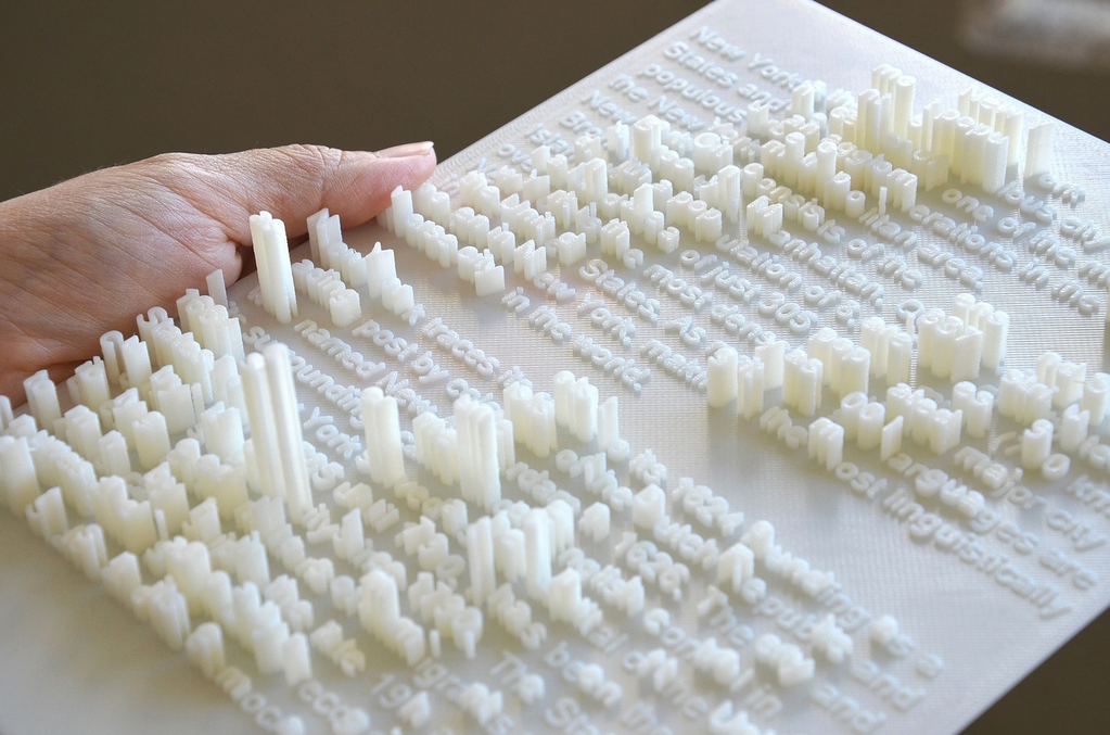
- 4. Extra Option to be Able to Screw The Nameplate
If you would like to screw to nameplate to a surface, you can add holes on the sides. To do this select the “Cylinder” from the basic shapes and drag it onto the workplane. Adjust the Cylinder’s height to match the base’s height. Now duplicate the Cylinder and put them on the sides of the nameplate.
Select the “Hole Cylinder” from the “Basic shapes” and drag it onto the workplane, this shape will create the hole for the screws. Resize the “Hole Cylinder” while holding Shift to a convenient size for the screws you will use later and duplicate the “Hole Cylinder”. Finally, drag the “Hole Cylinders” to the middle of the “Cylinder”, select all shapes, and hit the group button.
Final Look, ready for 3D printing.Slicer settings for 3D printing text
Model Orientation
Make sure your model is positioned in a way that will allow you to print it without the need for supports.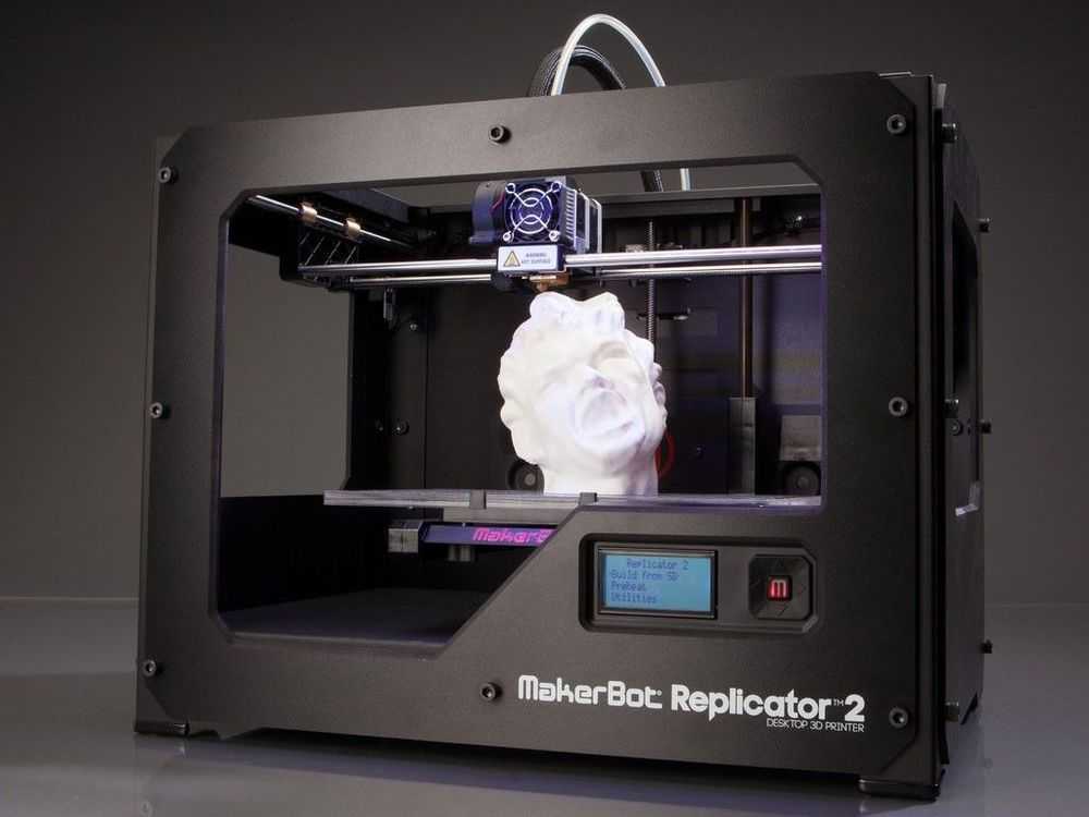 That usually means with its back against the print bed. In the case where you can’t avoid the need for supports try to have them away from the letters.
Layer Height
The layer height you can use depends on your nozzle’s diameter. Check this article to see the range you can use for your nozzle’s diameter. Having said that, as we don’t have any details in the Z-axis, we can use a high layer height to save some printing time. It would be a good idea to have the layer height be a multiple of the model’s height.
Infill, Wall Thickness, and Top Layers
We want the letters to be as solid of a structure as possible so they don’t break. To achieve that use a high wall thickness, ideally a multiple of the nozzle’s diameter (1.2mm for a 0.4mm nozzle). That way there will be little to no infill in the letters. For the top layers use a multiple of the layer height (1.2mm top layer thickness for 0.3mm layer height). Having a few solid top layers will give a better look to the model.
As you can see, it is rather easy to create your own plaque. Additionally, if you want to achieve a smoother surface both on the letters and on the plaque, you could try enabling ironing.
Bonus: Convert handwritten text to 3D print
You can 3D print your very own handwritten texts and it is very easy to do. Follow these simple steps:
- 1. Draw your Text
Draw your text preferably using a thick black marker so there is a good contrast with the sheet of paper. This way we can ensure there will be no problems when we convert the image to an SVG file.
- 2. Scan your Text
Use a scanner (there are many mobile apps that can scan an image) to scan your written text as a PNG file. I personally chose to use CamScanner (Android |Iphone). Then convert the PNG file into an SVG file so it can be imported to Tinkercad. I used this free online converter for my text.
- 3. Import the File to Tinkercad
Import the SVG file to Tinkercad by clicking on the “Import” button on the upper right side. Once you selected your file to be imported, scale it down to 5% as these files are quite large, and click “Import”. If you wish to resize the image after it is imported, use Shift+click and adjust the size.
- 4. Export File
Now we are ready to export the file to the slicer. Click “Export” on the upper right side and select STL.
My 3D printed text resultsConclusion
As we saw, we can easily create custom-written signs. Although the steps are different for handwritten and computer typed texts, both options turn out to be a good starter project to get used to modeling apps and turning ideas into real-world objects.
We created a recommended products section that will allow you to remove the guesswork and reduce the time spent researching what printer, filament, or upgrades to get, since we know that this can be a very daunting task and which generally leads to a lot of confusion.
We have selected just a handful of 3D printers that we consider to be good for beginners as well as intermediates, and even experts, making the decision easier, and the filaments, as well as the upgrades listed, were all tested by us and carefully selected, so you know that whichever one you choose will work as intended.
An easy way to 3D print a logo, image, text using only a Cura slicer / 3D printers, machines and accessories / iXBT Live
Recently, a guide was published here on how to print text, a logo, and I think this is not the easiest option. I show how to get a model for printing faster, without using additional programs, but this method has disadvantages.
We need a Cura slicer, along with 3D models and gcode, it can open *.bpm, *.png *.jpg *.jpeg images and convert them into a 3D model using the extrusion method (analogue of the boss tool in a 3D compass, solidworks, etc. .d.).
We open the image we like through Cura and we are greeted by the image conversion dialog:
Height is the future height of the logo / text, the base is the background, you can set it to 0, or you can make some “base” if there are small elements and they do not need to be separated , then I advise you to immediately do it with a base of at least 0. 3 mm, then the trifle will not fly away during the printing process. If the elements need to be separated, then in the print settings it is better to select printing on the Raft substrate, it will then be easier to separate small elements from it and they will not fly off during the printing process.
Width and depth are X, Y dimensions, it is better not to touch. But smoothing is an interesting slider, in fact, it sets the conversion factor, and the higher it is, the closer the light areas will be to the dark ones, and the smaller the difference between them will be. For example, I'm using the ixbt.com logo
Top with minimal anti-aliasing, middle with standard (about 2-5%), and bottom with maximum. In this case, the specified height - 5 mm is not achieved, in the upper version it is 3.9 mm, and in the lower 2.7 mm.There are two extrusion patterns "dark above" and "light above".
The top one is “dark above”, the bottom one is “light above”. If we get closer, the minus of this method pops up, as a rule, not one color is used to create a beautiful picture, but a gradient, so the darkest areas rise to a given height, and those that are lighter linearly are lower, resulting in "corner extrusion" and uneven edges on the model.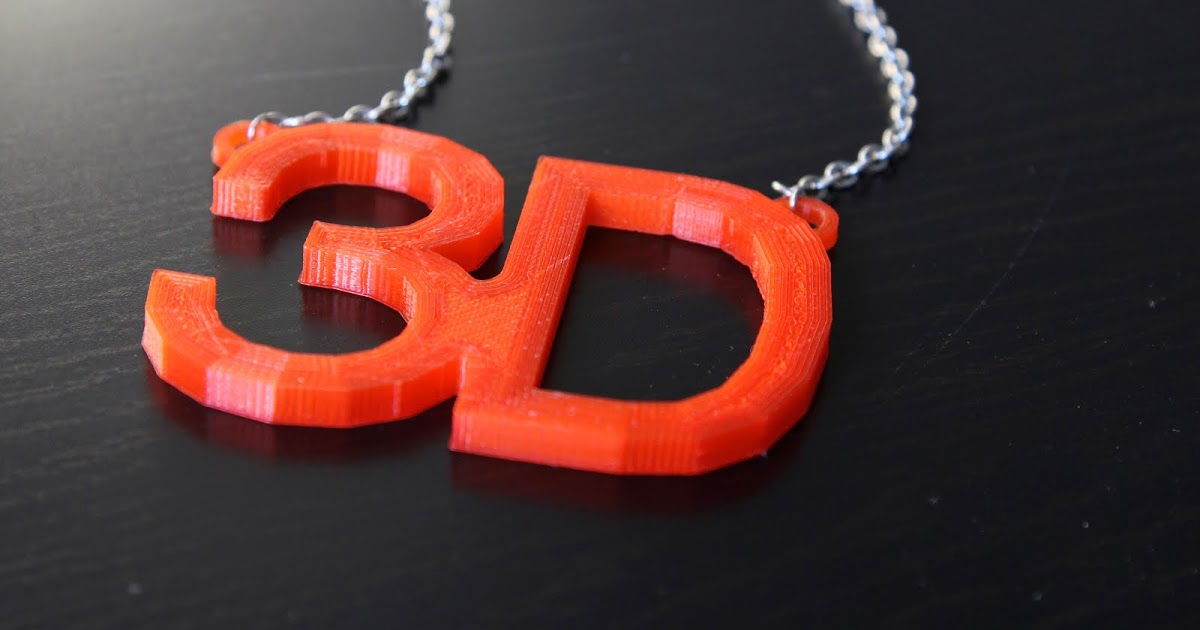
But after slicing, small irregularities will practically not be visible.
In paint, I added a contour, and when exporting the model, I made the base 1 mm thick
After printing, it remains to remove unnecessary elements and you will get a finished keychain. It was also possible to make the “Light above” option, and then fill the contour in the shape of the logo with melted plastic of a different color.Print settings: 0.6 nozzle, layer height 0.2, 150mm/s, ABS plastic. I print on an open printer, so I also added Raft. You can see over-extrusion on the upper layers and floating corners, this is more likely to be related to the printer settings.
In this way, for example, you can make cookie cutters, print key rings, make templates (patterns), etc. without using 3D modeling. And in order for the borders to be rigid, it is better to use one color, preferably black, to create an outline.
News
Publications
Warning: this is really what reflected in the title - first glance. To whom life is not sweet without detailed and detailed test reports with a large number of dry figures, I recommend...
Due to the lack of a legal framework and increased risks of fraud, banks often avoid working with cryptocurrencies and are not ready to offer them to their clients. However, the most advanced of...
Looking for a lightweight modern laptop for work or study? Today we are talking about an ultrabook with modern hardware at an affordable price. Disassembly, autonomy tests and general impressions of use in ...
Remember the ad from the 90s? A woman's voice sang: Orion Chokopay. Orion is the manufacturer, Chocopai is the product. Nothing unusual. However, the company is in a long-term lawsuit...
I recently came across a video by American blogger Marquis Brownlee, in which he showed the operation of Oculus Quest Pro glasses connected to a MacBook. What do you think he showed? The glasses displayed...
Trabzon is a typical Turkish city with many restaurants and cafes for every taste and budget.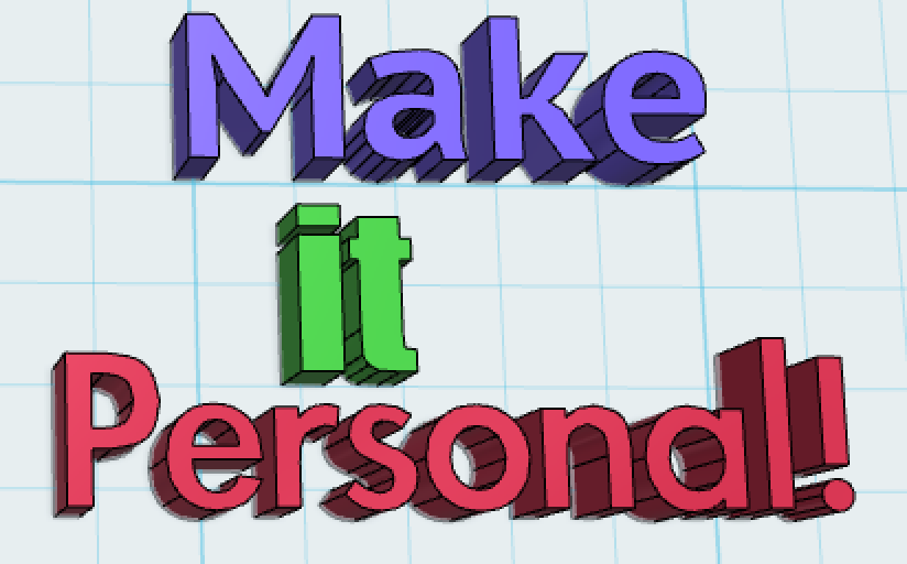 Due to the fact that the city is located on the Black Sea coast, in restaurants you are always...
Any text on a 3D printer in a couple of minutes
My wife's birthday was coming up. And what's the best gift? That's right, handmade. and I decided to print the text on a 3D printer, something like a topping on a cake. I climbed Singivers and 3Dtoday, but did not find anything interesting. It would seem a simple task, but it is almost impossible to do anything artistic in SolidWorks. I came across an article that described how to solve the problem using CorelDraw and SolidWorks. Using this article, I about ... lost a lot of time, but nothing good came of it. Solid stubbornly did not want to make a boss, complaining about all sorts of problems. There was little time left, spitting on everything, I decided to go my own way. For those who are interested, welcome under cat.
And so, to solve the task, we need CorelDraw and registration on the site https://www.tinkercad. com/ Well, in addition, fantasy. So, let's begin.
Start CorelDraw and create a new document. Corel will ask you to select the dimensions of the document. As dimensions I use the size of the printable area. But this is optional.
Now select the text tool and type the desired text.
Now the magic begins. Select the Block with written text and select the menu item “Object” - “Disconnect curly text, symbols ...” Or use the keyboard shortcut Ctrl + K
Attention. The first time the command is used on a block of text, the text is divided into words. Thus, in order to divide the text into letters, it is necessary to go through all the letters, and if they are selected by several characters, it is necessary to repeat the operation on an undivided block of text and do so until the entire text is divided into individual letters.
Now, after all the text has been divided into individual letters, artistically lay out the letters the way you want them to be printed by a 3D printer. For example like this:
All. The layout of what we will turn into a three-dimensional figure is ready. And now the most important thing begins. We need to export the resulting image to SVG format. To do this, in CorelDraw we do the following: “File” - “Save As”
in the window that opens, give a name to our file and select the file type “SVG”
Now click the “Save” button And the following window opens:
Now we check that the document settings match those that we entered when creating it. So that the units of measurement are in millimeters and Be sure to export the text as curves. Those. We do as shown in the figure. do not touch other parameters. We press OK.
All file saved. Now go to the site https://www.tinkercad.com/. If you are not registered there, register, log in and create a new project.
And now the magic.
in the right corner press the IMPORT button
An import window will open in which you must drag or select your SVG file.
After selecting a file, tinkerkad will start swearing that the workspace size is too large:
There's nothing to worry about. It just seemed to him that the model was larger than it actually was. In the "dimensions" field, we bite off a couple of zeros so that they match the dimensions of your printer's table. For example, I have a table 200x200 mm. So I do this:
and click the "Import" button. All. Our text is not only imported, but also became voluminous.
Now we have a three-dimensional model, which we can adjust in size and thickness, export to an STL file (for this we use the “EXPORT” button). Well, then you know what to do.
Here are some examples of my quick work:
Sorry for the quality of the photo. Made them on the phone. Their goal was to show how it can turn out. I hope the article was useful to you. If the article turned out to be useful for you, share the link to it with your friends on social networks, websites and forums on 3D printing.