3D printing stepper motor
3D Printer Stepper Motors & Stepper Drivers
Sort byRelevanceBestsellersCustomer ReviewsPrice, Low to HighPrice, High to LowNew arrivalsHighest Discount
-
BIGTREETECH Stepper Motor Driver 9 Model types- High-quality
- Different versions available
- Upgrade option
-
BondTech NEMA17 Pancake Stepper 25mm- Removable cable
- High torque
- Original Bond Tech
-
BondTech Heatsink- Better heat dissipation
- Self-adhesive backing
-
Anycubic Stepper Motor 5 Model types- Original spare part
- By Anycubic
-
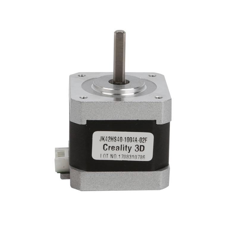
Creality Stepper Motor 8 Model types- Original spare part
- From Creality 3D
-
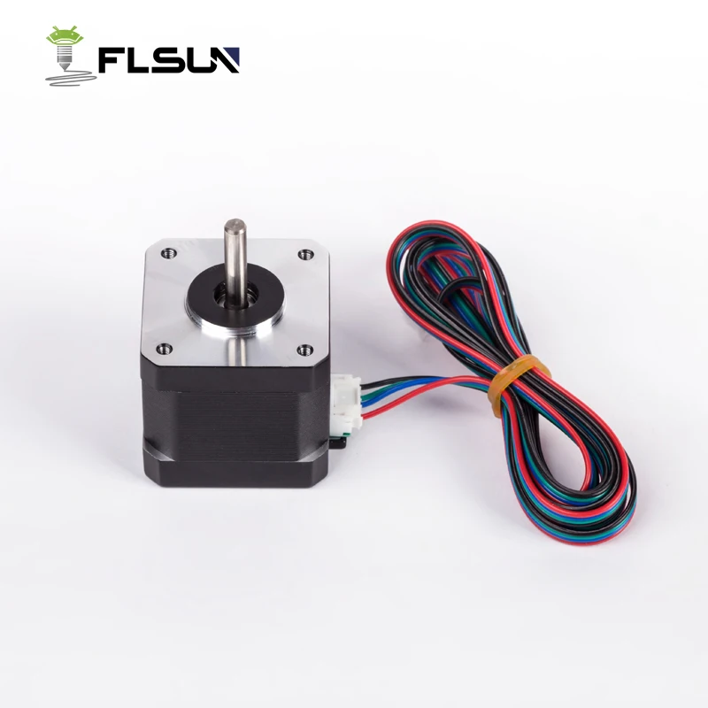
FLSUN Stepper Motor 3 Model types- Original spare part
-
BondTech NEMA17 Pancake Stepper 22mm- Fixed cable
- High torque
- Original Bond Tech
-
BIGTREETECH EZ Stepper Driver 2 Model types- 2-in-1 driver and heatsink
- Quiet movements
- Very durable
-
BondTech NEMA17 Geared Stepper- Planetary gear
- High torque
- Original Bond Tech
-
E3D Hemera XS Motor- Original spare part
- For E3D Hemera XS
- Including drive gear
-
BIQU Stepper Driver- Original spare part
-
BIGTREETECH EZ Driver Connector- Adapter for increased compatibility
-
E3D Hemera Motor- Original spare part
- For E3D Hemera
- Including drive gear
-
Zortrax Extruder Motor Set- Original spare parts
-
Artillery Stepper Driver- Original spare part
- From Artillery
-
Artillery Stepper Motor- Original spare part
- From Artillery
All prices incl. VAT.
What is the Best Stepper Motor/Driver for Your 3D Printer? – 3D Printerly
If you’ve wondering just which stepper motor/driver is best for your 3D printer, you’re in the right place. It’s a quite overlooked part of a 3D printer and it deserves a bit more of an informed decision rather than just sticking with what your printer came with.
Many people have reported prints improving after installing a better stepper motor on their 3D printer so which one is best for your 3D printer?
For such an essential part of a 3D printer, I’ve wondered which stepper motor is the best so I created this post to find that out so read along for the answers.
For the people that came for a quick answer, the best stepper motor for your 3D printer is going to be the StepperOnline NEMA 17 Motor. It’s highly rated on Amazon and is the #1 listing for Electric Motor Mounts. Low noise, long lifetime, high performance and no loose steps!
Many have described it as a plug-and-play motor but it does require a bit of know-how, but shouldn’t take too long at all to install.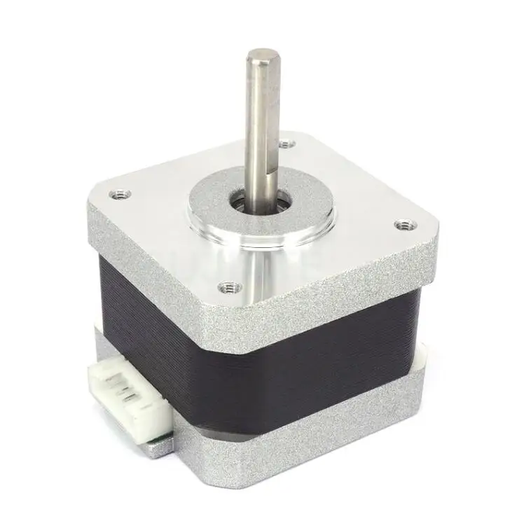 Once you install this stepper motor, any slip problems you’ve had previously should be dealt with easily.
If you are looking for the best stepper motor driver, I’d go for the BIGTREETECH TMC2209 V1.2 Stepper Motor Driver from Amazon. It significantly reduces noise in 3D printers and produces much smoother movements overall.
Now let’s get into what makes a stepper motor so important.
What are the Key Functions of a Stepper Motor?
Under the hood of every 3D printer out there, you’ll find a stepper motor.
The proper definition of a stepper motor is a brushless DC electric motor that divides a full rotation into an equal number of steps. The position of the motor can be ordered to move and hold at certain steps and used at your desired torque and speed.
In simpler terms, stepper motor is what the motherboard uses to communicate to the motors of your 3D printer to make it move around the various axes. It gives the precision, speed and positioning of how things move so it’s a very vital component of a printer.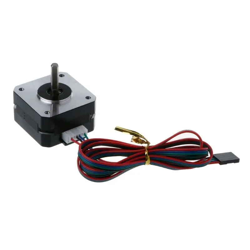
The reason stepper motors are used in 3D printers is because of their wide range of benefits such as low cost, high torque, simplicity, low maintenance while being highly reliable, and works in just about any environment.
Also on the technical side of things, they are very reliable because there are no contact brushes in the motor, meaning the life of the motor depends solely on the longevity of the bearing.
Stepper motors are also used in medical instruments, engraving machines, textile equipment, packaging machines, CNC machines, robotics and much more.
What Makes a Stepper Motor Better Than Others?
Now it’s important to know that there are many different sizes, styles and characteristics that a stepper motor can give you.
The factors that are important to us are the ones that work best for a 3D printer specifically. Since we need to consider how much work the motor is going to be doing, we take a few things into account.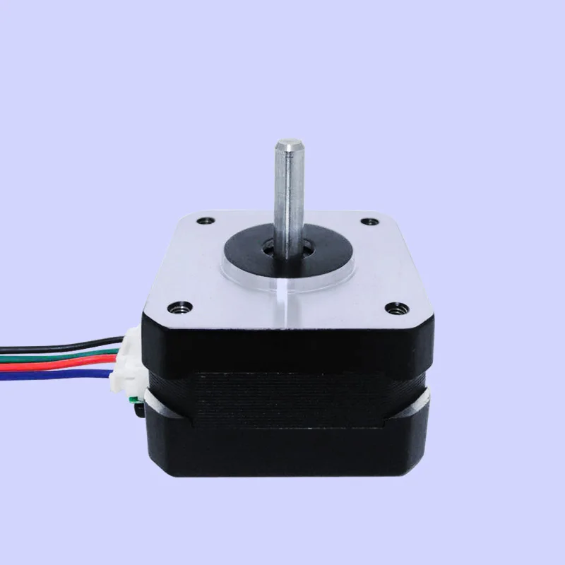
The main factors that make a stepper motor better than another are:
- Torque rating
- Size of motor
- Step count
Torque Rating
Most stepper motors have a torque rating which roughly translates to how powerful the motor is. Usually, the bigger the size of the motor, the more torque rating you’ll have because they have a better ability to deliver power.
You do have smaller 3D printers such as the Prusa Mini which would require less torque than lets say, an Anycubic Predator Delta Kossel so do keep the size of your printer in mind.
Size of Motor
You have a wide range of sizes for stepper motors, but many can definitely be too strong for a simple 3D printer, which doesn’t require too much performance.
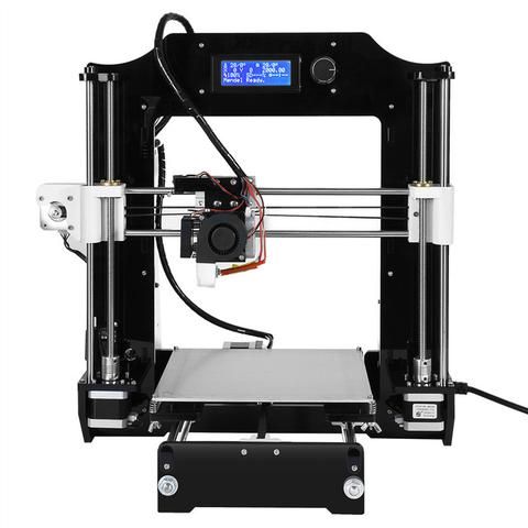
For 3D printers, we generally go for the NEMA 17 (face plate dimensions 1.7 by 1.7 inches) because they are large enough to get the job done.
You would usually use larger NEMA motors in products that require industrial applications or CNC machines.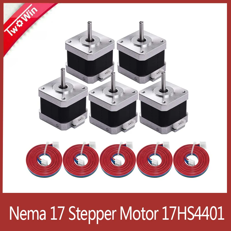 Do keep in mind that NEMA simply describes the size of the motor and not it’s other characteristics. Also, two NEMA 17 motors could be very different and are not necessarily interchangeable.
Step Count
The step count is what gives us the precision that we need in terms of movement or positioning resolution.
We call it the number of steps per revolution and it can range anywhere from 4 to 400 steps with the common steps counts being 24, 48 and 200. 200 steps per revolution translates to 1.8 degrees per step
For you to get a high resolution, you will have to sacrifice speed and torque. Basically, a high step count motor will have lower RPMs than another motor of a lower step count of comparable size.
If you need higher step rates to turn the motors efficiently, it will require more power so the torque comes in lower and vice versa. So if you want great precision of movement, you will need high step counts therefore reducing the amount of torque you have.
Best Stepper Motors You Can Buy Now
NEMA-17 Stepper Motor
StepperOnline NEMA 17 Motor as recommended at the start of this post is a great choice for a stepper motor.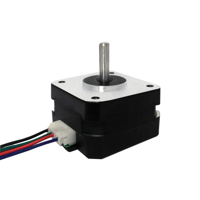 Thousands of happy customers have used this stepper motor with great success with its high quality and flexible customization.
It comes neatly packaged and is a bipolar, 2A motor with a 4-lead and 1M cable/connector. The only downside here are the cables are non-detachable. Do note that the colors of the cables don’t necessarily mean they are a pair.
The way to determine wire pairs is to spin the shaft, then touch two wires together and spin it again. If the shaft was more difficult to spin, those two wires are a pair. Then the other two wires are a pair.
Once you do install this stepper motor, your performance should be second to none and smooth for years to come.
Usongshine NEMA 17 Motor is another choice that is well-liked between 3D printer users and is slightly smaller than the above choice. This high torque stepper motor is made of high quality steel and has great performance.
A few advantages of this stepper motor is its effective thermal conductivity and quality control for each stepper motor that’s sold.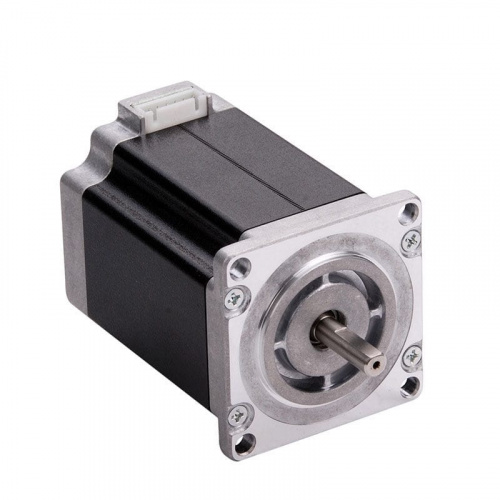 You get your stepper motor (38mm), 4pin cable and connector a strong/quiet device to assist you in your 3D printing journey.
The wiring is better set out, with the black and red wires being A+ & B+ then the green and blue wires being A- & B-.
Customer service is also at the forefront of their product so you have good peace of mind after your purchase.
Even at print speeds of 120mm/s+ this stepper driver will deliver amazing performance every time.
Best Stepper Motor Driver for 3D Printers (Upgrades)
Kingprint TMC2208 V3.0
There are many stepper motor drivers out there you can get for your 3D printer, but you’ll want to get one that works well for your particular machine.
The Kingprint TMC2208 V3.0 Stepper Damper with Heat Sink Driver (4 Pack) from Amazon is a great choice that many users have loved using. One user said he went from using standard drivers to these, and the difference in noise and control was astounding.
Previously, he had a very noisy 3D printer that also had jitters throughout the printing process, but now, the printing is silent and really smooth.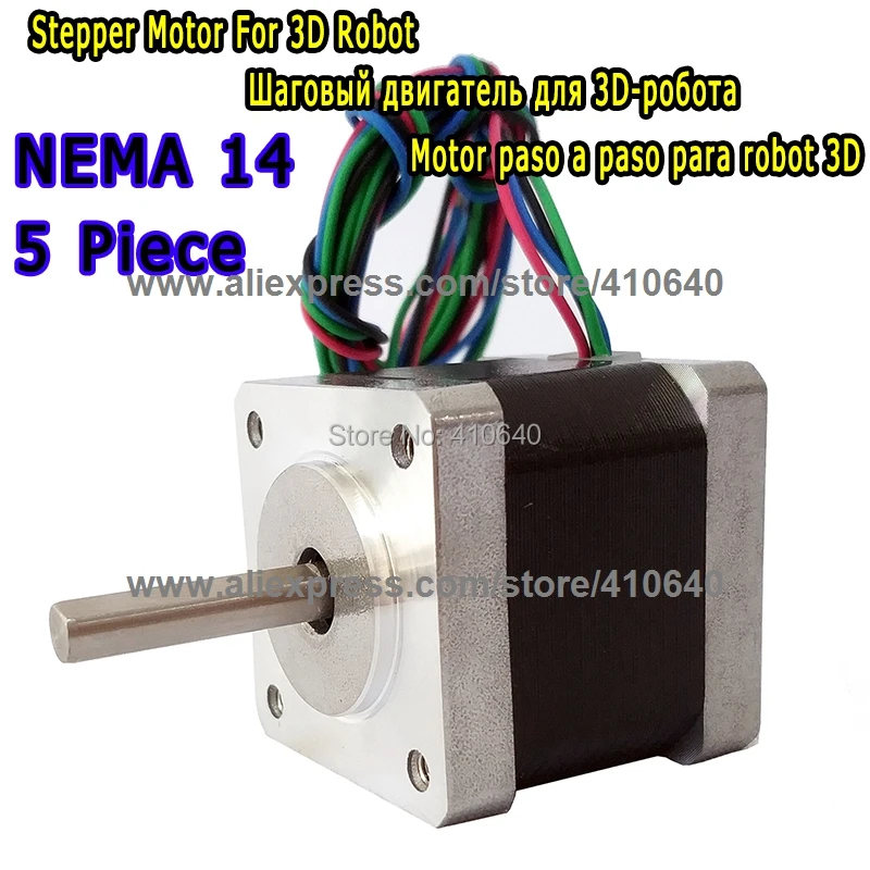 They have a good large exposed heatsink area, so the installation is made a little easier.
The difference between these and classic 4988 steppers are huge. Another nice feature that has been added to this is the pin headers for UART access, so you don’t have to solder them on yourself.
One user mentioned how she didn’t realize 3D printing could be so silent, making a really dramatic difference in noise. If your 3D printer vibrates a lot, even to the point where your table vibrates like another user, you’ll want to get these installed as soon as possible.
After installing this, the loudest thing on people’s 3D printers are the fans.
BIGTREETECH TMC2209 V1.2 Stepper Motor Driver
BIGTREETECH is a very well-known 3D printer accessories company that produces really reliable and useful parts. If you are looking for some of the best stepper motor drivers, you’ll want to look into getting yourself the BIGTREETECH TMC2209 V1.2 Stepper Motor Driver from Amazon.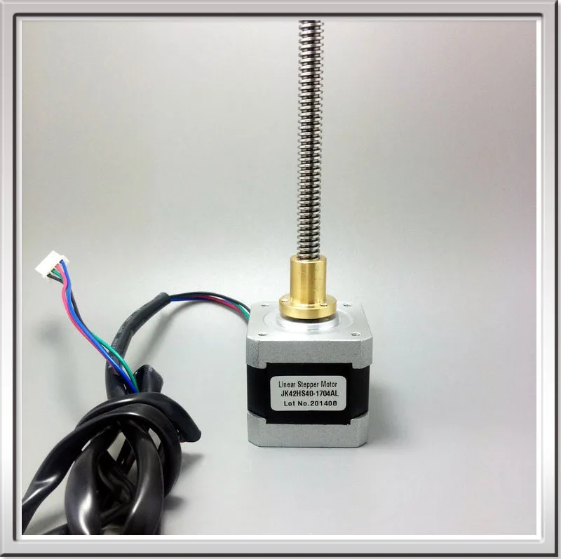
They have a 2.8A peak driver, made for SKR V1.4 Turbo, SKR V1.4, SKR Pro V1.2, SKR V1.3 Motherboard, and comes with 2 pieces.
- The motor makes it very hard to lose steps; ultra-quiet mode
- Has a large thermal pad area to reduce the temperature of the work
- Prevents motor shake
- Supports stall detection
- Supports STEP / DIR and UART mode
The TMC2209 is an upgrade over the TMC2208 in that it has an increased current of 0.6A-0.8A, but also increases the function of stall detection. It has some cool technology within the part such as SpreadCycle4 TM, StealthChop2TM, MicroPlyer TM, StallGuard3TM & CoolStep.
These do things such as give more control, reduce noise, and provide a smoother operation.
One user said they paired these stepper motor drivers with the SKR 1.4 Turbo, along with a new screen and now their 3D printer is smooth and silent. You won’t regret making this great upgrade if you are facing issues of noise and large vibrations.
stepper motor choice, which is better
With the advent of 3D printers, people's lives have become much easier. Devices are successfully used in many areas - dentistry, industry, jewelry and medicine. Now a 3D printer is not a luxury item, but a design that is quite affordable. But still there are those who decide to independently manufacture printing presses. Next, let's talk about how to choose a stepper motor for a future 3D printer and what features should be taken into account.
Motor on a 3D printer
In the design of a 3D printer, the main function for the movement of the extruder along the axes is performed by stepper motors. They have low weight and high torque.
A stepper motor is a motor without a commutator, whose rotation is not smooth, but discrete (in steps). By setting the speed and duration of the pulses, you can make the device rotate in a certain direction. In this case, it is possible to adjust the direction of rotation and the number of revolutions of the rotor.
If we talk about the design of such devices, then there are three main types:
- Motors with variable magnetic resistance - have several poles on the stator and a rotor made of soft material, and 3 windings independent of each other. This type is practically not used.
- Permanent Reluctance Motors - Includes stator and magnetized rotor. Such motors have 24 to 48 steps per revolution.
- Devices combining variable and constant magnetic resistance (hybrids) - combination of the best properties of an alternating and constant rotating motor. The number of steps is from 100 to 400.
The hybrid engine is the most common design, which, in turn, is divided into unipolar and bipolar types.
Which stepper motors to choose for a 3D printer: the best options
When buying a rotator for a 3D printer, you should pay attention to the following parameters:
- rotating structure size;
- holding torque - from 2.
 5-4 kg/cm;
 - rated current - optimal version for 1.7 A;
- Shaft - Diameter must match the design of the printer.
The most common motors that are installed on the design of the printing device are bipolar with four leads. Such structures in the event of a breakdown are easy to find and replace.
NEMA marked rotary motors are installed in 3D printers.
NEMA is a National Electrical Manufacturers Association that standardizes rotating devices in terms of flange size and fit. This standard allows different manufacturers to produce engines according to certain parameters, depending on the marking.
Most popular models in the NEMA series:
- NEMA 17 with 42*42mm flange;
- NEMA 23 with 57*57mm flange;
- NEMA 34 size 86*86mm.
Stepper motor drivers for 3D printer
To control motors in 3D devices, drivers installed in the board slot were developed.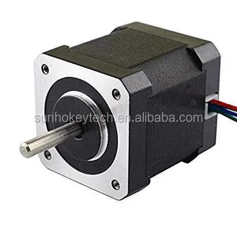
There are several types of drivers:
- Constant voltage - such drivers are inefficient and are used in a product with low speeds.
- Two-Level - These controllers support stepping and half stepping. They reduce engine heat and are efficient in operation.
- PWM drivers are the most popular on the market. They are highly intelligent and have many additional features.
Also, when choosing a driver, you should pay attention to the following parameters:
- current strength;
- supply voltage;
- availability of optoisolated inputs;
- availability of resonance suppression mechanisms;
- availability of protocols necessary for engine operation;
- surge protection;
- micro stepping;
- driver quality.
It is quite possible to assemble a high-quality 3D printer if you follow the recommendations and carefully study the design devices. It is quite possible that such a printing press will cost its owner less. But for beginners, we recommend ordering ready-made 3D devices in specialized stores. So you can learn the basics of 3D printing and get acquainted with the printer device. Good luck!
- May 17, 2021
- 4343
Get expert advice
3D printing for the newest. From A to Z. Steppers, drivers and some magnetic field.
In continuation of the previous post for novice users of 3D printers.
This time I will talk about control boards, common drivers for stepper motors and a little theory about their work. Unfortunately, the post has a limit - 65535 characters, and I no longer fit into them to describe the common control boards in more detail, so they will be in the next post, just like the analysis of firmware, positive aspects and disadvantages.
Existing 3D printers have grown out of large machines, from which they borrowed kinematics and a control method, which consists in sequentially transmitting coordinates to move the hot end.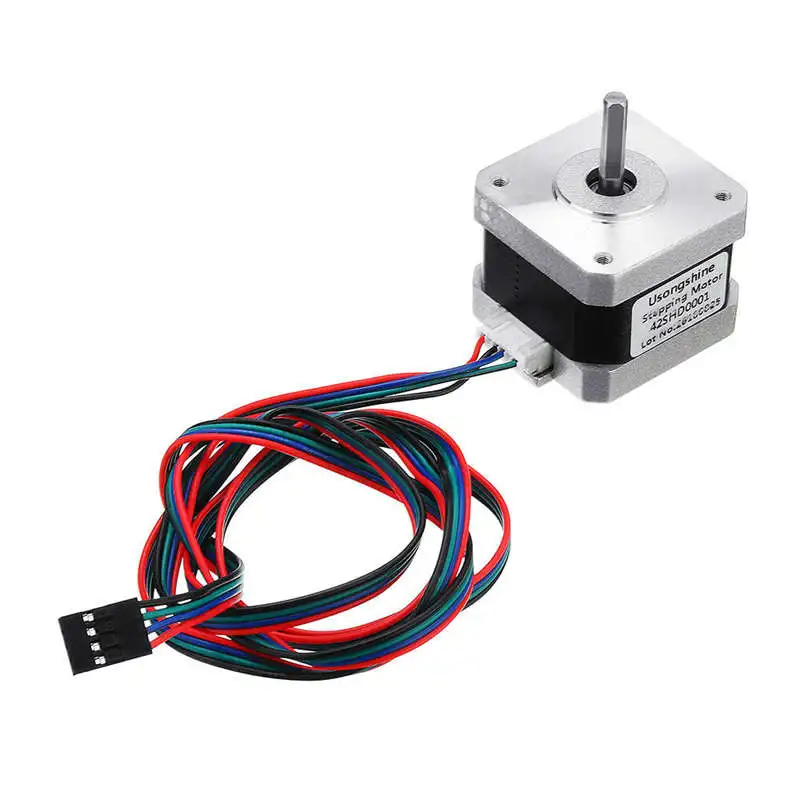 This peculiar method is the generally accepted standard for the control of CNC (Computer Numerical Control) machine tools. This programming language is called G-code. The language is peculiar, and there is no need to learn it, the translation of the model from a graphical view into machine code for moving the hot end along the axes and feeding plastic is carried out in slicer programs. I will describe them a little later, but for now I want to return to the physical part of the printers and consider what can be used to correctly turn stepper motors and get a finished model.
1. Control boards and how they operate.
For a simplified understanding of the board, it is worth dividing it into 2 categories according to their capacity. There are 8-bit and 32-bit. The first 3D printers based on REPRAP ( Replicating Rapid Prototyper - a self-replicating mechanism for rapid prototyping) were based on a common robotics board aimed at non-professional users - Arduino.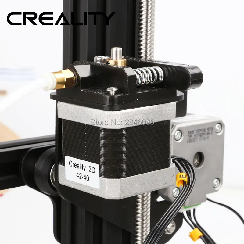 To create the firmware, we use our own free development environment - the Arduino IDE.
Arduino and Arduino-compatible boards are designed to be expanded as needed by adding new components to the device. As the most powerful, the Arduino Mega 2560 board with an 8-bit processor was taken.
To expand its capabilities, that is, control the heating of a hot table (Heat bed), hot end (Hot end), control the rotation of stepper motors, take into account the zero position using limit switches and other things, an expansion board RAMPS (RepRap Arduino Mega Pololu Shield) was developed .
Also, drivers compatible with this board (Pololu drivers) were developed to control stepper motors.
Which are inserted into the slots on the board. That is, for each stepper motor connected to the Arduino + RAMPS bundle, a driver is needed. RAMPS supports up to 5 stepper motors.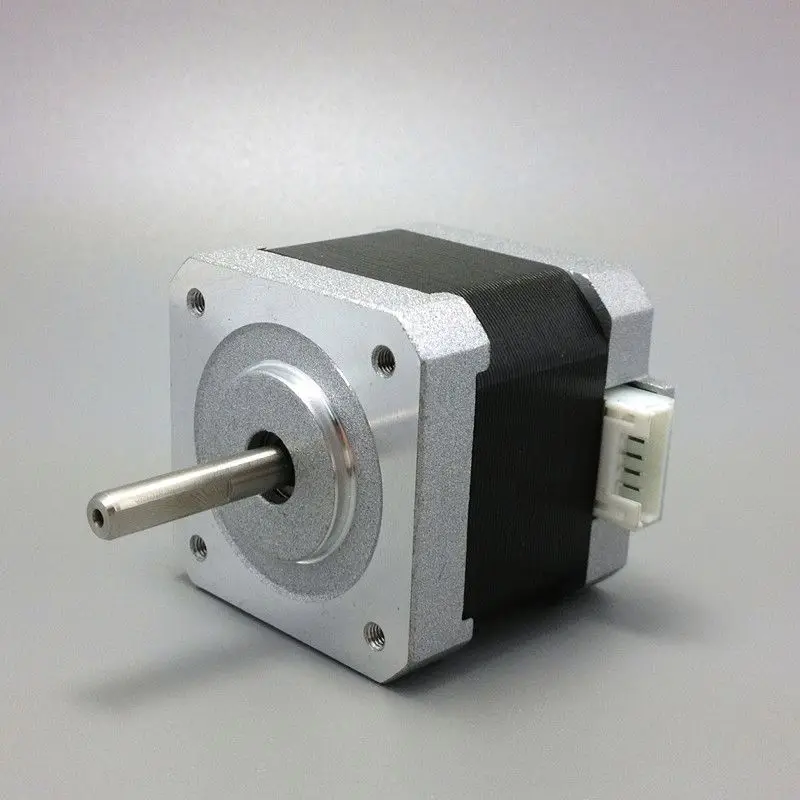
To control a stepper motor, it is necessary to adjust the motor supply voltage with a trimmer resistor. The setting is made with a multimeter in the DC voltage measurement mode. One probe touches the ground (the extreme contact on the driver labeled GND or the negative wire from the power supply), while the other touches the tuning resistor.
Next, you need to calculate the required voltage using the formula, based on the current for which the motor is designed.
Vref - voltage measurement pin for setting the current according to the formula.
Current Limit - stepper motor current.
Vref formula for A4988 varies from value of current sense resistors. These are the two black rectangles on the driver board. Usually signed R050 or R100.
Vref = Current Limit * 8 * (RS)
RS = 0.100
Vref = Current Limit * 8 * 0.100 = Current Limit / 1.25
RS = 0.050
Vref = Current Limit * 8 * 0. 050 = Current Limit / 2.5
For example for 17HS4401 : : \u003d 1.7 / 2.5 \u003d 0.68V
And by rotating the resistor we achieve this figure on the multimeter display. An important addition, in order to adjust the voltage, you must turn off the printer, and turn it on to measure.
Formulas for other types of drivers can be found in this article.
Other All-in-one boards (all on one board, without such layered designs) have similar pads under the already common Pololu drivers.
Also, to select the operating mode of the stepper motor, jumpers are made between the pads for installing stepper motors, by closing which we select one or another operating mode.
There are only 5 operating modes for the stepper motor with A4988 drivers: full step, 1/2 step, 1/4 step, 1/8 step and 1/16.
Jumpers total 3: MS0, MS1, MS2. Low - no jumper, high - installed.
It turns out that when there is not a single jumper, the motor rotates without dividing the step into microsteps, and when all 3 are installed - by 1/16.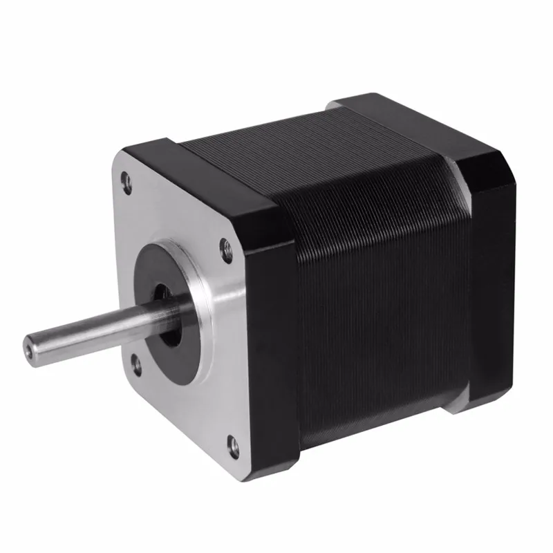
The splitting of a step into microsteps is done for the sole purpose of increasing the accuracy of movement. That is, using a 1/4 step split, we will not be able to stop in the middle between 2 and 3 microsteps. At 1/16 this is possible.
There are many drivers available that are compatible with boards used in 3D printers. Small list:
1 ) A4988.
Available in green or red.
Maximum divisor 1/16.
2 ) DRV8825.
Available in both purple and blue. Due to the lack of a normal hold mode (in a static position, but with the rotor fixed, this mode usually consumes less energy than rotation) gets very hot. Therefore, it is recommended to install a good heatsink on the chip.
Maximum divisor 1/32.
3 ) TMC2100.
There is both the original, available in stores in Germany and the US, and many Chinese copies.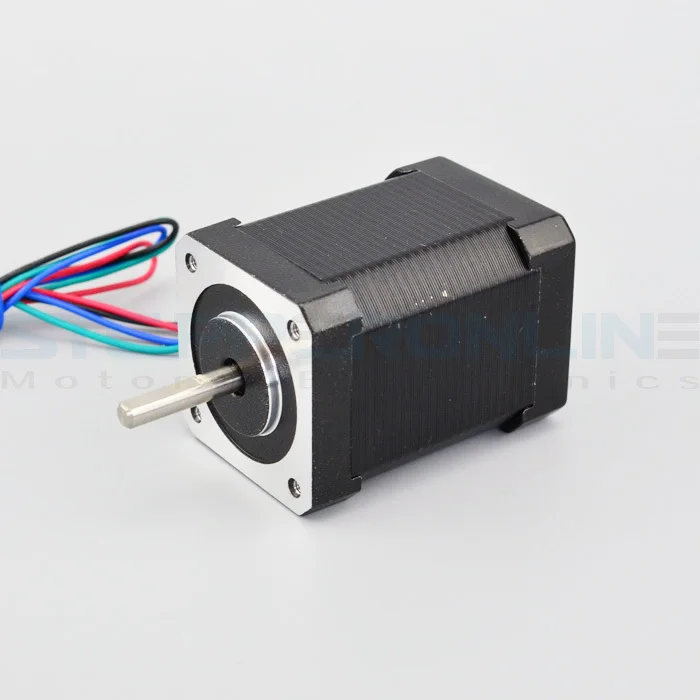
The chip is the same, made in Germany, but the binding (resistors, capacitors ...) each Chinese sculpts in his own way, so it becomes difficult to select the voltage to power the stepper motor. This driver is positioned as quiet, in which the noise and squeak of engines is minimized.
Noise comparison between A4988 and TMC2100.
But as expected, something must be sacrificed in return. It gets very hot, and when overheated, skipping steps begin and movements along the axes may be incorrect.
For the first time, the cube became a snot caterpillar for me.
As a result, you need good cooling (some Chinese neglect metallization to remove heat, since the chip is located 'on the belly') and very precise voltage regulation. There are also small tricks - it seems to have fine-tuned it, it prints small details for a month without congresses, and you put the detail for a day or two, and somewhere at the end of the print you will get a 0.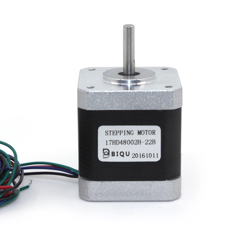 5 mm microcongress.
The driver has its own chip that interpolates the 1/16 divider to 1/256 with no load on the processor, and ensures very quiet operation.
4 ) LV8729
The most common driver is made by the Chinese company Makerbase (MKS).
Drivers feature a wide range of microstep divider adjustments. From full to 1/128. There is no internal divider, like the TMS2100.
Use with 1/64 and 1/128 with 8-bit electronics (based on AtMega 2560) is not recommended, as it requires a lot of CPU resources. Designed for installation in 32-bit boards.
5 ) SD5984.
Panucatt Devices drivers. Sold only there, the Chinese do not make such. They also support step splitting from full to 1/32. There is protection against high current and overheating. As you noticed in the photo, there are 2 'extra' pins - the drivers support voltage regulation from the outside, that is, in the firmware of the board.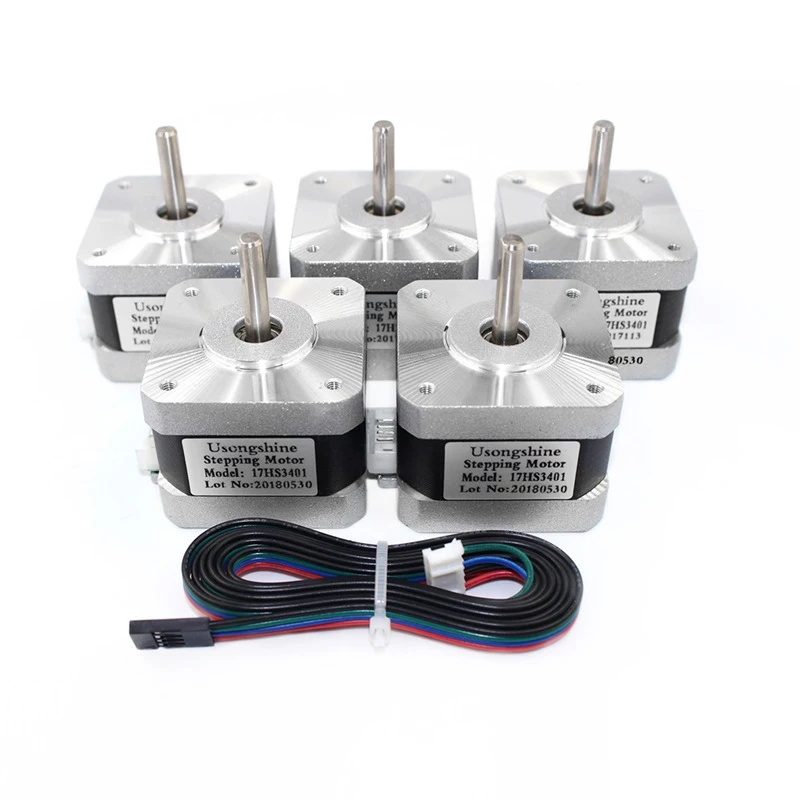 Which makes it very convenient to control and adjust the voltage.
Available in 2 versions:
1) Standard version. The platform for voltage adjustment pins is shorted, and voltage adjustment is possible as in all other drivers - by hand, in the sense of a screwdriver and a multimeter. Supported by all boards.
2) Digital adjustment. Pins are available and adjustment is done programmatically. Supported only by native controllers: Azteeg X3, X3 PRO and X5 mini V3.
6 ) SD6128
Drivers also manufactured by Panucatt Devices.
Unlike the SD6128, they have a step division up to 1/256. Also, there is protection against overheating and high current. Similarly, it is present in 2 versions: with manual voltage adjustment, and with support for software adjustment. Software adjustment is only available for Azteeg X3, X3 PRO and X5 mini V3 boards.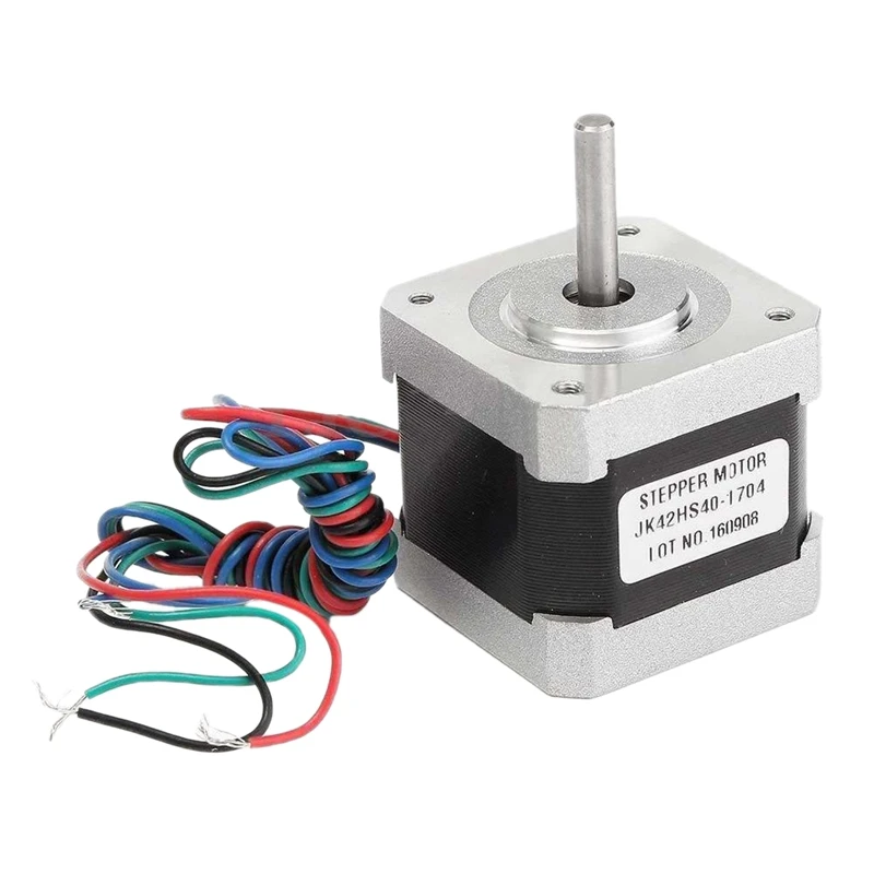
The driver is based on the THB6128 chip. The driver works in both 3.3V (32-bit boards) and 5V (8-bit boards). The divider is installed in the same way, with jumpers, in accordance with the table from the pdf description.
For installation in 8-bit boards, it is not recommended to use dividers higher than 1/64 due to possible processor overload.
7 ) SD8825.
Panucatt Devices own version, similar to the familiar DRV8825, with the only difference that there are 2 pins for voltage control on the driver. Adjustment is available only on boards of our own production: Azteeg X3, X3 PRO and X5 mini V3.
Divider 1/32.
8 ) TMC2130.
I have already described my experience of using and buying. I repeat, if there is a desire to get confused using SPI on the board, and try to adjust the voltage - please. The widespread firmware for 8-bit Marlin boards has already added a library for this driver and auto-regulation of its voltage (the current is added until an overheating error appears, then it decreases step by step, in 50mA steps), but so far there are sensible mentions of installing and I did not see the Pololu driver setup.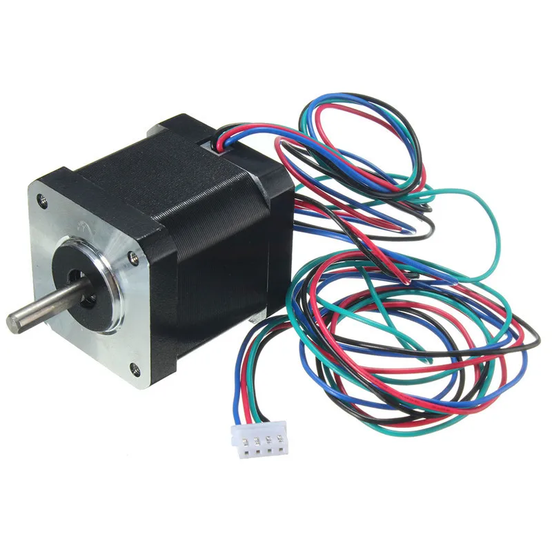 The only implementation that deserves attention is the implementation of Joseph Pryusha, on the new MK3. In his new EINSY RAMBO board, driver data is already soldered into the board, and the firmware supports voltage regulation. One of the advantages of this driver is the control of the moment on the motor rotor, that is, at the moment the stopper carriage touches, the moment on the rotor shaft increases sharply, and the board understands that the carriage has reached its maximum and there is no point in trying to move it further. Therefore, there are no limit switches.
The board, similarly to the TMC2100, has an internal divisor from 1/16 to 1/256. Switching between dividers is done by software, via the SPI interface.
Quite a few Chinese clones have appeared, in which the SPI interface is soldered, and the operation is completely similar to the TMC2100. According to a representative of Watterott, there is no difference between the TMC2100 and TMC2130 with soldered SPI.
9 ) TMC2208
New drivers from Trinamic and Watterott. The microstep division configuration is carried out via the UART interface, with such a board.
The board provides the connection of the driver through this interface via a cable to the computer's USB. Next, with the help of its own utility, the parameters are configured.
After configuring the firmware, the board can be disconnected from the driver.
Chinese clones of this board have already appeared.
I got myself one. I can draw the only conclusion - Chinese clones are much more capricious and more difficult to adjust the voltage than the originals. There were BigtreeTech TMC2100 and Makerbase TMC2100 and these blkbox TMC2208, and of course the original TMC2100. Set up the Chinese, what would be straight
, I couldn't miss a single step in a long enough print.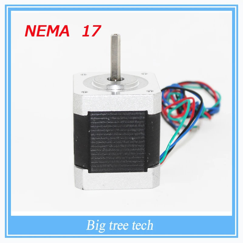 For that, the original in 5 minutes and everything is ok.
The chip has the same divisor from 1/16 to 1/256 as all other TMC2100,2130.
10 ) RAPS128
It is difficult to say who repeated whom if all stereotypes are removed. German drivers based on THB6128 (like the Panucatt Divices SD6128, according to Wiki REPRAP.org and the manufacturer's website. Judging by the description on the website of the store where they are sold, the Germans do not hesitate to install LV8729V, like the Chinese MKS LV8729.
The driver has a divisor from full step to 1/128. For 8-bit boards, it is not recommended to set the divisor above 1/32.
Very noticeable, not 1, but 2 potentiometers stand out.
The left one is for setting the voltage, and the right one is responsible for adjusting the current slope. The manufacturer recommends keeping the position of this potentiometer somewhere in the middle, from 1.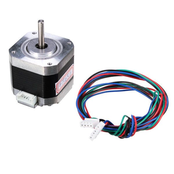 1 to 3V. In the datasheet for any driver there are tabular values \u200b\u200bfor setting the current decay.
A small digression.
I will present a small squeeze of this article , to understand the principles of operation of stepper motors and the difficulties of controlling them.
Stepper motor. How does it work and why does it need a current drop?
A stepper motor is an electromechanical device that converts electrical impulses into discrete mechanical movements.
However, stepper motors have many useful features, and most importantly - they are cheap.
Why is a stepper motor good?
- the angle of rotation of the rotor is determined by the number of pulses that are applied to the motor;
- motor provides full torque in hold mode;
- precise positioning and repeatability. Good stepper motors have an accuracy of 3-5% of the step size. This error does not accumulate from step to step;
- quick start/stop/reverse capability;
- brushless reliability, stepper motor life is actually determined by bearing life;
- single-valued dependence of the position on the input pulses provides positioning without feedback;
- the possibility of obtaining very low rotational speeds for a load attached directly to the motor shaft without an intermediate gearbox;
- quite a wide range of speeds can be covered, the speed is proportional to the frequency of the input pulses;
But not so good. ..
..
- Stepper motors have a resonance phenomenon;
- possible loss of position due to lack of feedback;
- power consumption does not decrease even without load;
- difficult to work at high speeds;
- low power density;
- relatively complex control scheme;
There are three main types of stepper motors:
- variable reluctance motors
- permanent magnet motors
- hybrid motors
You can even feel the type of motor by touch: when the shaft of a de-energized permanent magnet motor (or a hybrid one) rotates, a variable resistance to rotation is felt, the motor rotates as if by clicking. At the same time, the shaft of a de-energized variable reluctance motor rotates freely. Hybrid motors are a further development of permanent magnet motors and do not differ from them in the way they are controlled. You can also determine the type of motor by the configuration of the windings.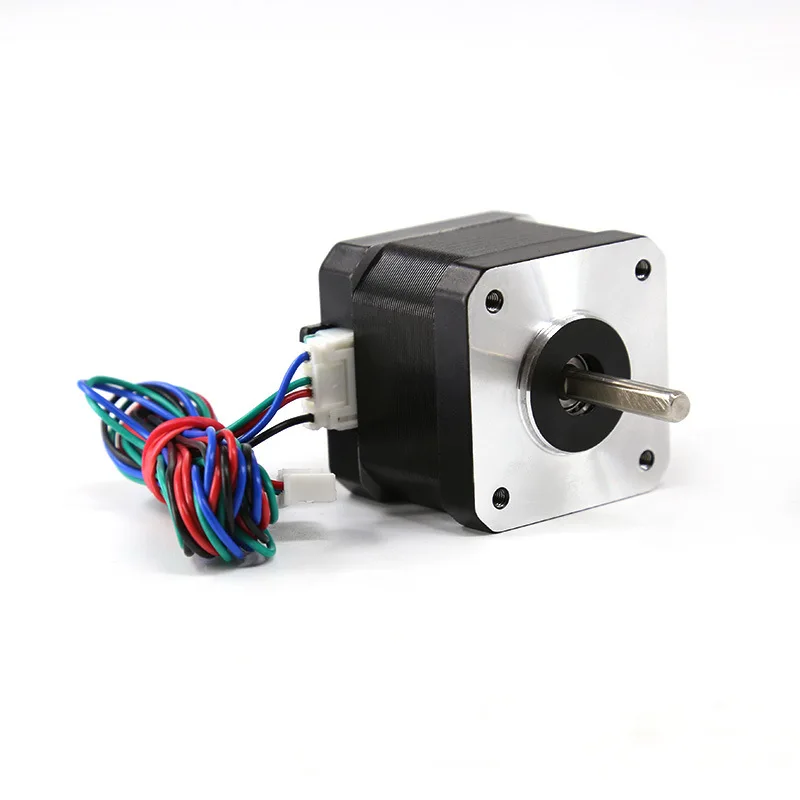 Variable reluctance motors usually have three (rarely four) windings with one common terminal. Permanent magnet motors most often have two independent windings. These windings may have taps from the middle. Sometimes permanent magnet motors have 4 separate windings.
In a stepper motor, the torque is generated by the magnetic fluxes of the stator and rotor, which are appropriately oriented relative to each other. The stator is made of high permeability material and has multiple poles. A pole can be defined as a certain area of a magnetized body where the magnetic field is concentrated. The poles have both a stator and a rotor. To reduce eddy current losses, the magnetic circuits are assembled from separate plates, similar to the core of a transformer. The torque is proportional to the magnitude of the magnetic field, which is proportional to the current in the winding and the number of turns. Thus, the torque depends on the parameters of the windings. If at least one winding of the stepper motor is energized, the rotor assumes a certain position.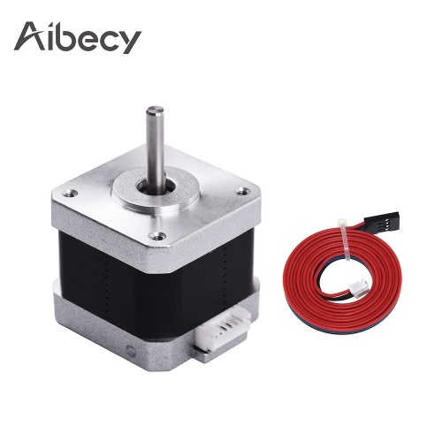 It will be in this position until the external applied moment exceeds a certain value, called the holding moment. After that, the rotor will turn and will try to take one of the following equilibrium positions.
We are interested in the hybrid motors most commonly used in 3D printers.
Hybrid motors combine the best features of variable reluctance and permanent magnet motors. The rotor of a hybrid engine has teeth arranged in an axial direction.
The rotor is divided into two parts with a permanent magnet in between. Thus, the teeth of the upper half of the rotor are the north poles, and the teeth of the lower half are the south poles. In addition, the upper and lower halves of the rotor are rotated relative to each other by half the pitch angle of the teeth. The number of pairs of rotor poles is equal to the number of teeth on one of its halves. The toothed pole pieces of the rotor, like the stator, are assembled from separate plates to reduce eddy current losses. The hybrid motor stator is also toothed, providing a large number of equivalent poles, as opposed to the main poles where the windings are located. Usually 4 main poles are used for 3.6 deg. motors and 8 main poles for 1.8- and 0.9deg. engines. The teeth of the rotor provide less resistance to the magnetic circuit at certain positions of the rotor, which improves static and dynamic torque. This is ensured by the appropriate arrangement of the teeth, when part of the rotor teeth is strictly opposite the stator teeth, and part is between them.
The rotor of a conventional 3D printer motor has 100 poles (50 pairs), the motor has 2 phases, so the total number of poles is 200, and the pitch, respectively, is 1.8 deg.
As you can see in the picture, the air gaps at the upper and lower pole pieces of the rotor are different. This is achieved by turning the pole pieces by half the pitch of the teeth. Therefore, there is another magnetic circuit that contains minimal air gaps and, as a result, has a minimal magnetic resistance.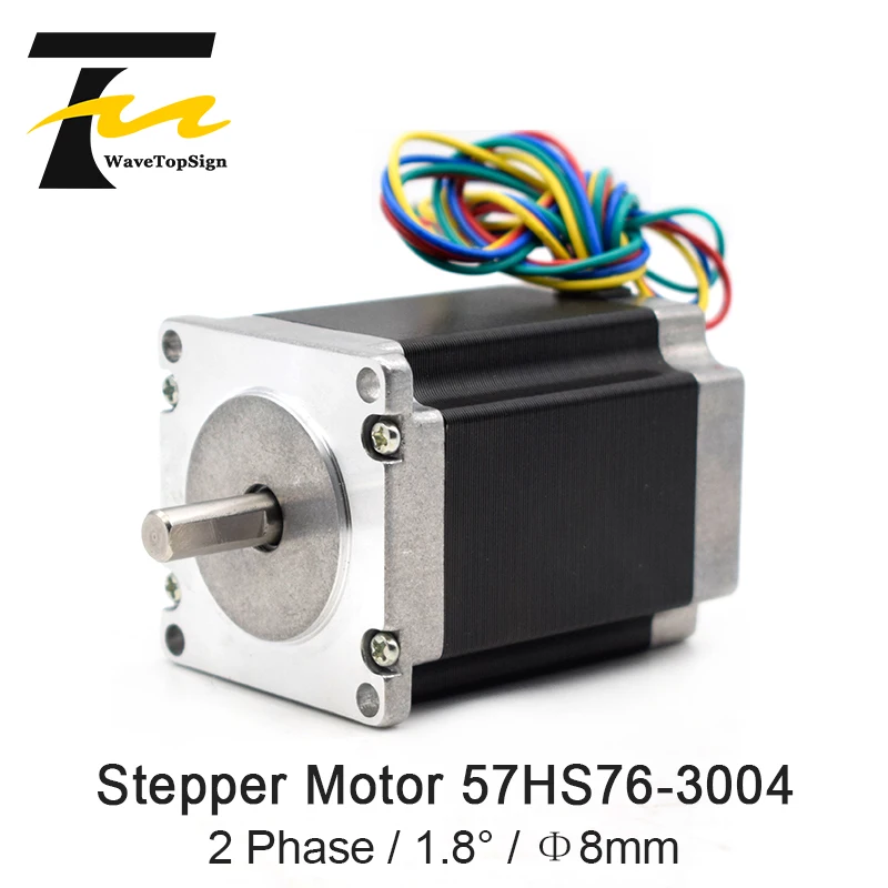 Another part of the flow closes along this circuit (shown in the figure by a dashed white line), which creates the moment. Part of the chain lies in a plane perpendicular to the figure, therefore it is not shown. In the same plane, the magnetic flux of the stator coil is created. In a hybrid engine, this flow is partially closed by the rotor pole pieces, and the permanent magnet “sees” it weakly. Therefore, unlike DC motors, the hybrid motor magnet cannot be demagnetized at any winding current.
The gap between the teeth of the rotor and the stator is very small - typically 0.1 mm. This requires high precision during assembly, so the stepper motor should not be disassembled for the sake of satisfying curiosity, otherwise its service life may end there.
To prevent the magnetic flux from closing through the shaft, which passes inside the magnet, it is made of non-magnetic steel grades. They are usually very brittle, so a shaft, especially a small diameter, should be handled with care.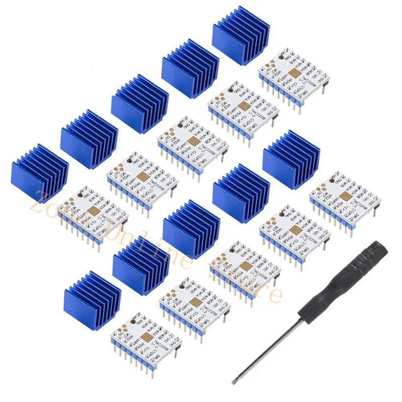
To obtain large torques, both the field created by the stator and the field of the permanent magnet must be increased. This requires a larger rotor diameter, which worsens the ratio of torque to moment of inertia. Therefore, powerful stepper motors are sometimes structurally made from several sections in the form of a whatnot. Torque and moment of inertia increase in proportion to the number of sections, and their ratio does not deteriorate.
Hybrid engines are divided into 2 types. Depending on the configuration of the windings, the motors are divided into bipolar and unipolar. A bipolar motor (in the figure below under the letter a) has one winding in each phase, which must be reversed by the driver in order to change the direction of the magnetic field. In total, the bipolar motor has two windings and, accordingly, four outputs.
The unipolar motor (b) also has one winding in each phase, but a tap is made from the middle of the winding.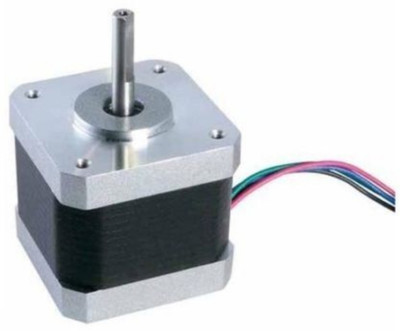 This makes it possible to change the direction of the magnetic field created by the winding by simply switching the halves of the winding. The middle terminals of the windings can be combined inside the motor, so such a motor can have 5 or 6 terminals. Sometimes unipolar motors have separate 4 windings, for this reason they are mistakenly called 4-phase motors. Each winding has separate leads, so there are 8 (c) leads in total. With an appropriate connection of the windings, such a motor can be used as a unipolar or bipolar. A unipolar motor with two windings and taps can also be used in bipolar mode if the taps are left unconnected. In any case, the winding current should be chosen so as not to exceed the maximum power dissipation.
So which one is better?
When comparing bipolar and unipolar motors, the former has a higher power density. For the same size, bipolar motors provide more torque.
The torque generated by the stepper motor is proportional to the magnitude of the magnetic field generated by the stator windings.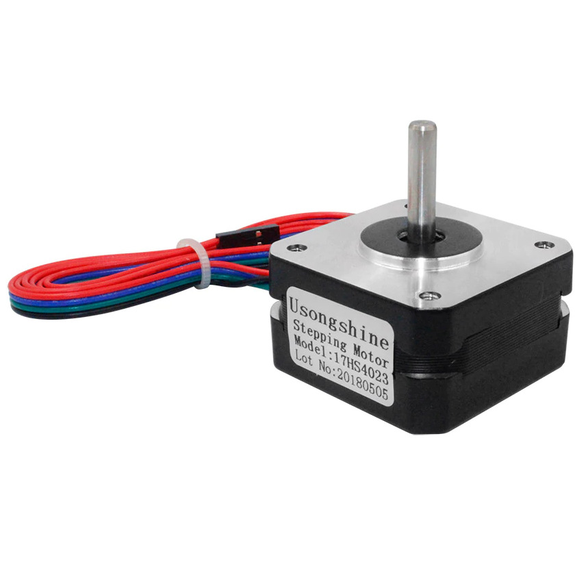 The most important is the limitation on motor heating due to ohmic losses in the windings. Just this fact demonstrates one of the advantages of bipolar motors. In a unipolar motor, only half of the windings are used at any given time. The other half simply takes up space in the core window, which forces the windings to be made with smaller diameter wire. At the same time, all windings are always working in a bipolar motor, i.e. their use is optimal. In such a motor, the cross section of the individual windings is twice as large, and the ohmic resistance is, accordingly, half as much. This makes it possible to increase the current by the root of two times with the same losses, which gives a gain in torque of about 40%. If increased torque is not required, a unipolar motor allows you to reduce the size or simply work with less loss. In practice, however, unipolar motors are often used, since they require much simpler winding control circuits.
How to control a stepper motor?
There are several ways to control a stepper motor. I will not paint everything, since they refer to full-step or half-step modes of operation. We are interested in the microstep mode. With this control method, the current in the phases must be changed in small steps, thus ensuring the splitting of a half step into even smaller microsteps (An important resource is the processor frequency, i.e. with what frequency it can send a STEP signal to move the driver). When two phases are switched on at the same time, but their currents are not equal, then the equilibrium position of the rotor will not lie in the middle of the step, but in a different place, determined by the ratio of the phase currents. By changing the ratio, it is possible to provide a certain number of microsteps within one step. To implement the microstep mode, more complex drivers are required that allow you to set the current in the windings with the required ratio. The half-stepping mode is a special case of the microstepping mode, but it does not require the formation of a stepped coil supply current, therefore it is often implemented.
Microstepping is achieved by making the stator field turn more smoothly than full or half stepping. The result is less vibration and virtually silent operation down to zero frequency. A smaller pitch angle can provide more accurate positioning. There are many different microstepping modes, with step sizes ranging from 1/3 of a full step to 1/512. The stepper motor is a synchronous motor. This means that the equilibrium position of the stationary rotor coincides with the direction of the stator magnetic field. When the stator field rotates, the rotor also rotates, trying to take a new equilibrium position.
To obtain the desired direction of the magnetic field, it is necessary to choose not only the correct direction of the currents in the coils, but also the correct ratio of these currents.
The displacement of the balance point of the rotor indicates that the rotor can be fixed in any arbitrary position. To do this, you just need to correctly set the ratio of currents in the phases. It is this fact that is used in the implementation of the microstep mode.
Microstepping results in a smoother rotor at low frequencies. To achieve high speeds in the microstep mode, a high repetition rate of microsteps is required, which cannot always be provided by the control microcontroller. It is because of this that the transition from 8-bit electronics to 32-bit occurs, since delta printers use the movement of 3 motors at once to move along one axis.
With each step, the rotor does not immediately stop in the new equilibrium position, but performs damped oscillations around the equilibrium position. The settling time depends on the characteristics of the load and the driver circuit. Generally, fluctuations are undesirable. You can get rid of this phenomenon using microstepping mode. Below are shown the movements of the rotor when operating in full stepping and microstepping modes.
It can be seen that spikes and fluctuations are observed in the full-stepping mode, while they are not observed in the microstepping mode.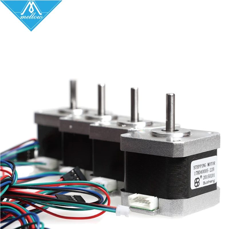 However, even in this mode, the rotor position graph differs from a straight line. This error is explained by the geometry error of the motor parts and can be reduced by performing calibration and subsequent compensation by adjusting the phase currents.
When the rotor rotates, the motor has dead zones that limit positioning accuracy.
The figure shows the dependence of torque on the angle of rotation of the rotor.
The presence of dead zones is very important for microstepping. If, for example, there are dead zones with a value of d, then a microstep of less than d will not move the rotor at all.
When the motor is running under load, there is always some shift between the angular position of the rotor and the orientation of the stator magnetic field. Especially unfavorable is the situation when the motor starts to decelerate and the load torque is reversed. It should be noted that lag or lead refers only to the position, not to the speed.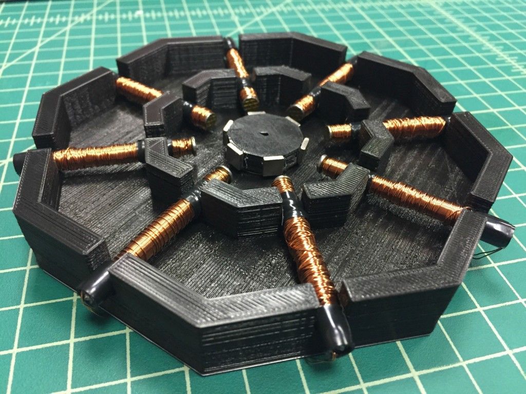 In any case, as long as the motor is not out of sync, this lag or lead cannot exceed two full steps. This is a very pleasant fact.
Each time the stepper motor takes a step, the rotor rotates S radians. In this case, the minimum moment occurs when the rotor is between adjacent equilibrium positions.
This torque is called the operating torque, it means what is the largest torque that the motor can overcome when rotating at low speed. If the motor is stepping with two energized windings, then the operating torque is equal to the holding torque for one energized winding.
The drive parameters depend on the characteristics of the load. In addition to friction, a real load has inertia. Inertia prevents speed change and requires high acceleration and deceleration torques from the motor, limiting maximum acceleration. On the other hand, increasing the load inertia increases the speed stability.
When designing stepper motor drivers, it must be taken into account that the motor windings are inductive.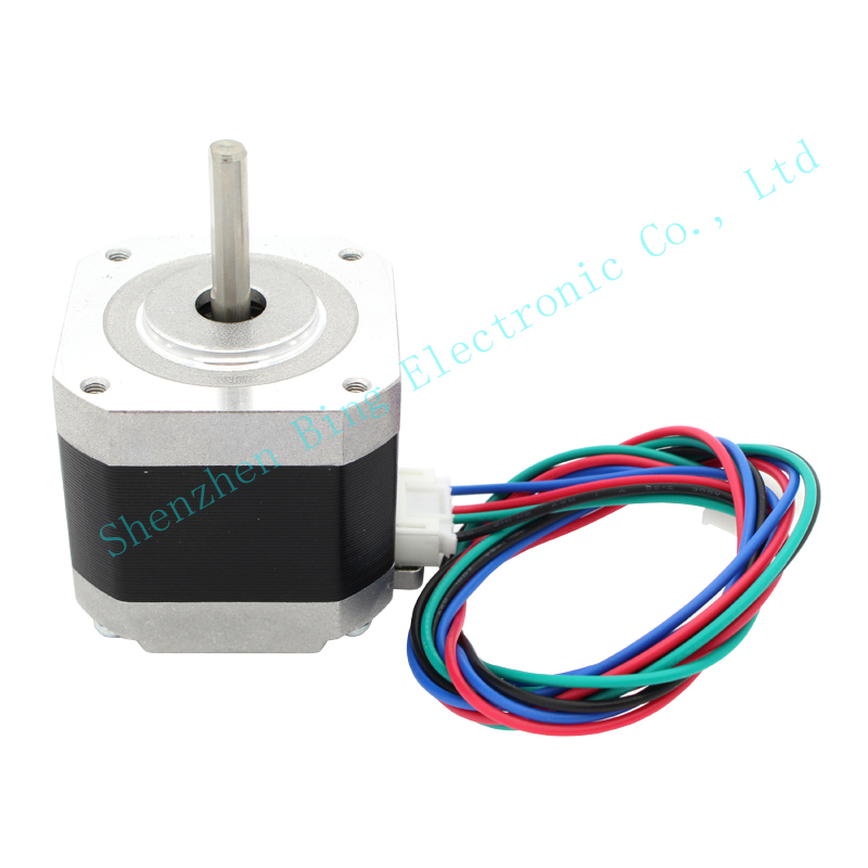 This inductance determines the rise and fall time of the current. Therefore, if a square wave voltage is applied to the winding, the current waveform will not be square wave. At low speeds (a), the rise and fall times of the current do not have much effect on the torque, but at high speeds the torque drops. This is due to the fact that at high speeds, the current in the motor windings does not have time to reach the nominal value (b).
In order for the torque to drop as little as possible, it is necessary to ensure a high rate of current rise in the motor windings, which is achieved by using special power circuits.
The behavior of the torque with an increase in the switching frequency of the phases is approximately the following: starting from a certain cutoff frequency, the torque monotonically decreases. Typically, two torque versus speed curves are given for a stepper motor.
The inner curve (start curve) shows at what maximum friction torque for a given speed the stepper motor can start.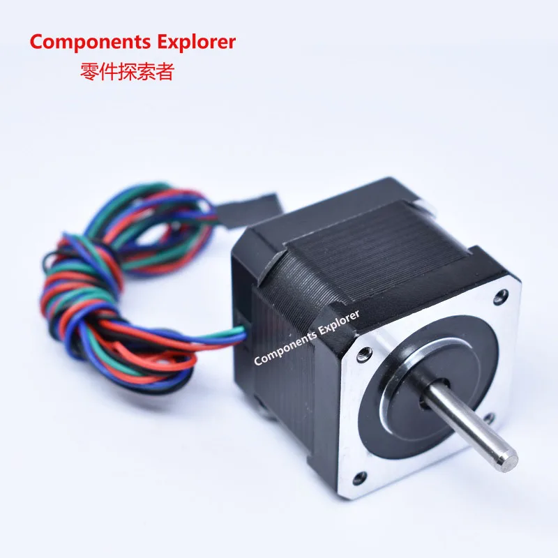 This curve intersects the velocity axis at a point called the maximum start frequency or throttle response frequency. It defines the maximum speed at which an unloaded motor can start.
The outer curve (acceleration curve) indicates at what maximum friction torque for a given speed the stepper motor is able to maintain rotation without skipping steps. This curve intersects the velocity axis at the point of maximum acceleration frequency. It shows the maximum speed for a given motor without load. The region that lies between the curves is called the acceleration region.
In order to operate at high speed from the acceleration area, it is necessary to start at low speed from the start area and then accelerate. When stopping, you need to act in the reverse order: first perform braking, and only after entering the start area, you can stop the supply of control pulses. Otherwise there will be a loss of synchronism and the position of the rotor will be lost.
It should be noted that the continuous operation of the stepper motor at high speed is not always possible due to the heating of the rotor.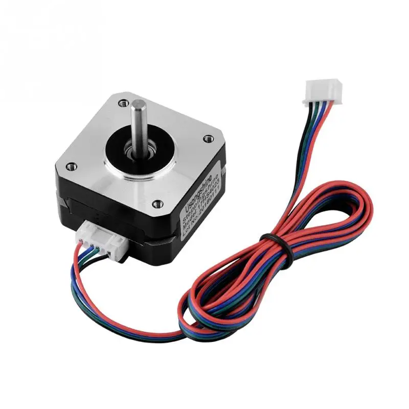
When accelerating or decelerating, it is important to correctly select the rate of change of speed and maximum acceleration. The acceleration should be the smaller, the higher the inertia of the load. The criterion for the correct choice of the acceleration mode is the acceleration to the desired speed for a specific load in the minimum time. Most often, acceleration and deceleration with constant acceleration are used.
The implementation of the law, according to which the motor will be accelerated or decelerated, is usually performed by the program control microcontroller, since it is the microcontroller that is usually the source of the clock frequency for the stepper motor driver. To generate a clock frequency, it is convenient to use a hardware timer, which is included in the same Arduino processor - Atmega2560. When the motor rotates at a constant speed, it is enough to load the timer with a constant value of the step repetition period (step duration). If the engine is accelerating or decelerating, this period changes with each new step. When accelerating or decelerating at constant acceleration, the frequency of repetition of steps should change linearly, respectively, the value of the period that must be loaded into the timer should change according to the hyperbolic law.
Resonance
Stepper motors have an unwanted effect called resonance. The effect manifests itself in the form of a sudden drop in torque at certain speeds. This can result in skipped steps and loss of synchronization. The effect is manifested if the step frequency coincides with the natural resonant frequency of the motor rotor.
When the motor takes a step, the rotor does not immediately settle into a new position, but makes damped oscillations. The fact is that the system rotor - magnetic field - stator works like a spring pendulum, the oscillation frequency of which depends on the moment of inertia of the rotor (plus the load) and the magnitude of the magnetic field.
The resonant frequency is determined by the moment of inertia of the motor rotor itself and the moment of inertia of the load on the motor shaft.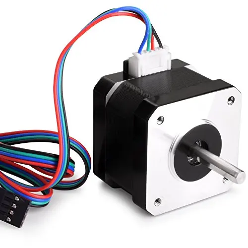 Therefore, the rotor resonant frequency of an unloaded motor, which is given among the parameters, is of little practical value, since any load connected to the motor will change this frequency.
When non-micro stepping is used, the main cause of oscillation is the intermittent rotation of the rotor. When a step is taken, some energy is imparted to the rotor by impetus. This impulse excites vibrations. The energy that is imparted to the rotor in half step mode is about 30% of the energy of a full step. Therefore, in the half-step mode, the oscillation amplitude is much smaller. In microstepping mode with 1/32 of the main step, only about 0.1% of the energy of a full step is reported at each microstep. Therefore, in the microstep mode, the resonance phenomenon is almost imperceptible.
Current reversal methods
Stepper motor operation requires reversal of the magnetic field independently for each phase. Changing the direction of the magnetic field can be done in different ways. In unipolar motors, the windings are center tapped or there are two separate windings for each phase. The direction of the magnetic field is changed by switching half windings or whole windings. In this case, only two simple switches A and B are required for each phase.
In bipolar motors, the direction is changed by reversing the polarity of the winding leads. Polarity reversal requires a full H-bridge (figure below). Key management should be carried out by a logic circuit that implements the desired operation algorithm. It is assumed that the power supply of the circuits has a nominal voltage for the motor windings.
After the inductance is disconnected from the power supply, the current cannot stop immediately. There is an EMF (electromotive force) of self-induction, which has the direction opposite to the power source.
To adjust the torque, you need to adjust the current in the windings. In any case, the current must be limited so as not to exceed the power dissipation on the ohmic resistance of the windings.