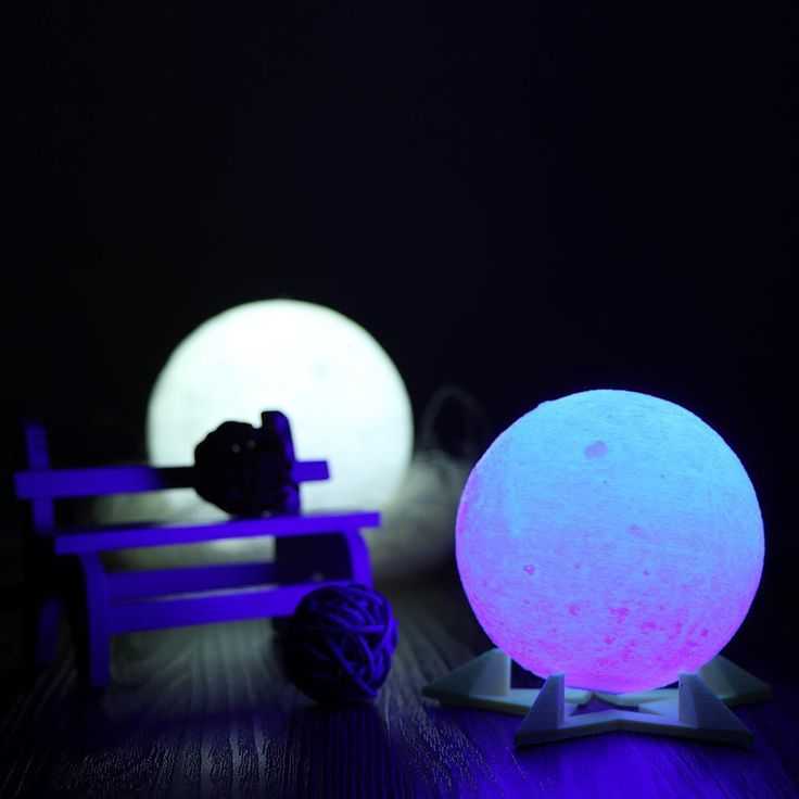
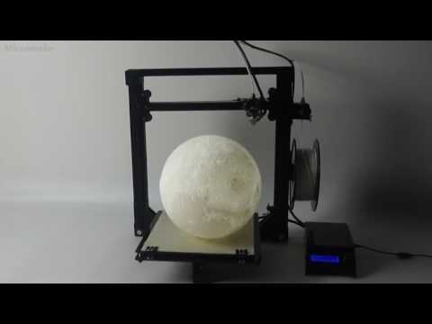
3D printing moonlight
3d Moon Lamp - Etsy.de
Etsy is no longer supporting older versions of your web browser in order to ensure that user data remains secure. Please update to the latest version.
Take full advantage of our site features by enabling JavaScript.
Find something memorable, join a community doing good.
( 464 relevant results, with Ads Sellers looking to grow their business and reach more interested buyers can use Etsy’s advertising platform to promote their items. You’ll see ad results based on factors like relevancy, and the amount sellers pay per click. Learn more. )
3D Printing Moon Lamp Moonlight USB LED Night Lunar Light
Etsy is no longer supporting older versions of your web browser in order to ensure that user data remains secure. Please update to the latest version.
Take full advantage of our site features by enabling JavaScript.
Click to zoom
58 sales |
4 out of 5 stars from €23.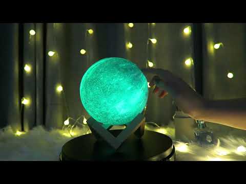 02
02
Loading
VAT included (where applicable), plus shipping
Diameter
Select a diameter 8 cm (€23.02) 10 cm (€32.05) 12 cm (€44.87) 18 cm (€51.28)
Please select a diameter
Quantity
12345678910111213141516171819202122232425262728293031323334353637383940414243444546474849505152535455565758596061626364656667686970717273747576777879808182838485868788899091929394
Explore related categories & searches
Listed on Sep 23, 2022
36 favorites
Report this item to Etsy
Choose a reason…There’s a problem with my orderIt uses my intellectual property without permissionI don’t think it meets Etsy’s policiesChoose a reason…
The first thing you should do is contact the seller directly.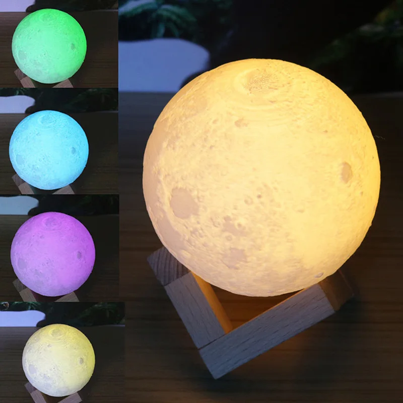
If you’ve already done that, your item hasn’t arrived, or it’s not as described, you can report that to Etsy by opening a case.
Report a problem with an order
We take intellectual property concerns very seriously, but many of these problems can be resolved directly by the parties involved. We suggest contacting the seller directly to respectfully share your concerns.
If you’d like to file an allegation of infringement, you’ll need to follow the process described in our Copyright and Intellectual Property Policy.
Review how we define handmade, vintage and supplies
See a list of prohibited items and materials
Read our mature content policy
The item for sale is…not handmade
not vintage (20+ years)
not craft supplies
prohibited or that use prohibited materials
not properly labeled as mature content
Please choose a reason
Tell us more about how this item violates our policies.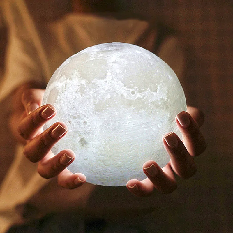 Tell us more about how this item violates our policies.
How to create your own Moon / Sudo Null IT News
This article shows you how to make a 3D model of the Moon from scratch. It would seem, Why create a model of the Moon yourself, if you can buy it? If only because when you make a model of the Moon yourself, you can set the desired parameters, for example, the dimensions and thickness of the shell, image resolution, rotation limits, the position of the cutting plane, you can make a hole for the lamp, and so on. Let us proceed to the creation of our own moon.
A variety of 3D models of the Moon can be found on the Internet. Some can be purchased from online stores, others can be downloaded as files and printed on a 3D printer. Finished models can be divided into 2 categories:
-
The surface of the moon is drawn in detail and with high quality, but if a light source is placed in the model, its details are not highlighted from the inside.
-
Surface details are well drawn when illuminated from the inside, but without illumination they are not visible.
Step 1: Draw details
Details do not light up from the inside when a light source is placed insideDetails are drawn well when illuminated from the inside
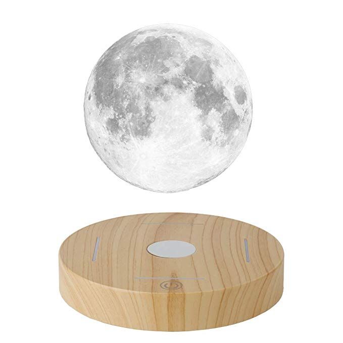
If you do not have a 3D printer, you can buy a lamp like Moon Lamp on the Internet.
Step 2: Prepare the software
Below is a list of the software involved. After familiarizing yourself with the technique, you will be able to do the same thing as I did with ordinary tools.
Modeling Tools
Download my custom version of Banate CAD from GitHub .
Banate CAD is written in Lua, so install Lua for Windows to run scripts on Windows.
STL Editing Tools
Meshmixer
Step 3 Preparing Materials
Plastic for Printing
The images above show PLA products.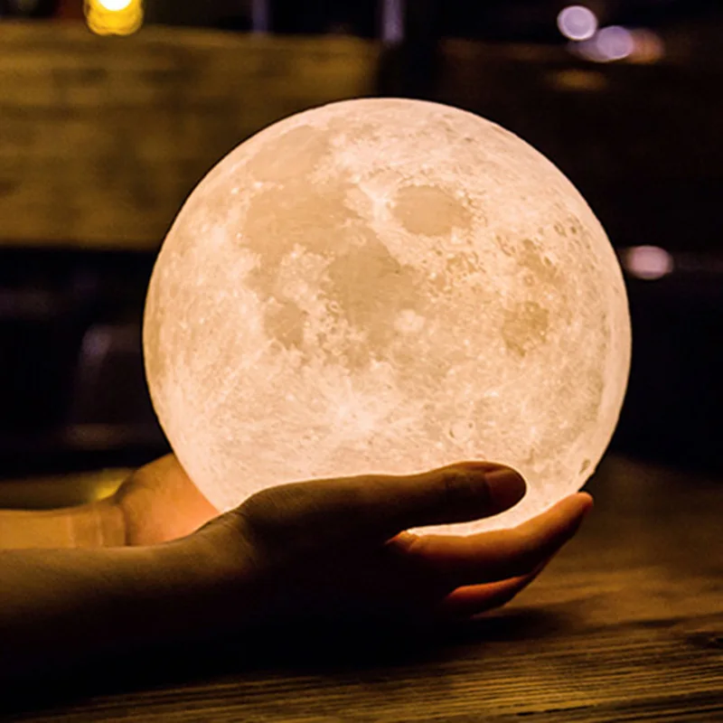 Products resulting from 3D printing using different types of white PLA plastic may have different shades. The plastic supplier claims that option B is the best, but that, alas, is stuck in my printer.
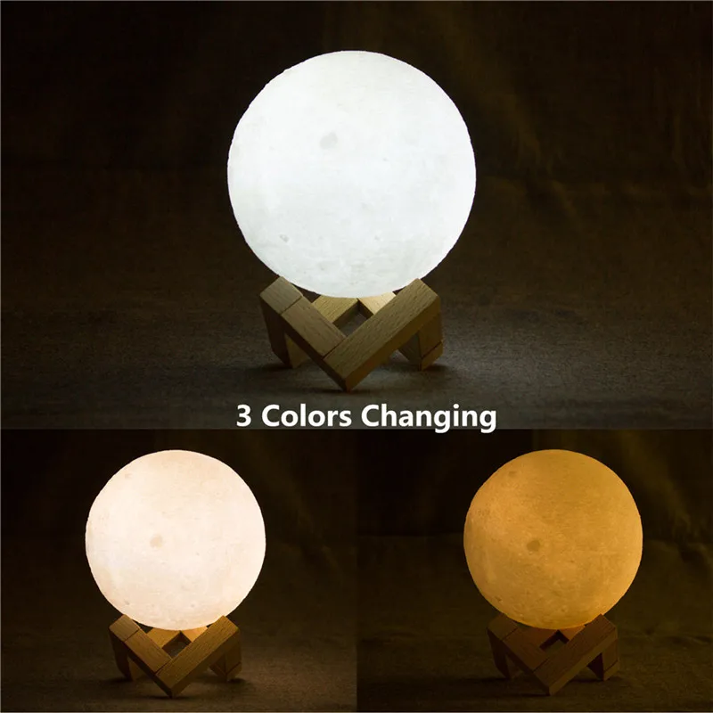
Light source
The moon model can be illuminated in different ways, the light source can be powered by batteries, mains, and so on. The size of the model also affects the choice of light source. There are a lot of options, and if we start discussing them here, we will deviate from the topic of printing. It is enough to understand that there are a lot of options. I want to note that the warm white light of the source is more pleasing to the eye.
Matte Spray Paint
Most PLA models are highly reflective, so I recommend a matte finish. Matte spray paint will easily solve the problem.
Step 4. Images of the Moon
Two images of the Moon are required for the simulation. They are located in the BanteCAD/Examples folder. I reduced the resolution to 720x360, it should be enough for the model.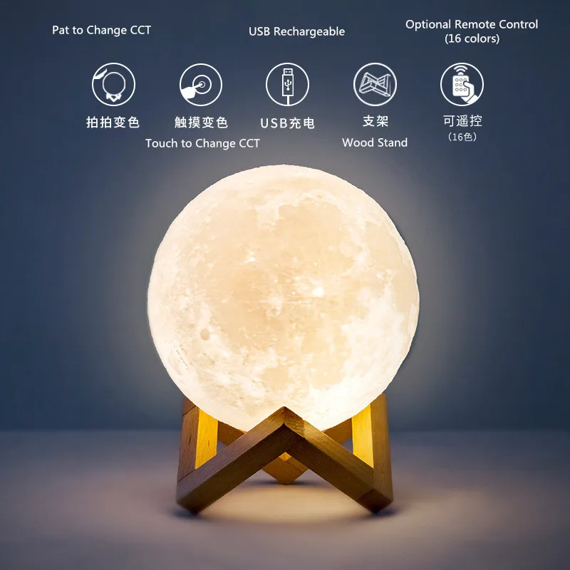 If necessary, search for higher resolution images online.
Bump map
There is a special map for surface modeling, usually called a bump map. The shade of gray indicates the height of the corresponding point on the sphere. Having a bump map, you can accurately display all the details of the surface on the model. However, if you compare the bump map with the moon in the sky, you will notice that they are different from each other.
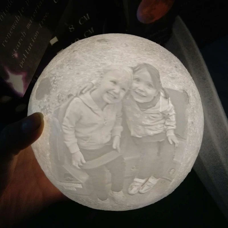
Visual map
Details of the real moon are not only different heights at different points. Color is also important. Naturally, we can instruct the printer to print different colors, but, fortunately, we see the real moon in grayscale. To allow light to pass through the model at different intensities, you can print the model with different wall thicknesses and superimpose a grayscale image on the model. To adjust the wall thickness of the model, we need a visual map of the moon.
Post-processing
-
Lunar surface map is a regular bump map.
 I need to take into account the internal thickness, so using the Level function (Level) I shift the value to the right (a brighter image will be displayed on the bump map).
 -
Inner map of the Moon is the shape of the inner surface of the model. From this map, we determine the thickness at each point of the surface, that is, the desired shade of gray. This map is built from a visual map, which in turn has thickness settings based on a bump map applied to it. Or, to use another calculation method, by subtracting the bump map from the inverted visual map.
Adjustable Parameters
-
If you lower the bump map level, the elevations on the surface will be smaller, and the sag will decrease, but the surface details will have to be distributed differently.
-
If you move the level of the visual map to the left, the shell will become thicker, and vice versa. In this case, it must be remembered that the level should not be shifted too far to the right.
 The cladding must be at least 0.4 mm thick (if a 0.4 mm extruder nozzle is used), otherwise the cladding must be manually punched.
 -
The range of the light gray scale depends on the level range of the visual map.
Attached files: moon.xcf
Step 5: Control the layer thickness above. If the shell is thinner than it is possible to print, the printer simply will not print anything, holes may even form on the surface in unexpected places. You can fix it like this.
-
Open the STL file generated by BanateCAD with Meshmixer.
-
Delete the inner surface model.
-
Run the Edit command.
-
Select the Hollow command.
-
Set thickness to 0.5mm (for extruder size 0.4mm).
-
Run the Hollow command again.
-
Accept the changes, now the thickness of the shell of the lunar surface is 0.5 mm.
-
Rotation and cutting of the plane are carried out in the same way as in the settings of the lunar shell.
-
Export the STL file.
-
Open the moon shell STL file in Microsoft 3d Builder.
-
Repair any defects.
-
Open the STL file of the lunar surface with a shell thickness of 0.5 mm.
-
Repair object defects.
-
Select the entire object.
-
Accept the changes, now the thickness of the lunar shell is 0.5 mm.
-
Export the STL file.
Step 6 Modeling - BanateCAD
BanateCAD can model a 3D shape from a bump map. In the examples folder, I posted the corresponding script. It reads a map of the surface and an internal map of the moon, and then models both shapes. The following are the steps for modeling with BanateCAD:
-
Open the BanateCAD.wlua file.
-
On the File menu, choose Open.
-
Open the file moonlamp.lua in the Examples folder.
-
Optional: change parameters.
-
From the Compile menu, choose Compile and Render.
-
After a while, the 3D model will appear.
-
From the File menu, choose Export -> Export STL.
-
Enter a name for the STL file and click the save button.
Configurable Parameters
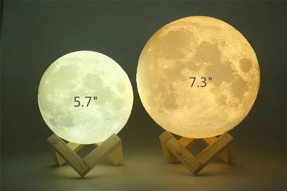
Output sphere diameter in inches, bump map and internal map are generated from this parameter:
local outputSize = 3 -- inches
Surface height factor:
local outputSize = 3 -- inches
The resolution must not be greater than the resolution of the PNG image:
USteps = 720, WSteps = 360,
Step 7: Create a Shell – Meshmixer
Based on the shapes made in BanateCAD, we can create a shell by subtracting the surface of the inner shape from the shape.
The following describes the steps to create a wrapper with Meshmixer:
-
Open the exported STL file with Meshmixer.
-
Wait for the download to complete.
-
Select both models in the Object Browser.
-
On the left toolbar, select Edit, then select Boolean Difference.
-
Wait for the calculation to complete.
-
Select Accept.
-
Wait for the calculation to complete.
-
Leave one model in the Object Browser, this will be the lunar shell.
-
Save the file.
Step 8. Modify and output the model - Meshmixer
Before 3D printing, you can configure any parameters. The options are:
-
If you want to put a model of the moon on your desktop, I suggest that the z-axis rotates from -45 to -60 degrees, so the moon will be directed towards you in its usual direction.
-
If you want to hang the moon model from the ceiling, I suggest that the z-axis rotate 120 to 135 degrees for the same reason as above.
-
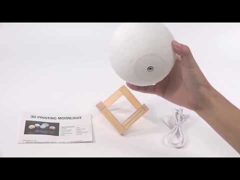
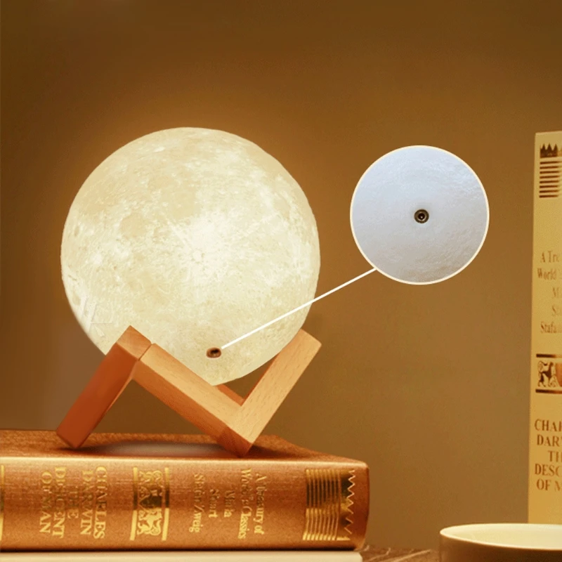
If you want to install a backlight inside, do not forget to make a hole for the wire (if you have difficulty printing a hole on a 3D printer, you can, like me, just drill a hole after printing with a drill.
-
90% percent The cutaway moons are flat, so you can hide the seams and print it easily without sagging.0003
When finished, export the STL file for printing.
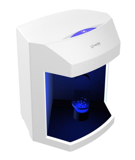
Step 9: 3D Print
Open the object in the 3D Slicer, make sure there are no holes in the shell, and start printing.
If the moon needs to be perfect, you can skip the previous step with cutting the plane and turn on the support option. But, in my opinion, removing the remnants of the caliper is quite difficult.
If the previous step was difficult for you and you could not print the STL file, use my file.
Assemble the top, light source and bottom together.
Step 10: Coating the Surface with Matte Paint
Most PLA 3D prints are highly reflective, so I recommend coating the resulting surface with Matte Paint. Now I'm trying to print a larger diameter moon lamp - 110mm, which is the largest size that can be printed with the Robo C2 printer. One printout will take tens of hours.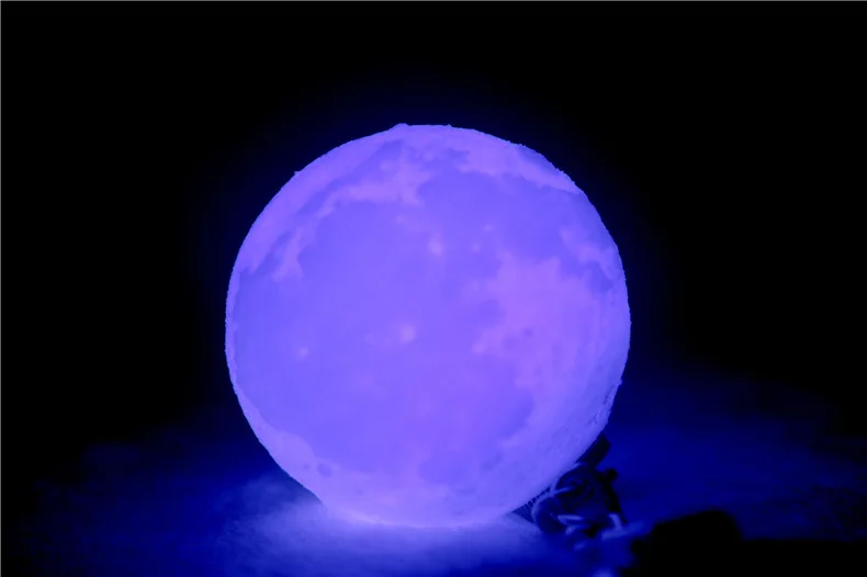 I want a moon with these parameters:
local r = 52 local h = 3
Final!
You did it! Now you can brag to the familiar results of your work or just give the finished model to your friends!
Learn how to pump in other specialties or master them from scratch:
-
Profession Data Scientist
-
Profession Data Analyst
-
Course on Data Engineering
0011 Data Analytics Course DevOps Course Little Known Facts About the History of Computer Graphics / Software patience. It is impossible to master this science with a "swoop"; this requires a long preparation. Through trial and error, after reading a lot of educational literature, after many tedious waiting for the rendering of the final scene, the insight finally comes: “So this is how it should have been done!”.
Like an athlete honing his skills on sports equipment, a computer graphics designer uses the same template constructions over and over again, which help him understand the intricacies of working with the program. Pictures and models familiar to him have been used for testing various functions of the 3D editor for so long that they seem to be quite ordinary tools. Meanwhile, many of them are not at all similar to the "standard" means. A teapot model, a 3D monkey head and other strange things - where did they come from?
Many people think that the presence in programs for developing three-dimensional graphics of such unusual models as Suzanne or Teapot is a brilliant find of developers. Indeed, unlike the correct simple objects such as a sphere, cylinder, cube or cone, models with unusual geometry look more natural. Their more complex shape allows you to quickly detect lighting and material imperfections. With these objects it is very convenient to experiment and practice modeling.
⇡#The difficult life of a simple teapot
The fate of some things is sometimes very unusual. When Martin Newell and his wife Sandra purchased a teapot from a Salt Lake City department store in 1974, they never imagined that the whole world would literally know about this thing in the future.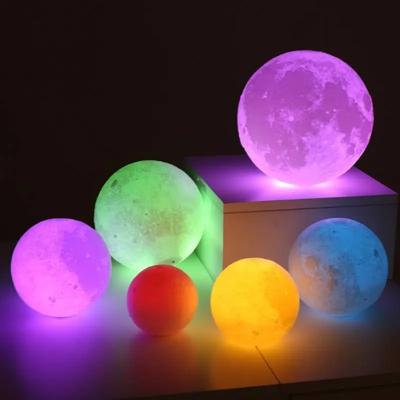
Martin Newell - the creator of the most popular 3D teapot
This was the most common ceramic teapot produced by the German company Melitta. Very simple shape - slightly rounded, with a lid. It didn't even have any design or pattern on it, just a sleek white teapot.
Newell worked on rendering algorithms for a graphics editor at the University of Utah. Hence the name of the teapot came from, it became known as the “Utah teapot”. It is interesting that initially the model of the teapot was accompanied by a set of cups and teaspoons. It looked like this.
Then the models of the tea set were confused, and only one teapot remained. The most attentive users have probably noticed that in comparison with the teapot from the 3ds max program, the proportions of the original Utah teapot are somewhat different.
3D prototype of the most famous teapot
That's right - the original object is slightly higher than the computer model. Why is that? The "parents" of the first computer model themselves are confused in their explanations.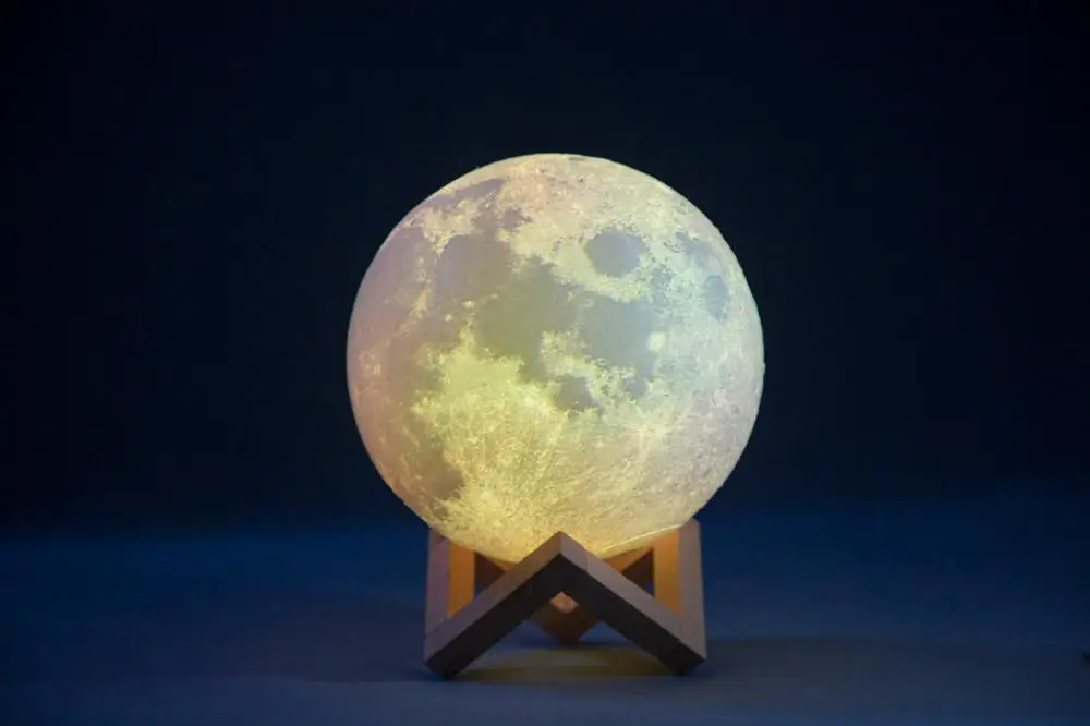 Most likely, the reason is that the framebuffer on the computer that Newell worked with had non-square pixels. Instead of distorting the image, Martin asked his colleague Jim Blinn to adjust the scale of the model to eliminate stretched deformations. Jim himself claims that they just liked the vertically scaled shape of the teapot, which they used in a demonstration in their laboratory.
This image is a unique sketch scan made by Martin Newell. As you can see, the body of the teapot on this leaf has a 4x3 aspect ratio of the base.
The teapot has become a favorite object for 3D developers. Somehow imperceptibly, they began to use it wherever possible. For example, the Commodore CBM computers that were sold in the early 1980s had the Grafikdemo demo program installed. Running it, the user could see the frame of the teapot on the screen. This base could be rotated using the keyboard, viewing from all sides. Such simple manipulations were supposed to make a strong impression on users and persuade a potential buyer to an expensive purchase.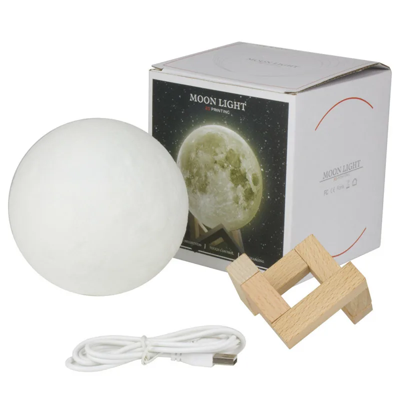
The teapot has also been seen in the popular 3Dpipes ("Pipeline") screensaver from Windows.
And now and then he appeared in various three-dimensional animations - for example, in the famous Pixar film "Toy Story" (Toy Story), where the main character drinks tea just from Newell's teapot.
Even the cartoonish Homer Simpson in one of the episodes of The Simpsons series suddenly acquired a third dimension, and Utah teapot immediately got into the frame (for fans - the sixth episode of the seventh season of Treehouse of Horror VI).
And Utah's teapot (after a little editing, he changed the shape) was in the frame when viewing another Pixar film - "Monsters Inc." (Monsters Inc.).
By the way, Pixar also has a funny tradition. Every year at the next Siggraph show, they give away souvenir Utah teapots - walking toys that advertise the RenderMan rendering engine. Usually these teapots are packed in a tea box. A wonderful souvenir of the exhibition for a 3D lover.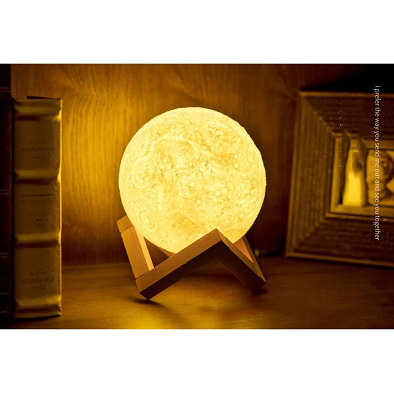
The three-dimensional model of the teapot has become the hallmark of one of the most popular 3D editors - Autodesk 3ds max. In this program, any user can easily create a teapot, even someone who has never been involved in three-dimensional modeling.
Usually ceramic dishes do not last long. But this rule does not work in the case of Newell's teapot. Not only is it still in excellent condition, but it has also passed, so to speak, into the public domain. The owner donated it to the Boston Computer Museum, where it remained until 1990 years. This exhibit can now be found at the Computer History Museum in Mountain View, California.
From time to time, the famous teapot travels to events like the Siggraph exhibition. Despite his middle age, he looks clean, shiny and suspiciously new. And although the owners of the rarity convince that this is exactly the teapot from which the history of 3D animation began, given the distances it had to travel, it is possible that it could have been secretly replaced by another instance, because similar models are still sold in large quantity.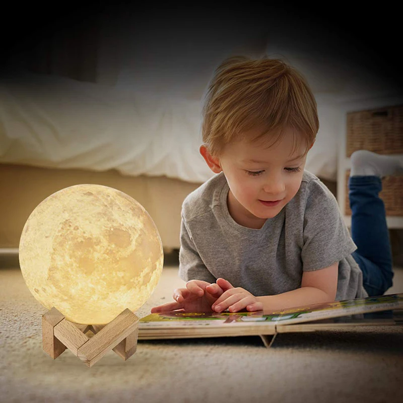
⇡#Stanford Rabbit
After the appearance of the Utah teapot, for a long time, 3D graphics developers had no alternative. Need to test rendering? Of course, a Newell teapot is used. But in the nineties the situation changed slightly. There are new tools for 3D modeling and new models for testing. Stanford University researchers Greg Turk and Marc Levoy joined the case.
Greg Turk
Always Cheerful Mark Levoy
On Easter 1994, Greg walked down University Avenue and stopped by a store that sold decorative items for the home and garden. There he saw a collection of clay rabbits. He really liked the terracotta color of the red clay, and it occurred to Turk that this figurine was ideal for 3D scanning and use in 3D experiments.
“If I knew that this rabbit is so popular, I would buy them all!” — said Greg a few years later. He purchased this rabbit and brought it to the lab, where together with Mark they digitized its shape. The rabbit had only one drawback - there were holes in its geometry.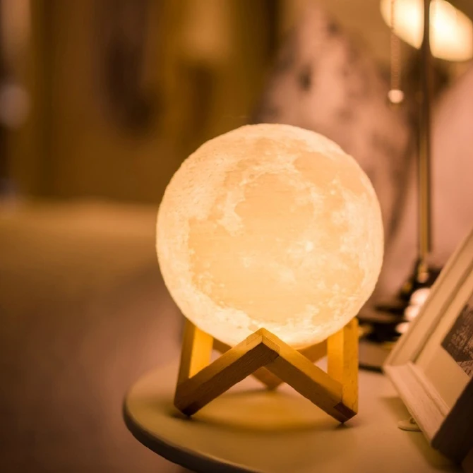 To simplify the polygon mesh, Greg simply patched them up by hand. The model of the Stanford rabbit, which was obtained after the figurine was digitized, contained 69451 triangular surfaces, the original figurine itself was 19 centimeters high.
Since then this model can be downloaded by anyone directly from the site of Stanford University.
In addition to the rabbit, the Stanford repository contains many more models, many of which have also become very popular in the 3D development community. Among the free 3D models available for download, there are, for example, a happy Buddha figurine, a popular Chinese dragon, a beautiful Thai statue, and so on.
⇡#Monkey in Blender
Blender's 3D editor has no analogues. It's the only free professional 3D graphics package that can more or less compete with "whales" like Maya or Lightwave.
Open source, cross-platform and huge modeling capabilities - one can talk about the merits of this program for a very long time.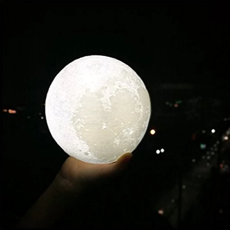 The developers have done everything possible to ensure that this program is in no way inferior to commercial counterparts. And as if in response to Utah's teapot, Blender has integrated its own "non-standard" object - a monkey named Suzanne.
The model of this monkey has a not very complex but non-trivial geometry, which is ideal for test scenes and studying rendering settings. This is a low poly model with 500 surfaces.
The chimpanzee head first appeared in Blender 2.25. It was then, in January-February 2002, that it became clear that the NaN company, which was promoting the then still paid 3D editor Blender, was bankrupt, and therefore would not be able to further develop this project. Its programmers have added a monkey as an Easter egg in the latest release of the program, created by NaN. After that, the Blender license was changed to the GNU GPL, money was raised from creditors, and the 3D editor became free.
Modeled the famous monkey Willem-Paul van Overbruggen, also known as SLiD3.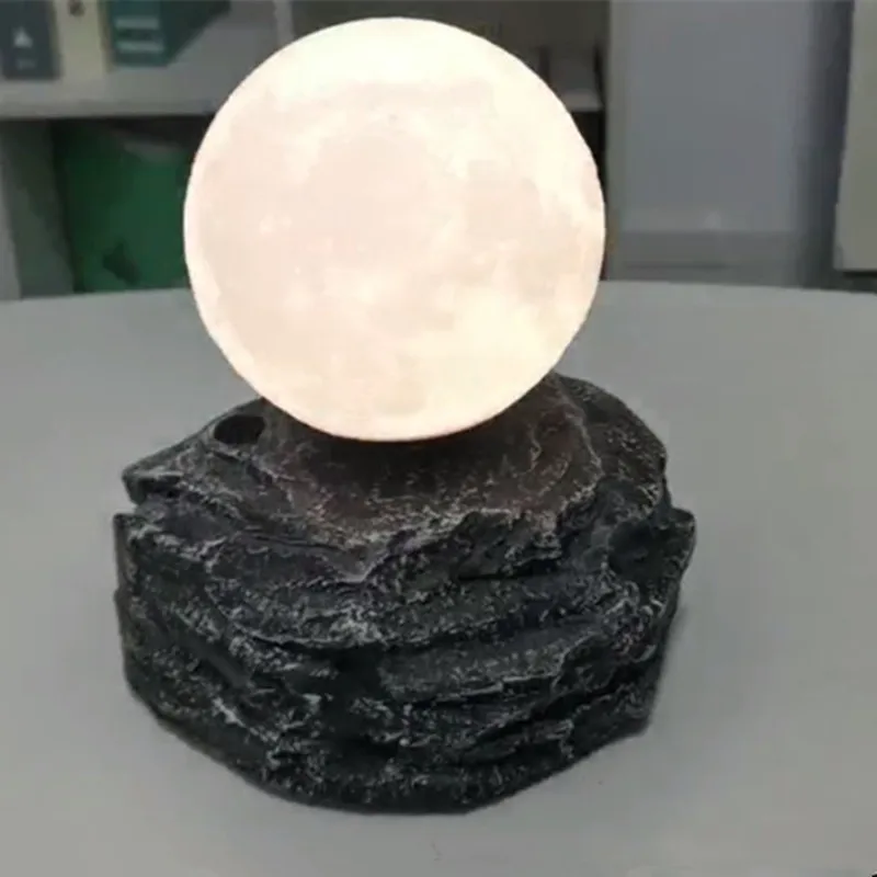 He also gave the name, taking it from Kevin Smith's very specific comedy Jay and The Silent Bob Strike Back. There was an orangutan named Suzanne in this movie.
Suzanne the orangutan and actor Jason Mewes
Suzanne has become a true symbol of the free 3D editor. In 2003, a special competition was even established for artists working in Blender. The annual competition is called the Suzanne Awards, and the winners are awarded a figurine of Suzanne the monkey.
⇡#Cornell box: experimenting with light
One of the most important steps in working on a 3D scene is rendering. And here, I must say, not everything depends on the user. In some cases, even a thorough knowledge of the rendering parameters is not a guarantee of high realism of the image. The quality of the final image is determined by the visualization conditions and, most importantly, by the lighting calculation algorithm.
In the real world, everything is controlled by physical processes. The laws of optics, as well as the properties of materials, determine the picture of the world around us.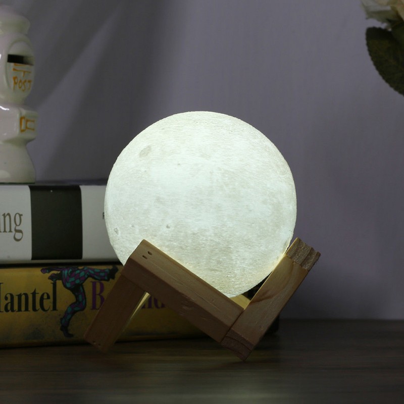 Glass objects are perceived by our eyes as transparent, lemon peel seems to be embossed, and ice frost is matte. The 3D rendering algorithm used for rendering tries to replicate all these phenomena and material properties by simulating physical processes. However, the problem is that this algorithm is not perfect and, as in any school problem in physics, it uses many assumptions and conventions.
For example, the simplest principle for calculating shadows is tracing. It only gives an idea of where the outline of the cast shadow will go. However, in real life, shadows are not always sharp - most often there is multiple reflection of light, when the beam is reflected several times from objects, transferring the color of neighboring objects to other areas and making the shadows “soft”. In 3D graphics, this property is described by global illumination algorithms.
In 1984, a team of scientists in the graphics department at Cornell University was developing new light tracing algorithms. Their work was called "Modeling the Interaction of Light with Diffuse Surfaces". For the layman, this name will not say anything, but a specialist in three-dimensional graphics will accurately guess in this phrase one of the principles for calculating light in a three-dimensional scene - “global illumination”. In the same year, at the popular Siggraph exhibition, Cornell University experts demonstrated the advantage of their system on the example of a simple three-dimensional scene - a hollow cube, inside which the simplest primitives were located.
This cube played the role of a room, an enclosed space, served as a simplified model for simulating realistic light propagation. The model with a box, called the Cornell box, is extremely simple, the light in it makes predictable reflections, and therefore the simple design turned out to be very practical and convenient. So convenient that 3D graphics experts still use it to this day, setting up visualization algorithms and testing new methods for calculating illumination.
The walls of the inside of the Cornell box are painted in different colors. So, the left side is red, the right side is green, the back wall, as well as the "ceiling" and "floor" are white. This is necessary so that the researcher conducting experiments on this model can see the color transfer to neighboring surfaces. You can observe the simplest example of this effect yourself - put something very bright yellow on a clean white sheet of paper, and you will see how the sheet acquires a yellowish tint around the perimeter of this object. If you render using global illumination algorithms, a similar effect will occur in the Cornell box.
⇡#First 3D computer animations
Bell Laboratories has always been one of the largest and most promising teams of scientists. They dealt with the most pressing problems in various fields of science. Over the years of its existence, Bell Laboratories scientists have been awarded the Nobel Prize seven times.
And it is quite natural that the first 3D simulation was performed by the specialists of this center.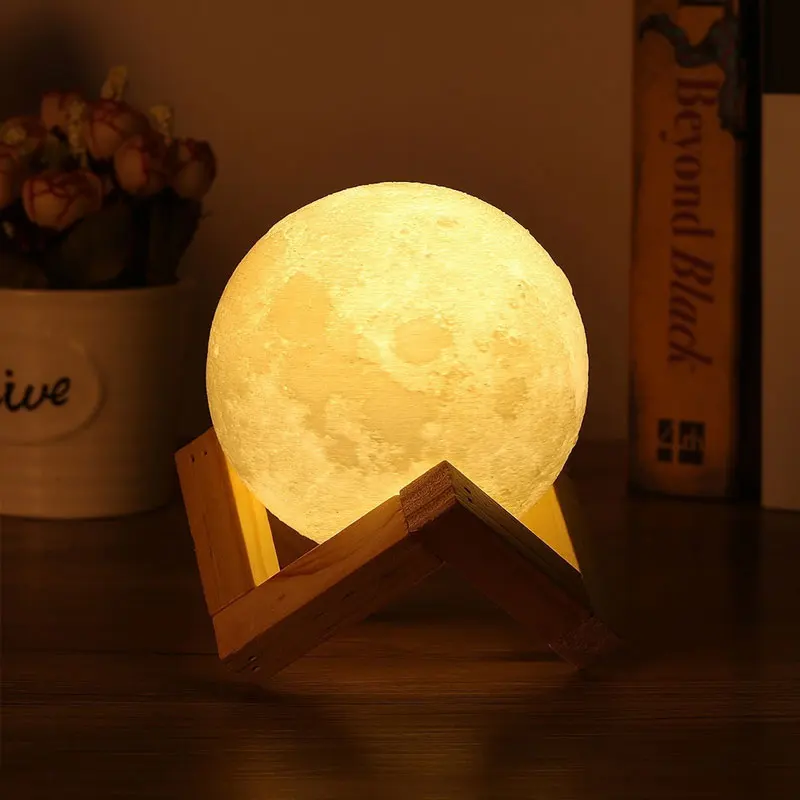 In 1963, a Bell Laboratories employee named Edward E. Zajac demonstrated a program written in Fortran to simulate the movement of a satellite.
Edward Hare, who created the first 3D animation using a computer
He did not set himself the goal of creating the first 3D animation, but it turned out that way.
Fragment of 1963 3D animation
At that time he worked in the department of mathematical research and did mathematical modeling to create mechanisms with a two-gyroscopic stabilization system that could be used in the first communication satellites. Using the ORBIT program (written by another employee of Bell Laboratories), the scientist processed his calculations, receiving a set of punched cards with the results. Using a General Dynamics Electronics Stromberg-Carlson 4020 computer recorder, he printed out the animation microfilm.
Device for printing on film SC-4020
Its plot is simple - two objects are connected to each other by gravity and one object revolves around the second like, say, the Moon around the Earth.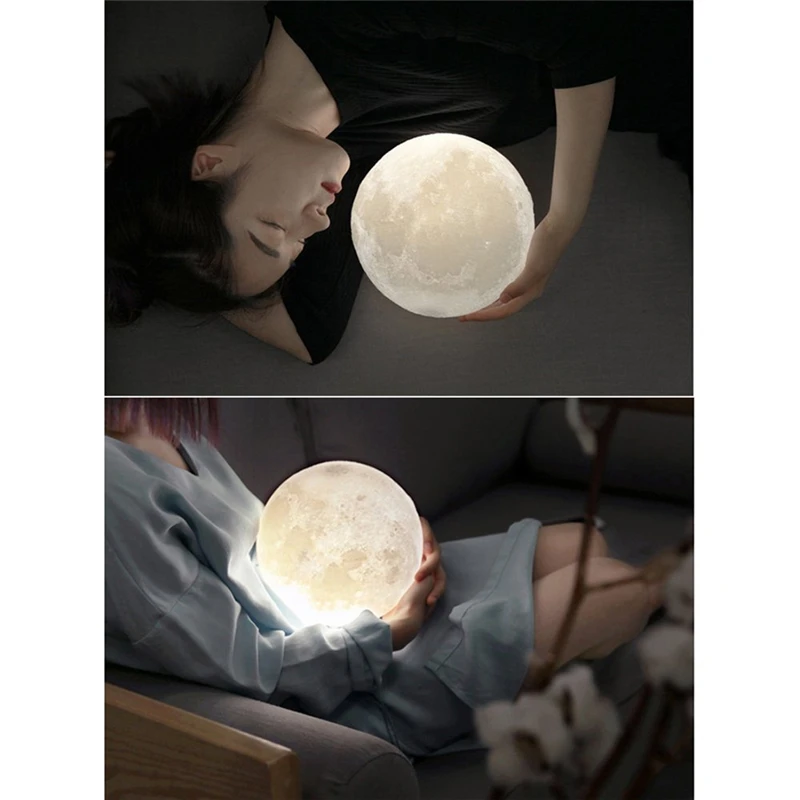 The graphics, as you can see, are minimal, but it's 1963 and it's really the first 3D animation.
Another Bell Laboratories employee who was trying to find a way to make a computer draw 3D animation was A. Michael Noll.
Michael Knoll
Using an IBM 7094 computer in 1965-66, he made several short films, such as "computer ballet", where, with a good imagination, you can see the figures of one-legged dancers moving in three-dimensional space. Most likely, this is ballet on ice. A hinged structure consisting of several nodal points was taken as the "dancers". This option allowed us to simplify the miscalculations.
And so that no one has any doubts that this animation is three-dimensional, Michael Knoll visualized it in stereoscopic mode, drawing the video separately for the right and left eyes. In addition to the "computer ballet", Michael had some more interesting stereoscopic animations with a four-dimensional cube, a four-dimensional sphere, etc.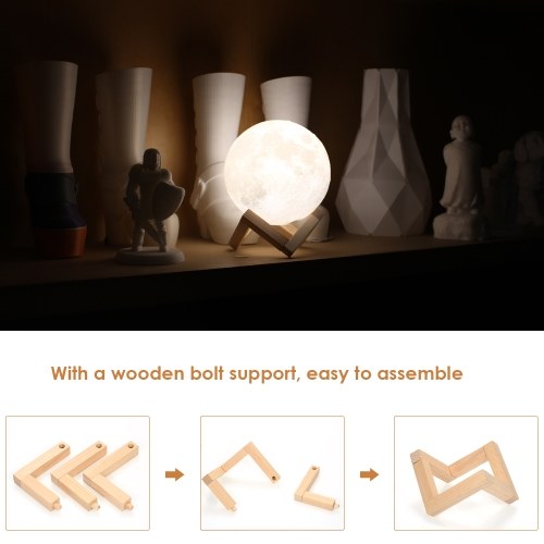 All the images in the animation are "inverted", that is, on the left is the picture for the right eye, and on the right is the picture for the left eye. So, if you want to watch them, focus your vision in front of the monitor screen.
⇡#The first 3D car model: how to scan by hand
The production of many things in the middle of the last century was much slower compared to how it is now. The process of creating a prototype, say, a car, was very long and complicated. But that all changed when Ivan Edward Sutherland set out to develop an interactive interface that would help humans and computers "communicate" with each other.
Ivan Sutherland was once asked how he could come up with and create so many revolutionary ideas in such a short time, from the concept of the interface of all CAD systems to an object-oriented approach to programming. In response, Sutherland only smiled and spread his arms: “But we didn’t know then that it was all so difficult!”
Back in 1963, as part of his dissertation, Ivan Sutherland demonstrated a "robot draftsman" (this is the unofficial name of the project - Robot Draftsman). This program was the first link in the evolution of computer-aided design systems, which today are known as Sketchpad.
Using a computer and a connected light pen, the teller could draw directly on the display screen. The computer determined the coordinates of the touch points of the light pen, and then calculated the geometry of the curve, straight line or geometric figure and almost instantly displayed the result on the screen.
Examples of work done with Sketchpad from the official manual for this system
Simple by today's standards, Sketchpad required fantastic processing power for the time. It ran on a TX-2 computer that occupied several rooms at MIT's Lincoln Research Laboratory.
MIT Lab
In the video below, Sutherland demonstrates the capabilities of the new Human Machine Interface.
His system made it possible to do incredible things for the 1960s - draw lines point by point and create real drawings on the screen.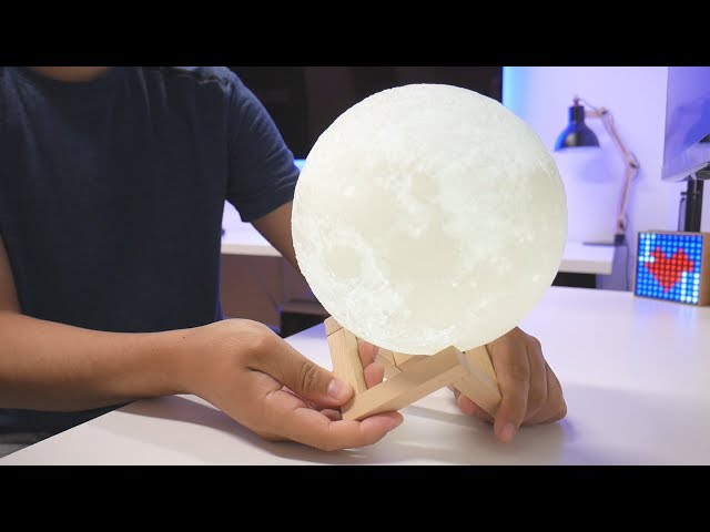 Sketchpad also allowed you to make changes as you work and scale already finished drawing elements.
One of Ivan's most important requirements for Sketchpad was to follow the operator's instructions exactly. It was quite difficult to implement, since the user could “miss” at the right point, and the input device itself was imperfect. To fix this problem, Sketchpad used a system of so-called limiters. These constraints made it possible to manipulate the details of the drawing with absolute precision, for example, to make straight lines parallel or to give two segments the same length. To use these limiters, a whole set of function keys was used, which was located next to the data entry screen.
Diagram of the "light pen" manipulator used with Sketchpad
But in this presentation, the author of the first CAD software already shows a fully working version of the interactive interface with several projection windows and talks very sensibly about the potential possibilities of working with 3D.
Ivan was awarded the most prestigious award in computer science by the Association for Computing Machinery, the Turing Award, for his development of the Sketchpad system.
Modern teachers can learn a lot from Sutherland. This man devoted himself completely to science. But what about himself - he literally did not spare the car for this purpose. Together with his students, Ivan made the first 3D digital scan of a Volkswagen Beetle by hand. Yes, by hand.
The task was very difficult. Then there were no digital scanners or digital photography, so everything had to be done head-on. Students crawled like ants over the car and, using special measuring rulers, drew a polygonal grid on it, what today 3D graphics experts call a wireframe, or a 3D model frame. Before starting work, some details were removed from the car - wheels, bumper, etc., since one base was “digitized” - from all sides, from top to bottom. Was such a sacrifice justified? Of course! Through bullying the "beetle", Sutherland developed a technique for projecting polygonal meshes onto an object, thanks to which modern 3D graphics appeared.
The result of "manual" digitization of the car
Ivan also managed to interest a lot of people with his work, who continued to develop the direction of computer 2D and 3D graphics. And against the backdrop of success, everyone somehow forgot that the Volkswagen Beetle actually belonged to Ivan's wife, and her reaction to her husband's act remained a mystery.
Rendered version of Sutherland's car based on the resulting frame
And who were these "ants" students? There were many outstanding personalities among them. One of those who made the model car was named John Edward Warnock. Ten years after this story, he will become a co-founder of the well-known company Adobe.
Another young graduate is Alan Curtis Kay, the one who invented the modern tablet PC concept called the DynaBook (see Small Stories of Big Design: From Electric Shavers to Tablets).
Junior Researcher B˘i T˝ờng Phong also contributed to this model. Phong's model is used in many 3D engines today.
It was on the model of the first 3D car that Phong tested his famous shading system, which later received his name - Phong. In any 3D editor that has the ability to customize materials, among other options, you can select the Phong shading algorithm. The Phong method is based on the interpolation of surface normals by rasterized polygons and allows you to calculate the color of pixels, taking into account the interpolated normal and the light reflection model.
The Sutherland project was virtually unparalleled. The only system that had a similar principle was the commercial development of General Motors and IBM, which was called DAC-1 (Design Augmented by Computers). This console was also controlled by a light pen, but was less convenient and also expensive.
⇡#Left alone: the first computer animation of a hand
The habit of chasing the power of computer hardware has led to a widespread belief among users that it is impossible to get a 3D image without a modern video card.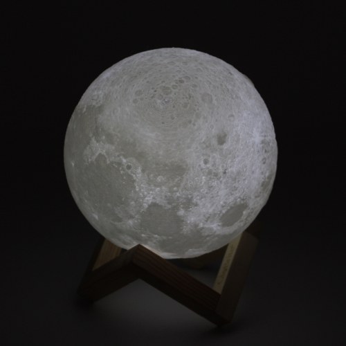 But that's not the case at all. Imagine that the third dimension was threatened more than half a century ago. Even before the moment when the computer truly became personal, engineers could (and did) 3D animation. And the future founder and president of Pixar, as well as the head of Walt Disney Animation Studios and DisneyToon Studios, Edwin Catmull, had a hand in this.
And he did it in the literal sense of the word - he digitized his left hand and created a demonstration animation of finger movements on it.
Catmull has been interested in the animation process since childhood. He even had his own makeshift stand, where Edwin tried to make the first primitive cartoons. However, like many other university graduates, he did not immediately find his calling. Immediately after graduating from the University of Utah, he first went to work for Boeing, but a year later the economic crisis forced Boeing to lay off thousands of employees, and Ed was among them. After that, the recent graduate returned to the university again to continue his postgraduate studies.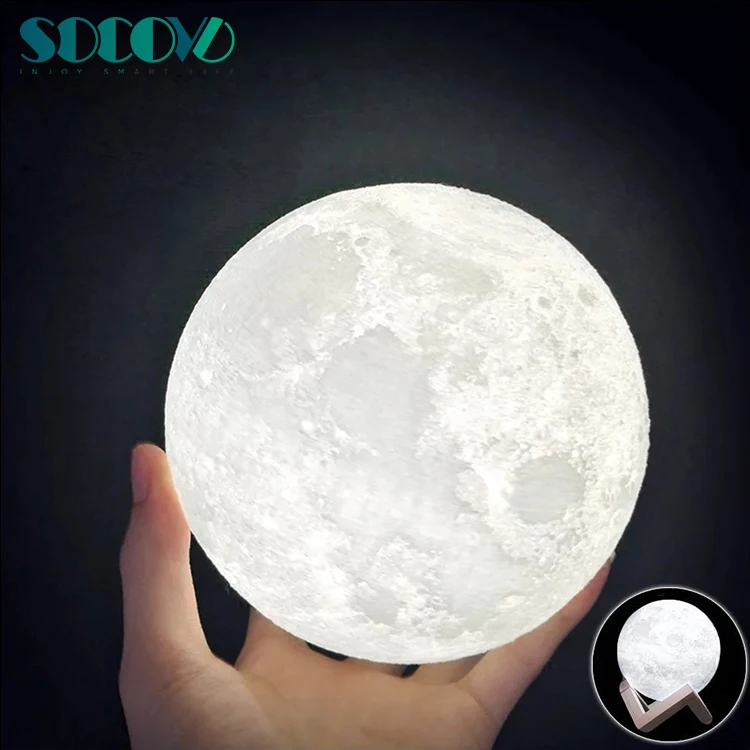
Ivan Edward Sutherland, then a professor at the University of Utah, became Catmull's mentor and encouraged the young graduate student to study interactive computer graphics. Catmull used the same method as Ivan to digitize his car. The animation of the 3D hand was created in several stages. Compared to Ivan's large-scale Volkswagen Beetle digitization project, Catmull found it a little easier - he simply painted a cast of his left hand, marking the location of the edges and nodes of the polygonal grid on it. Then, in the laboratory, this grid was read by a special device, and a three-dimensional model was compiled based on the data obtained.
Catmull's hand digitization process
Catmull wrote a program to animate this model. This animation was rendered and used as a nice addition to the graduation project. The surface of the hand was deformed, the fingers were bent and unbent, and the hand itself was turning on the screen. For greater effect, Catmull even allowed to "look" inside the model, demonstrating to the viewer that the 3D arm is hollow inside.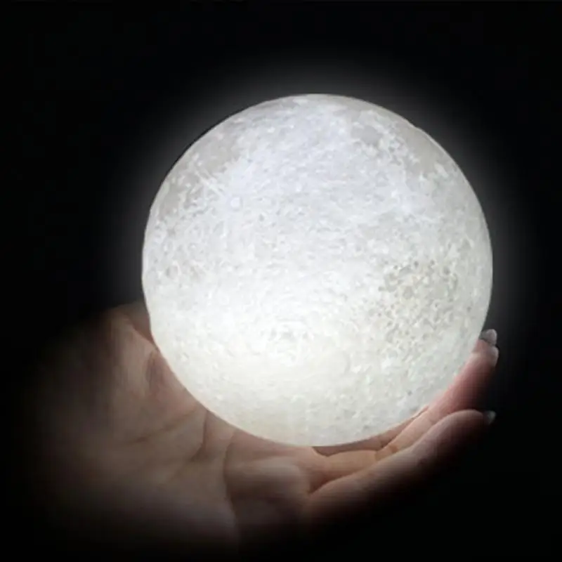
The work of young scientists was not in vain. A model of a hand rotating in 3D was used in the sci-fi movie Futureworld 1976 years old. He was talking about a resort hotel with robotic staff. To imitate high technologies, everything was used - both rendered animation and the wireframe of a three-dimensional model.
In addition to this three-dimensional hand, the students made an even more complex work - an animated model of a human head.
It was prepared by Catmull's friend and colleague Fred Parke, who also took part in digitizing the model of Edward's left hand.
Fred Park
He even tried to synchronize the sound and lip movement of the computer model. And this is in 1974!
Students called the human model Baldi, that is, "bald". Its frame consisted of 900 triangles.
In the mid-eighties, the laboratory of Dominic Massaro continued to work on this model and, using a more advanced technique, “revived” the head, endowing it with a large set of speech facial expressions. Professor Massaro himself slightly changed the name to the Italian style - Baldi and registered it as a trademark. And not so long ago, under his leadership, the release of an application for iOS was launched, in which there is a talking 3D head, made back in the seventies.
⇡#Cat and equations: Soviet computer animation
The term "computer animation" in the middle of the last century was something very exotic. Computers, as well as printing devices, were only at the disposal of research organizations and, of course, the military. Well, in the Soviet Union, people did not hear about computer animation at all, with the exception of a small group of enthusiasts who assumed that it was quite possible to “draw” animation with the help of computer technology.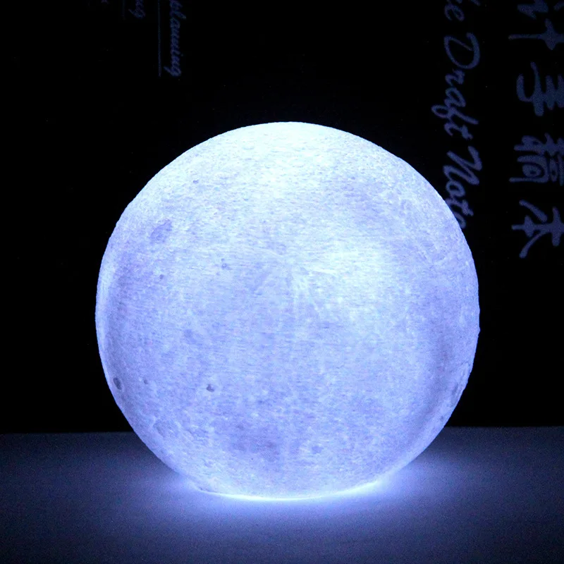 One of these people is the mathematician Nikolai Nikolaevich Konstantinov.
This man is a real legend in Russian mathematics. Konstantinov is one of the most talented and extraordinary scientists who managed not only to make a huge contribution to the national science and education system, but also to pass on his knowledge to future generations. Among his students there are a lot of prominent mathematicians and scientists, not to mention the winners of mathematical competitions and olympiads.
Back in 1968, he created the first computer animation for a minute and a half. The object of his attention was a cat, hence the name of the mini-cartoon - "Kitty".
The mathematician decided to create a cartoon by programming the movements of a cat and printing each animation frame with a redrawn silhouette. The realization of such an idea could only arise from a person who not only has an excellent understanding of higher mathematics, but also sees its practical application.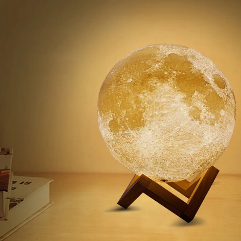
Since the animal's muscles, by contracting, control the acceleration of certain parts of the body, Konstantinov decided that second-order differential equations could well become the basis of the animal's movement algorithm. The graphical interpretation of the cat's silhouette was achieved using a character array. The mathematician broke the outline of a cat into parametric “bars”, and then, using hypothetical formulas describing the animal’s gait, recreated a simple scenario of movements that included several steps, turning the head and slowing down.
In this work he was assisted by two students of Moscow State University - Vladimir Ponomarenko and Victor Minakhin. Nikolai Nikolaevich later recalled a funny detail of this project: in order to derive the correct formula for the movements of a cat, Viktor tried to portray a cat - he got on all fours and walked on the floor, trying to understand which muscles were involved in the work.
Although Konstantinov himself subsequently refuted the realism of the achieved result, referring to the hypothetical nature of mathematical calculations, it is hard not to notice how realistically the animal moves in the frame.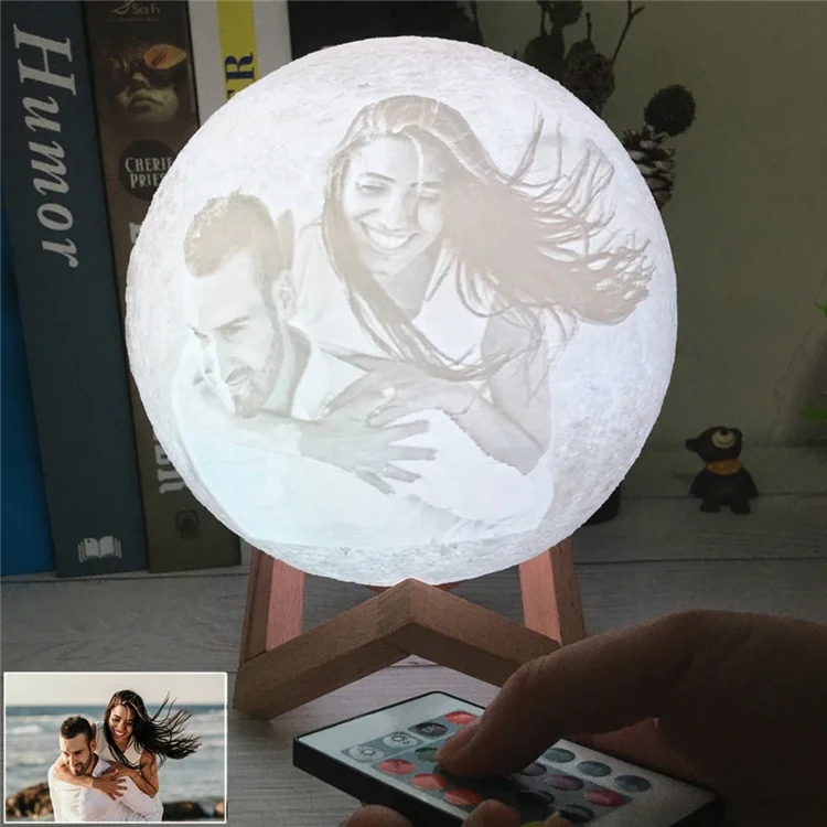
At the Department of General Control Problems of the Faculty of Mechanics and Mathematics of Moscow University, the theoretical part of this problem was prepared, and the debugging of the program itself for calculating differential equations and its operation was carried out at the Computing Center of the Moscow State Pedagogical Institute. The computer that was used to calculate this animation was proudly called BESM-4 (“Large Electronic Computing Machine”).
BESM-4 had very little in common with what we call a computer today. Only 30 such devices were produced throughout the country. RAM in BESM-4 was made on ferrite cores (8192 words, 45-bit words, organized into two cubes of 4k words). The performance of this "cabinet" was up to forty thousand operations per second. The printer for a large electronic calculating machine had a no less capacious name - the alphanumeric printer ATsPU-128.
If you look closely at the frame-by-frame rendering, you can see minor random unwanted artifacts - in their own way these are the first "glitches" of computer visualization, that is, rendering.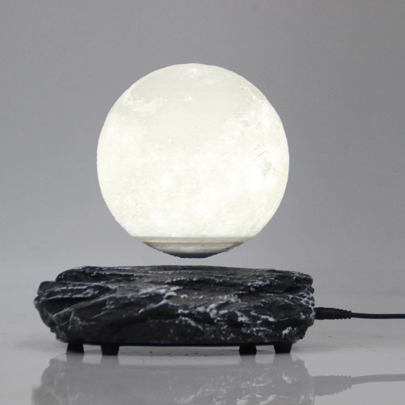
Separate frames of animation "Kitty"
As for the cat's face at the beginning of the short film, this is not the work of a mathematician, but of a merry artist who also did animation for the unforgettable Soviet film "Merry Fellows". He was also invited to work on this project.
Interestingly, at that time Konstantinov was not the only person in the USSR who used the method of computer animation. However, other attempts at visualization on a computer, such as, for example, animation of processes inside a DNA molecule, were boring and incomprehensible to an unprepared viewer.
⇡#Conclusion
Now the computer is a universal tool. It can be used for drawing, and for creating animation, and for preparing videos. The only thing he lacks is creativity. However, perhaps this is a matter of time.
The advent of computer technology and the development of computer graphics in a sense allowed a person to take a fresh look at the world. Much of what was previously inaccessible to human vision, what was too fast or too slow, very small or too large, became obvious and understandable in a computer model.