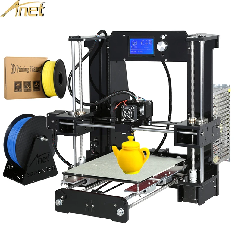
3D printing led
Light up your 3D prints with LEDs and bulbs!
Robots, automatic pet feeders, movie props, drones – the list of cool projects that combine the power of 3D printing and electronics is endless. That said, some if not most of the projects can be pretty intimidating. And you can get discouraged easily when you realize, that you need to learn how to solder, write your own code for Arduino or even design a circuit board. Fear not, because this time you won’t need any of that and yet we’ll light up our 3D prints!
Generally speaking, you have three options when it comes to simple light sources that work well with 3D prints:
- LED strips
- LED lightbulbs
- Small diodes
Old-school bulbs are not suitable since they generate a lot of heat.
LED strips
One of the easiest ways to add lights to your 3D prints are LED strips. They’re cheap, often come with a remote, they’re available both white and RGB and most importantly, they are easy to power. You could buy a whole roll of RGB LED strip and use your own LED controller and power supply, but not this time – we said no soldering! So instead we suggest buying an LED strip with a USB connector. This way, you can power it with any old phone charger, your PC, or a power bank.
The obvious downside of USB is its limited power, so you can’t get really long or extremely powerful LEDs. But really powerful LEDs can get pretty hot, so we wouldn’t want to use them anyway, especially with PLA.
LED strips always come with a double sided tape applied to their bottom side, so it’s really easy to install them. If you stick them on the inside wall of a box you can get nice and even illumination. Then print a front plate with a text or a logo and you’ll end up with a similar result as our recording sign.
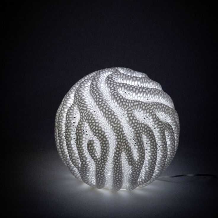
Alternatively, you can print and wrap a cylinder with the LEDs and this way you’ll have the light coming from the center of the object.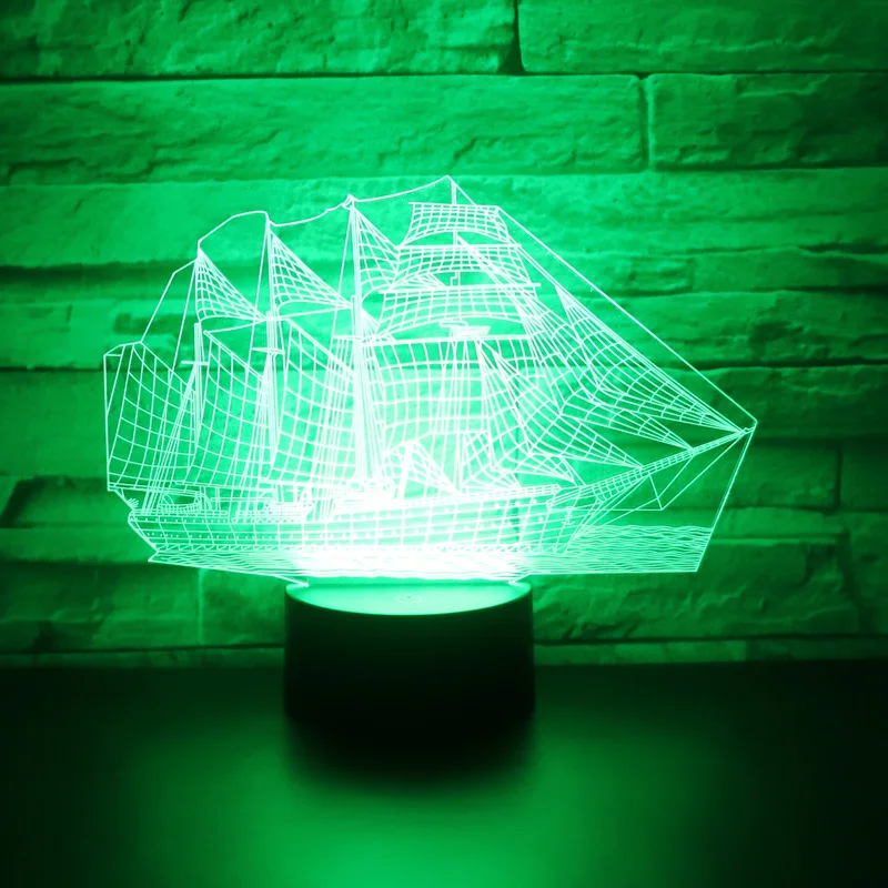 Consider printing a diffusor from, for example, clear PETG. That will make the illumination more even and hide the individual LED chips, as seen on this Voronoi/triangles lamp.
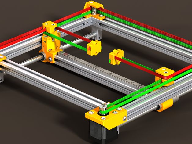
Also, LED strips work great as a light source for the build plate. You just have to print a simple light bar holder and attach it to the top of the frame.
Here are some USB LED strip listings, but you can most likely get them in your local electronics store as well:
- Aliexpress
- US Amazon
- UK Amazon
Waterproof or non-waterproof strip led strips?
Whenever you can, go with the non-waterproof version. The GEL coating that manufacturers use to waterproof the LED strip adds weight, makes the strip much harder to bend or shape. Last but not least – without direct contact with air, the LED chips will run hotter. The gel coating is pretty much unnecessary for our use.
Cutting LED strips
A cool thing about LED strips is that you can cut them with regular scissors to adjust the desired length. The spots, where you can cut, are always clearly marked, so make sure to watch out for them.
LED Lightbulbs
Using lightbulbs with 3D prints is pretty straightforward, you just have to buy a lightbulb socket with a cord and attach it to your 3D print. We really like the IKEA SEKOND cord set. It has a nice textile sleeve for the cable and comes in a variety of colors.
There are a few commonly used sizes of sockets:
- Medium or Standard: E27 (diameter of 27 mm)
- E27 is usually interchangeable with E26
- Intermediate: E17 (diameter of 17 mm)
- European: E14 (diameter of 14 mm)
- Candelabra: E12 (diameter of 12 mm)
Oldschool light bulbs were terribly inefficient and used to produce a ton of heat, which would be a problem with our printed parts. Luckily for us, LED light bulbs are mainstream these days, and the amount of heat they produce is significantly lower. Still, be mindful of this and check how hot does your light bulb get.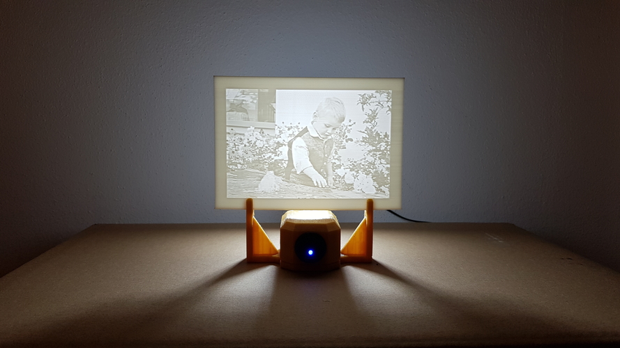
It’s quite likely, you’re not going to 3D print all of your lamp shades, maybe just a few as a cool design piece. In that case, modern smart bulbs are a great way to make your creation even cooler! They can be controlled with a voice assistant (Google Home, Alexa, Apple Homepod) and change color on demand.
Here are some smart light bulb options:
- Xiaomi Yeelight – significantly cheaper than the competition, yet fully featured
- Phillips Hue – expensive, but lots of fancy accessories
- LIFX – expensive, but greater maximum brightness
Whichever lightbulb or cord set you choose, there is one challenge in front of you. And that’s hooking up the power. Mains electricity voltage, which light bulbs run on, varies between 120V to 230V. Either of which is high enough to seriously burn you or even kill you.
So if you don’t know what you’re doing, please just stop right here and consider asking someone with more experience for help.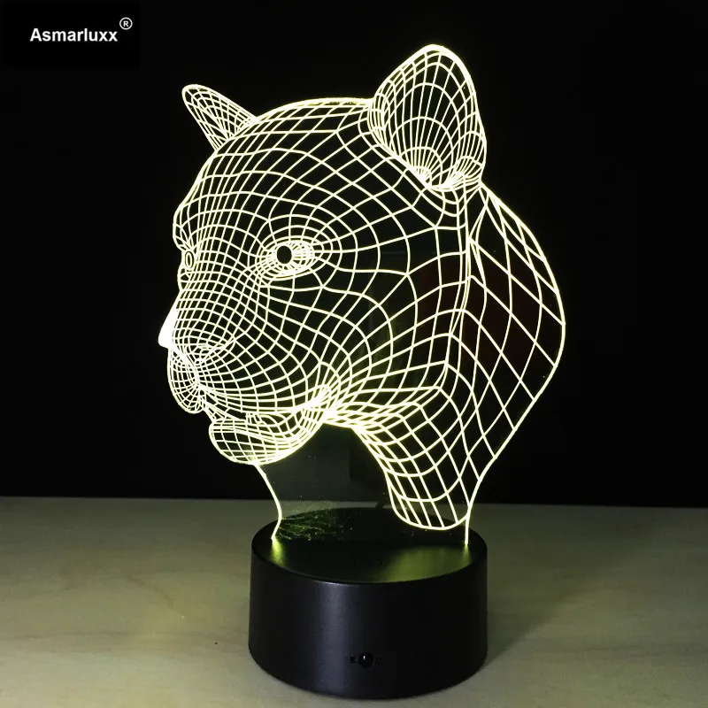 But if you know what you’re doing it’s as simple as switching the circuit breaker off, triple checking that it actually is off, connecting the phase (brown/black) and neutral cable (blue), insulating the connection and turning the power back on. Most cord sets even come with a quick release mechanism for the cable connection.
Model links
- “Recording – quiet please” backlit sign
- Voronoi/triangles lamp
- Zuzanna lamp on Cults3D
- Ribbon lamp on Cults3D
- Prusa LED lightbar
- LED bridge lamp
- Halloween Crow on Thingiverse
Small diodes
The two previous solutions were for rather big prints. In contrast to that, individual diodes can be really tiny and fit almost everywhere. They’re usually powered by 3.3V, which is (un)coincidentally the voltage of most button cells, a type of small batteries.
For under $10 you can get a set of hundreds of LED diodes in various colors, which will usually last you, well, forever.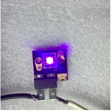
LED diodes on:
- Amazon US
- Amazon UK
- Aliexpress (just $0.80 per 100)
And to attach the battery to the diode, you can either use a rubber band or a printed part.
We’ve used this technique in our Halloween crow and in our miniature tabletop gaming article.
Conclusion
We’ve just scratched the surface with using electronics in 3D prints. But it’s often easy to overcomplicate things, even when it’s not necessary at all. Add even a small light to your 3D print and the result will go from good to awesome! Now we want to see what you’ll come up with! Post your creations on Twitter with the handle @Prusa3d, on Instagram with the hashtag #prusa or in any of our fan facebook groups. Happy printing!
3D Printing Quantum Dot LEDs
Home Articles 3D Printing Quantum Dot LEDs
Developing the capability to 3D print various materials could enable the freeform generation of active electronics in unique functional, interwoven architectures.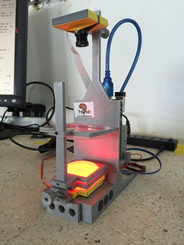 Achieving such a seamless integration of a diversity of materials with 3D printing is a significant challenge that requires overcoming discrepancies in material properties in addition to ensuring that all the materials are compatible with the process. 3D printing Quantum Dot LEDs: a myth or reality?
To date, 3D printing was limited to the use of specific plastics, passive conductors, and some biological materials. Princeton University, however, have gone far beyond two-toned action figures with a research conducted back in 2014: they tried to fully 3D print world’s first LED light sources. To make the LEDs (Light-Emitting Diodes) from scratch, the researchers build a custom 3D printer for their research purposes. They finally managed to mix and match five different materials into the first fully 3D printed LED light sources.
3D printer for Quantum Dot LEDs – engineered by Princeton University. It took almost two years to develop the system. Picture by Kong et al, Nano Letters.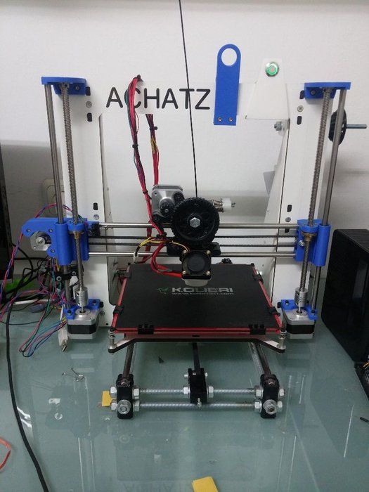
3D Printing Quantum Dot LEDs
The LEDs that the Princeton University team created are so called ‘Quantum Dot LEDs’. They are a lot like the LEDs that are built into cellphones and television screens, but less stronger in output today. The expectation is that printed Quantum Dot LEDs could be more energy efficient in the end.
3D Printing Quantum Dot LEDs: diverse material classes can be 3D printed and seamlessly integrated into device components with active properties. The illustration depicts the layers of the LED device. Picture by Kong et al, Nano Letters.In the above picture, the seamless interweaving of five different materials is demonstrated. The build includes including emissive semiconducting inorganic nanoparticles, a kind of elastomeric matrix, organic polymers that are used as charge transport layers, solid and liquid metal leads, and finally an UV-adhesive transparent substrate.
More specifically, layer 1, on the bottom, has a metal ring made of silver nanoparticles acting as a metal contact to the electrical circuit.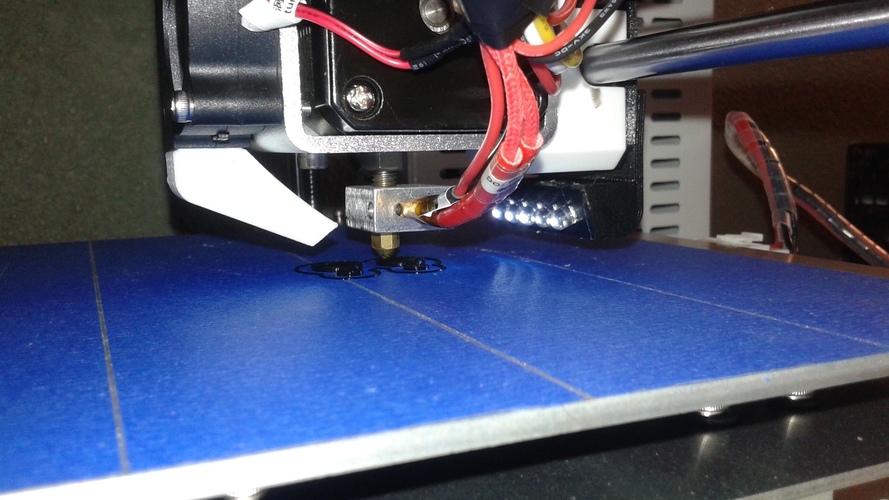 On top of that are two polymer layers (layer 2+3) which together supply and shuttle electrical current to the next layer (layer 4), that contains the quantum dots. The quantum dots are made of cadmium selenide nanoparticles wrapped in a zinc sulfide shell. As the electrons bump into these quantum dots, they emit orange or green light. The light is topped off with a cathode layer (#5) made of eutectic gallium indium, through which the electrons flow out of the diode and emit the light.
In addition to combining metals and polymers, some of the materials were hydrophilic (water-loving) while others were hydrophobic (water-repelling). Some of them were liquid materials while others were solids. The Princeton University researchers says it’s the largest number of distinct material classes that have been 3D printed into one object.
Proof-of-Concept: 3D printed Quantum Dot based LEDs
As a proof of concept for demonstrating the integrated functionality of the various materials, quantum dot-based light-emitting diodes (aka QD-LEDs) were 3D printed. The properties of these quantum dots are that they emission pure and tunable colors. By further incorporating the 3D scanning of surface topologies, the ability to print devices onto curved surfaces was demonstrated.
Finally, it was shown that novel architectures, not easy to access using standard microfabrication technologies can be constructed by 3D printing a cube of encapsulated LEDs. In the cube, every component including the electronics were 3D printed. Overall, these results suggest that 3D printing is more versatile than has been demonstrated to date and is capable of integrating many distinct classes of uncommon 3D printing materials.
3D Printed LEDs Performance
3D printed QD-LEDs: functional or decorative?
The printed LEDs didn’t come close to beating the really functional LEDs as used in functional lighting applications out there. However, the Princeton Uni team expects that by controlling the thickness and uniformity of the quantum dots, and by experimenting with different ink formulations, the performance of the 3D printed LEDs could get better in the future. We’re curious to see what comes up next!
You can find out more about the study of the Princeton University in the online ‘Nano Letters’ Journal.
3D printer taught to print photodetectors and LEDs on flexible substrates
3D printing
Complexity 3.3
University of Minnesota, McAlpine Group
American researchers have learned how to 3D print polymer photodetectors on flexible and curved substrates. The scientists demonstrated the technology using photodetector arrays on flexible and hemispherical substrates, and showed that the same method can be used to print LEDs. Article published in Advanced Materials .
Engineers and scientists have long proposed the use of 3D printing not only for the production of frames and device cases, but also for printing electronic components. There are quite a lot of developments in this area, but so far 3D printing of electronics has not been applied in practice due to a number of unsolved problems. For example, it is difficult to print complex, multi-material, multi-layer devices in this way, while it is not possible to print on flexible substrates for medical and wearable devices.
Michael McAlpine and his colleagues at the University of Minnesota have created a 3D printing method for semiconductor electronic devices that allows them to be printed on a variety of substrates, including flexible and curved ones. The researchers had to choose printing materials in such a way that they would not only allow the creation of functional devices, but also be sufficiently viscous when printing on inclined surfaces.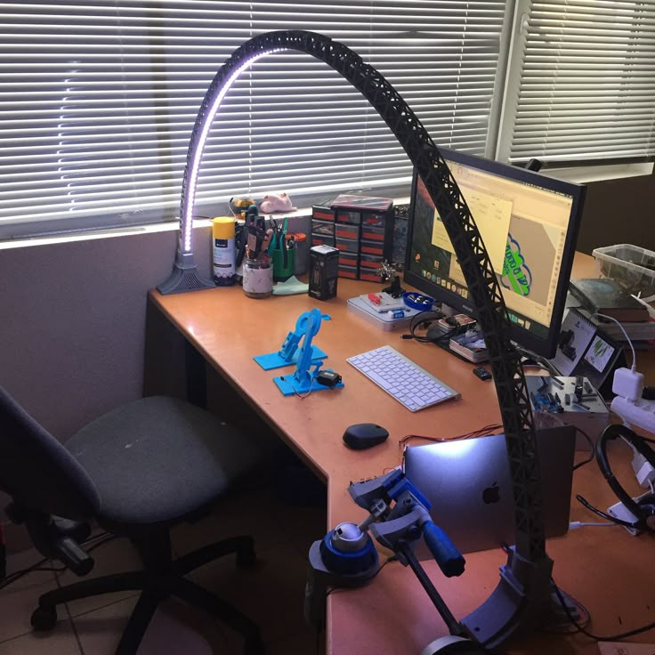
In their study, the scientists focused on printing photodetectors. At the first stage, a thin polymer film is applied to the substrate. Then, conductive tracks of silver nanoparticles are printed on it, connecting individual photodetectors and forming the basis for them. The printer then prints a transparent anode made of the conductive PEDOT:PSS polymer at certain locations on the tracks. On the anode, the printer prints a layer of photoactive polymer, which is then coated with an insulating layer of silicone polymer and a gallium-indium liquid alloy cathode.
Layout of layers in photodetector
Sung Hyun Park et al. / Advanced Materials, 2018
Share
When photons hit the active layer of the photodetector, the charge carriers in it separate and move to the cathode and anode. Tests of photodetectors have shown that their external quantum efficiency, which reflects the ratio of the charge carriers that have arisen to the number of photons that hit the detector, reaches 25.3 percent.
Researchers have created prototypes of several types, including an array of photodetectors on a flexible substrate, as well as a hemispherical substrate. They demonstrated the operation of prototypes and showed that they can be used as matrices for image reading:
Prototype photodetector array and its operation as a photoarray
Sung Hyun Park et al. / Advanced Materials, 2018
Share
In addition, the authors showed that the active layer material can be changed from photosensitive to photoemissive and thus create an LED. The authors of the study believe that in the future the technology can be improved and used to create prosthetic eyes.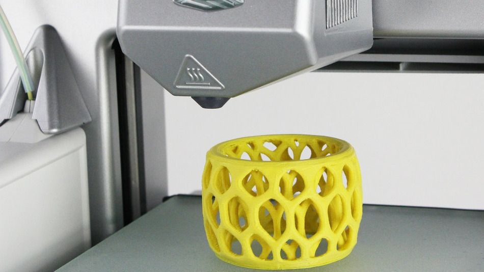
At the beginning of the year, Michael McAlpine's group created a 3D printer capable of printing on a moving surface by tracking its movements. As an example, they showed the process of printing a working LED circuit on a person’s hand, which receives energy from an external current coil.
Grigory Kopiev
Hi all!
First, a 'small' lyrical digression.
Approximately a year and a half ago, I caught fire with the HPL Fireball project to upgrade cheap Chinese LED PTFs to an acceptable level in terms of luminous flux intensity. The optics in these PTFs are at a decent level, but they saved money on components. As part of this project, the board and LEDs were replaced with more efficient ones, but of the same size - there are a lot of photos on the network with the results of the upgrade (including STG)
General view of the LED PTF can be seen in the photo (not mine, stolen on the Internet)
The problem in my case was that on my car the PTF reflector has the shape of a parallelogram rather than a circle. But at the same time, the useful area of \u200b\u200bthe reflector of the original LED PTFs approximately coincided with the area of mine. Those. I thought that in principle it is possible to grow them somehow.
I lived with these thoughts for a while, but then I decided it was time to act - I bought another set of regular PTFs, a set of LEDs, a handful of Cree XP-L LEDs, a piece of aluminum foil, a couple of 2.1 A drivers and started splicing it all .
The body of regular PTF is made of plastic, LED - of cast aluminum. I cut off everything superfluous, tried to combine the optical centers and spliced them together using cold welding. I also covered it with polyurethane sealant on top for protection (I thought that the weakest link in this design was she, naive). In general, there was not enough electrical tape for a complete set.
Monthly operation experience has shown that LEDs do not live very comfortably in this configuration (for a number of reasons, I learned about them after opening) - they began to bake / degrade (the temperature of the foil to which they were soldered was a little more than 100 degrees after 40 minutes of work), and it became clear that everything needed to be completely redone.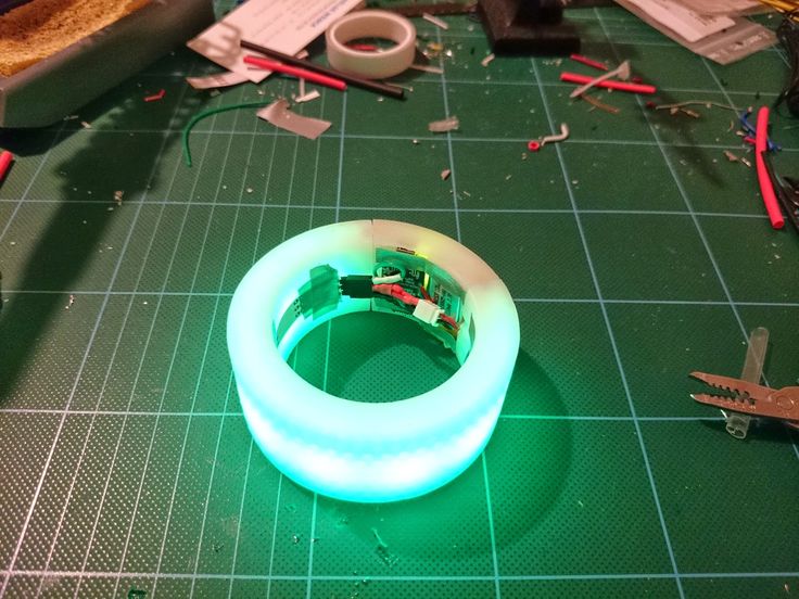
This time I decided to approach the matter more thoroughly - to abandon the rigid collective farm (read cold welding) and provide the most comfortable life for LEDs. He designed composite radiators - part of copper, part of aluminum. The LEDs will be soldered directly to copper radiators (special platforms have been prepared for this) - in general, the sinkpad is resting. This will ensure the fastest cooling of the crystals of the LEDs themselves and faster heat distribution over the radiator, i.e. bottlenecks in the form of a dielectric layer with a low thermal conductivity (compared to copper) and a layer of thermal paste between a not very even aluminum substrate and a heatsink have been eliminated.
But at the same time, there is such a moment - you need to somehow fix the entire optical system (the LEDs themselves, the reflector and the lens) on the radiator. During the design of the radiator, only one of the reflectors was turned in the hands (there are only 2 of them, 1 for each PTF), it just had 2 technological 'legs' into which the screws were screwed.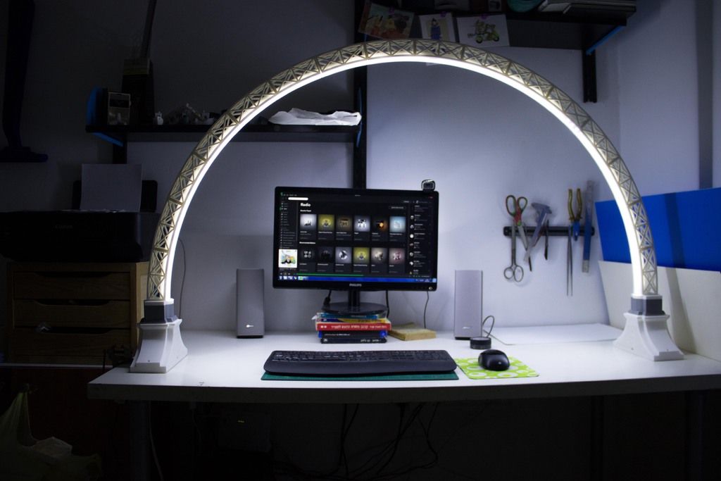
I decided to 'get involved' with them. Therefore, in addition to radiators, bushings were also made, which set the gap between the reflector / lens and the LED.
The result is the following model:
for its design, a whole bunch of different measurements were made, the specification for all kinds of connectors (including h37) was studied to repeat all the connector keys in the metal so that the horizons would match (now I understand that this was also my mistake, I had to print the keys on printer). Since I don't have my own printer yet, I had to look for it. And then my favorite university came to the rescue (it's nice that you are remembered even a few years after graduation) - the layout was printed out (more precisely - not one - there were several errors) quickly enough, for which many thanks to my beloved teachers.
The production of radiators was ordered in China (it turned out to be almost half cheaper than the production in Russia). Already when the parts were on hand, I discovered that on the second reflector a year ago I personally sawed off the very legs of the reflector on which it was supposed to be attached, which put a pig on myself.
The Chinese did the same - the holes in the platform for the bushings were 0.2 mm smaller than their diameter, which, of course, did not want them to stand in their place. An attempt to use the reamer was unsuccessful - he lost the plane with which the end of the sleeve contacts.
The general view of the assembly turned out like this:
It became clear that one cannot do without another 3D printing of the 'adapter'. Reworked the adapter model for the reflector several times. Initially, I also assumed the manufacture of a 'mask' for this entire system from sheet plastic (a plastic folder) by cutting it on a plotter. It was needed only in order to cover all the intestines of the resulting structure. Ultimately, this mask turned out to be a functional element that both covers obscenities and fixes the reflector with respect to light sources on the radiator platform.
At the university, for technical reasons, this time there was no help for me, I had to use the announcement section on the site. From there, I learned that, it turns out, we have a manufacturer of 3D printers in our city. The guys from Cronos kindly agreed to help me in my 'trouble'.
Printing of parts was somewhat complicated by the fact that the estimated temperature of the radiator will be about 80 degrees, which is already at the border of the temperature range of ABS plastic operation. In addition, it will require a one-time warm-up up to 90-100 degrees (the transparent part of the PTF is glued to the body with butyl rubber sealant, at this temperature it softens and the entire sandwich can be glued back together) for 15-20 minutes. In order not to have problems with plastic during operation, we decided to print with Eternal plastic from REC (a little more shatter-resistant compared to ABS).
Details printed perfectly - if it were not for the color of the plastic and my curvature and inexperience - just take it and use it (otherwise - you still have to cut some details on the plotter to cover the curved cuts of the reflector and front mask and you will have to use aluminum tape on the sides to add a little regular 'brilliance').
My inexperience in modeling for 3D printing had a little effect on the final product - I fit the nuts into a circle with a diameter of 6 mm (nuts M3), and in the end I got a circle with a diameter of 5.5 mm, which is why the nuts are not eager to sit down in their places. All the same, it was necessary to lay a small gap. The load at the attachment points is minimal, the self-tapping screws do an excellent job with this task (initially, it was on them that the reflector was supposed to be fastened through the bushings).
Most of all I was worried about the thin wall along the edges of the part at the very top of the 'ladder' - the thickness is only 1 mm, the length of the arc is almost 4 cm, the height is 3 mm.