3D print surface problems
Poor Surface Above Supports
Poor Surface Above Supports
One of the major benefits of Simplify3D is the ability to create innovative support structures which allow you to create incredibly complex parts that would be hard to manufacture otherwise. For example, if you have a steep overhang or part of your model with nothing below it, then a support structure can provide a foundation for these layers. The support structures created by Simplify3D are disposable and can be easily separated from the final part. However, depending on your settings, you may find that some adjustments are needed to perfect the surface quality on the underside of your parts, right above the support structure foundation. We will explain the key settings below and how they can affect your prints.
Common Solutions
Lower Your Layer Height
The overhang performance of your printer can be greatly improved by lowering your layer height. For example, if you reduced your layer height from 0. 2mm to 0.1mm, your printer will create twice as many layers, which allows your printer to take smaller steps when creating an overhang. For this reason, your may find that you need support structures for any overhang above 45 degrees when using a 0.2mm layer height, but your overhang performance may improve to 60 degrees if you lower your layer height to 0.1mm. This has the obvious advantage of decreasing your print time and reducing the amount of support structures required for the print, but it will also allow you to create a smoother surface on the underside of your parts. If you find that you need to increase the print quality in this area, this is one of the first settings you will want to adjust.
Support Infill Percentage
Just like the interior of your part, you can also adjust the density of your support structures by changing the Support Infill Percentage. It is common to use a value around 20-40%, but you may find that you need to increase this value if the bottom layers of your part are drooping too much. Many users also prefer to use Dense Support Structures for this task, as they allow you to use a lower density for the majority of your supports, and only use a higher infill percentage near the very top of the support structures.
Vertical Separation Layers
Creating removable support structures involves a fine balance between the amount of support provided to the model, and how easy the supports are to remove. If you provide too much support to the model, the support structures may start to bond to the part, making them difficult to separate. If you provide very little support, the disposable support structures will be easy to remove, but the part may not have enough of a foundation to print successfully. Simplify3D allows your to customize the separation settings, so that you can choose the correct balance between these different factors. The first setting you will want to check is the Upper Vertical Separation Layers. This setting determines how many empty layers are left between the support structures and the part. For example, if you are printing your support structures with the same material as your part, it is common to use at least 1-2 vertical separation layers. Otherwise, if you used 0 separation layers and you are printing everything with the same material, the supports may bond to the part and can become difficult to remove. So this is one of the first settings you want to adjust as you try to perfect your print quality.
Horizontal Part Offset
The next separation setting you should check is the Horizontal Offset from your part. This setting controls the side-to-side distance between your part and the support structures. So while the Vertical Separation Layers can help keep the top of your supports from bonding to the bottom of your part, the Horizontal Offset will keep the sides of your supports from bonding to the side of your model. It is common to use a value between 0.2-0.4mm for this setting, but you may need to experiment and see what works best for your specific extruder and filament.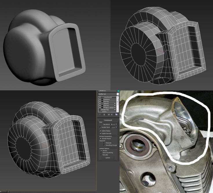
Use a Second Extruder
If your machine comes with 2 or more extruders, you can achieve a significant improvement by using a different material for your support structures. For example, it is quite common to print parts in PLA using water dissolvable PVA for the supports. Because the model and support structures are printed with different materials, they won’t bond together as easily, which allows you to do a better job of supporting the part. If you are using a different material for the support structures, you can frequently decrease your Upper Vertical Separation Layers to zero, and reduce your Horizontal Offset from the part to around 0.1mm. If you are interested in learning more about this technique, you can watch a more detailed video about the process here.
Related Topics
Diseño 3D online por Bitfab
Podemos ayudarte con el diseño 3D de tu proyecto, no tienes más que contactar con nosotros
Envíanos un mensaje
¿Prefieres aprender por ti mismo sobre diseño 3D? Sigue leyendo, te damos las claves 👇
¿Qué tipos de diseño 3D hay?
Diferentes estilos de diseño requieren diferentes herramientas. ¿Diseñas piezas mecánicas, industriales o artísticas?
Aquí tienes las diferencias entre el diseño tipo CAD y el orgánico, para que puedas elegir un programa de diseño 3D con el que empezar a diseñar.
Ya tendrás tiempo de fabricarlas después en nuestro servicio de impresión 3D online.
Diseño paramétrico o CAD
¿Quieres diseñar piezas mecánicas, para industria, para desarrollo de producto…? Entonces seguramente necesites diseñar piezas con diseño paramétrico o CAD.
Los software de diseño 3D paramétrico (como Fusion 360, nuestro favorito) permiten crear piezas mediante croquis, operaciones boleanas, agujereados, achaflanados, redondeados… ideal para crear las piezas que van a formar parte de tu producto.
Diseño orgánico o artístico
¿Tus diseños son artísticos, representan personas, animales, curvas y volúmenes orgánicos?
Entonces necesitas un software de diseño especializado en este tipo de diseño, como Blender, Meshmixer, Zbrush…
A partir de ahora podrás modelar en el ordenador cualquier forma que se te presente en tu cabeza.
¿Qué software de diseño 3D recomendamos?
Nuestra impresora 3D Bitfab Core diseñada en Autodesk Fusion 3DSi te tienes que quedar con una recomendación de software de diseño 3D de nuestra parte, quédate con el programa más completo que conocemos: Fusion 360.
Es el mejor software para piezas paramétricas por su relación calidad precio, por lo fácil que es de aprender y por la gran cantidad de herramientas que trae de serie: módulo para hacer planos, chapa plegada, simulación con elementos finitos, CAM para CNC y láser…
¿Gratis o de pago? Fusion 360 tiene versiones gratuitas para estudiantes y para startups que facturen menos de 100.000€ anuales. Incluso los precios que tiene son muy económicos comparado con otros software de CAD destinados a los profesionales.
Programas de diseño 3D para principiantes
2 programas online y sencillos para que te inicies en el diseño 3D sin tener que descargar nada. ¡No tienes excusa!
Tinkercad
Uno de los programas más sencillos de diseño 3D.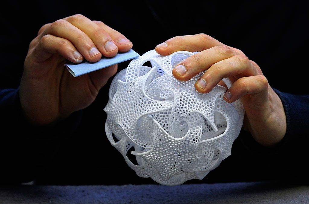
No te dejes engañar por los colores y el aspecto infantil, puedes diseñar piezas útiles para tu vida diaria en las primeras horas jugueteando con Tinkercad.
Tinkercad es el software que recomendamos desde Bitfab a los usuarios que están empezando, si no quieres usar Fusion.
Onshape
Onshape, diseño paramétrico online, sin descargar nada, potente y muy sencillo.
Tiene un plan gratis que te permite hacer tus primeras pruebas con el diseño 3D mecánico online.
Programas de diseño 3D para profesionales
Dos de los programas estándar en la industria (además de Fusion 360, que se está haciendo un hueco en las PYMES y startups), por si tu objetivo es aprender a diseñar en 3D para luego entrar a una empresa. CATIA también es muy popular en este nicho de mercado.
Son programas mucho más caros que pueden costar varias decenas de miles de euros al año, pero la mayoría tienen versiones para estudiantes por si quieres aprender a usarlos.
Solidworks
Inventor
Programas de diseño 3D orgánico
Meshmixer
Blender
Diseño optimizado para impresión 3D
¿Conoces el concepto de Diseño para Impresión 3D o Diseño para Fabricación Aditiva?
Cada tecnología de manufactura tiene sus particularidades, como sabrás no es lo mismo fabricar una pieza para ser mecanizada que inyectada que fabricada por capas. Con esto en mente hemos creado un ebook gratis para aprender a diseñar para impresión 3D FDM.
El libro contiene recomendaciones y trucos para optimizar tus diseños para ser fabricados con impresoras 3D de tecnología FDM (la tecnología de impresión 3D más popular y barata).
¡Descárgalo gratis!, es la manera más rápida de prepararte para imprimir tus diseños en 3D.
¡Estoy preparado para fabricar mis diseños!
¡Ha llegado el momento de que des el último paso y empieces a fabricar tus propios diseños! La especialidad de Bitfab es fabricar prototipos y series cortas de makers, inventores y emprendedores como tú.
Ponte en contacto para que te ayudemos a fabricar tu producto con las tecnologías de fabricación que ponemos a tu servicio. Te aconsejaremos sobre cual es la más adecuada para tu proyecto.
Consulta con nosotros tu proyecto
Enviar mensaje
Problems, defects, 3D printing errors and solutions
Often during the operation of a 3D printer, problems may arise due to which defects appear on the finished model. Or instead of a neat product, plastic noodles suddenly appear on the table.
In fact, the causes of defects can be conditionally divided into 2 types - these are physical and software.
Physical ones are those that arise due to problems with the mechanics or any other causes that can be eliminated physically. These include problems with printer mechanisms (belt tension, backlash), clogged or deformed nozzle, incorrect table geometry, etc.
Software - these are defects that occur due to incorrect slicer settings or, less often, errors in the printer firmware. For example, incorrectly selected print speed, retract settings, incorrectly selected temperature for plastic, etc.
Very rarely, the problem may lie in the wrong or “flying” printer firmware (although usually the printer simply will not start then), overheating of some boards during printing, etc. These are rather special cases, so we will not consider them.
Model peels off or does not stick to the build plate
This is the most common 3D printing problem. Every 3D printer has had a case when the first layer treacherously rolls, clinging to the extruder, or the most offensive - when it tears off a partially printed model from the table. The first layer must stick tightly otherwise nothing will be printed.
Gap between table and nozzle 9 too large0023
This is the most common reason. You just need to set the correct gap between the table and the nozzle.
Modern printers often use an auto-calibration (auto-leveling) table system or an auxiliary table leveling program. To calibrate such printers, use the instructions. If there is no manual, it can be downloaded from the manufacturer's website.
If you have a simple printer without auto-calibration, a self-assembly or KIT kit, use a probe or a piece of paper folded in half to calibrate. The probe should be slightly pressed against the table by the nozzle. Before calibration, the table and extruder must be heated. Align the table surface over each adjustment screw (there may be 3 or 4) in turn, and only then check the center point.
If you're having trouble getting your table surface perfectly level, try raft printing. Raft is a thick substrate in several layers that is printed under the model. It will help smooth out the slight curvature of the table.
A small cheat sheet to determine the correct gap on the first layer
Plastic with poor adhesion
Some types of plastic, due to various reasons, such as large shrinkage, do not adhere well to the surface of the printing platform. In this case, try using stickers or special 3D adhesives to improve adhesion between the table and the first layer of plastic.
In the early days of 3D printing, there were experiments with different homemade 3D adhesive recipes. ABS diluted in acetone, BF glue, sugar syrup and even beer. Some experiments have been successful. Until now, some enthusiasts use some types of hairspray or glue sticks as 3D glue. But still they are inferior in their properties to industrial 3D adhesives.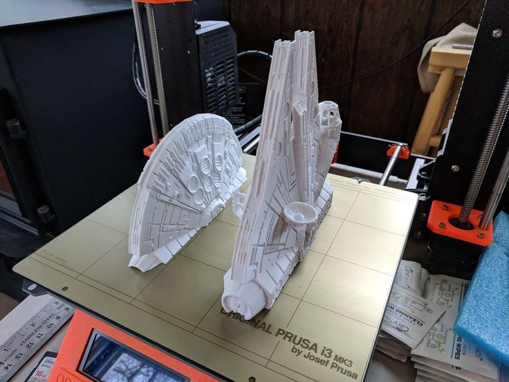
Some types of high temperature plastics with a high percentage of shrinkage (ABS, Nylon, etc.) may peel off the table during printing. This is due to uneven cooling and “compression” of the model (the lower layers have already cooled down, but the upper ones have not yet). For such plastics, it is imperative to use a 3D printer with a heated table and a closed case.
Plastic temperature too low
The hotter the plastic is when it exits the nozzle, the better it will adhere to the print bed. It is better to print the first 5-10 layers at a higher temperature (+ 5-10 degrees) and turn off the blower fan.
Wrong first layer settings (speed and thickness)
A thicker layer sticks easier, so the standard first layer is 0.3mm thick. With an increase in print speed, the heating block may simply not have time to heat the plastic to the desired temperature and it will stick to the table worse. Before printing, check the speed and thickness settings of the first layer in the slicer.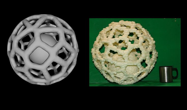
A lot depends on how the 3D printer prints the first layer. Try to control the printing of the first layer and only then leave the printer to work alone.
Plastic does not choke from nozzle
The printer has already begun to print, but the print table remains empty. Or part of the model did not print.
Clogged nozzle
In 3D printing, a nozzle is a consumable. The nozzles are clogged or worn out (frequency depends on the type of plastic). The simplest thing is to replace the nozzle. But if there was no spare at hand, you can try to clean the old one. To do this, there is a whole set of thin needles. Or you can heat a clogged nozzle above the melting point of the plastic and “burn out” the blockage. But later it is still better to replace the nozzle.
Low temperature nozzle
You need to increase the temperature of the extruder in the slicer settings or check the thermistor and heating block. Sometimes the thermistor may not read the temperature correctly due to a malfunction or incorrect 3D printer firmware settings.
If the problem occurs after replacing the thermistor - contact the manufacturer or read articles about PID tuning.
Empty extruder
As the extruder heats up, plastic begins to ooze out of the nozzle. Because of this, the extruder may start printing half empty. Because of this, part of the first layer is not printed. You can push the plastic manually by simply pushing the bar into the nozzle. Or solve this problem programmatically - in the slicer, add a contour print around the model (one line).
Some manufacturers and 3D enthusiasts add a line print on the edge of the table at the beginning of each GCode. This is done so that there is plastic in the nozzle by the time the model is printed.
Feed mechanism does not push through plastic
The plastic pushes the feed mechanism to the extruder - a motor with a special pulley put on the shaft. If for some reason the plastic is not pushed through (nozzle clogged, extruder temperature low, etc.), then the pulley “gnaws” through the bar. You need to push the plastic bar with your hands or cut off the damaged piece.
Elephant foot
The first layers of the model are wider and protrude beyond the boundaries of the model. This is due to the fact that the upper layers put pressure on the first ones that have not yet cooled down and flatten them.
High table temperature
Due to the too high temperature of the table, the lower layers remain soft for a long time. Try lowering the table temperature. It is better to reduce gradually (in increments of 5 degrees). You can try to turn on the blower when printing the first layers.
Small gap between nozzle and platen
If, when printing the first layer, the nozzle is too close to the table, then excess plastic will be forced out. After a few coats, this will not be as noticeable, but can lead to the effect of an “elephant's foot”.
Plastic re-extrusion
When too much material is squeezed out of the nozzle, the walls of the model are not smooth, but bumpy, with sagging.
The solution is software - in the settings of the slicer, you need to set the material feed rate (fluidity) to a lower value. The average value is 95-98%.
It is worth checking the diameter of the rod. If its size is greater than 1.75, then the plastic will be squeezed out more than necessary.
Plastic underextrusion
The plastic is squeezed out too little, because of this, gaps may appear between the layer. The finished model will be fragile and fragile.
Wrong thread diameter
Check the filament diameter in the slicer settings. Sometimes, instead of the popular 1.75, the default is 2.85.
Incorrect feed rate settings
Check the fluidity settings in the slicer. The average should be 95-98%.
Clogged nozzle
Something could get into the nozzle and partially block the exit of the plastic. Visually, the plastic will choke from the nozzle, but in a smaller amount than necessary for printing.
Hairiness or cobwebs on finished model
Thin threads of plastic protrude from the outer wall of the model (most often on one side). The defect appears due to the flow of plastic from the nozzle during idle movement.
Insufficient retract
A retract is a slight pull of a plastic filament from an extruder. Due to the retract when the extruder is idle (from layer to layer or from model to model), heated plastic does not drip from the nozzle. For some flowable plastics (eg PETG) the speed and amount of retraction must be increased.
"Hairiness" can be easily removed by grinding or cutting off the threads with a sharp scalpel.
High temperature extruder
The higher the extruder temperature, the more liquid the plastic becomes. It is important to find a balance so that the plastic is not too liquid and sticks well in layers.
In the selection of the optimal extruder temperature, a test model - a tower - helps a lot. It clearly shows how plastic behaves when printed at different temperatures.
.
Temperature test
Top "perforated" or uneven
The top of the model is bumpy or with holes. The problem may arise if the top of the model is flat. For example, like a cube.
Insufficient airflow
When printing the top plane (cover), the plastic does not have time to cool down and remains too liquid. Because of this, the threads are torn and holes are formed. Increase the fan speed on the last layers.
Few top layers
The top of the print may be too thin and deform as a result. Check slicer settings. The number of upper layers is not recommended to be set less than 6.
Low percentage of filling
If the infill percentage is too low, then the top layer will simply have nothing to rely on. Increase the fill percentage in the slicer settings.
Model deformation
Some parts of the model seem to have melted in some places or on one side. The problem most often occurs when printing with PLA plastic. The defect appears due to the fact that the plastic does not have time to cool and deforms.
Insufficient airflow model
Turn the fans on to maximum. If their power is not enough (in some printers, the fan is located only on one side), you can put a regular desktop fan and direct it to the 3D printer table.
Small model
Small models are difficult to blow well. Try to print small items alongside larger ones, or place several identical models in different corners of the table. So the plastic will have more time to cool.
Layer offset
Layers shift along the x or y axis during printing.
Print head jam
Turn off the printer and try to move the extruder along the x and y axes with your hands.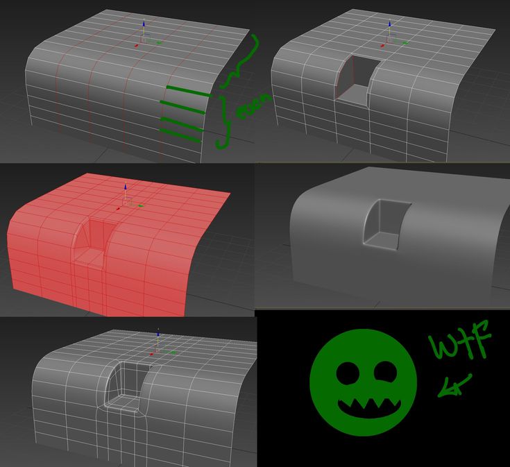 The extruder must move freely. If there are jams, check the mechanics of the printer. Bearing wear or the curvature of the shafts may be to blame.
Electronics overheating
Sometimes electronics problems can be to blame for misaligned layers. The most common cause is overheating of the drivers or too low current exposed to them.
Table top is loose
This is most often seen in 3D printers with glass. During printing, the nozzle may hit the model and move the glass slightly. Before printing, check if the glass or other printing surface is well fixed on the heating table.
Skip layers
Small holes are visible on the print, or the shell of the model is not continuous.
Teflon tube deformed
There are 2 types of thermal barriers - all-metal and with a Teflon tube. If overheated, the Teflon tube may deform. Plastic will pass through it, but in a smaller amount.
Low extruder temperature or high print speed
If the extruder is not heated enough, then the plastic will not be liquid enough and simply will not have time to be forced through the nozzle. The higher the print speed, the higher the extruder temperature should be.
Sometimes the outer walls print well, but the infill is “torn”. In this case, slow down the infill print speed in the slicer.
Model bundle
Cracks form on the surface of the printout during or after printing. Cracks can be large or very small. Most often, this problem occurs with plastics with a high percentage of shrinkage - ABS or Nylon.
Sudden temperature difference (if model delaminates during printing)
With a sharp temperature difference (for example, a draft), part of the model cools down faster. This leads to uneven shrinkage and incorrect distribution of internal stress. For plastics with low shrinkage, this is not critical.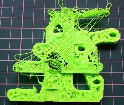 But if the shrinkage percentage is more than a few percent, the model may burst in layers.
For printing with such plastics, it is recommended to use a printer with a closed housing. If this is not possible, try to avoid drafts and sudden temperature changes in the room where the 3D printer prints as much as possible.
Print temperature
Due to too low printing temperatures, the layers may not “stick” well to each other. Raise the print temperature in the slicer settings.
Hardening (if the model cracks after printing)
Sometimes cracks appear on the model a few days after printing. This is due to uneven distribution of internal stress after cooling. You can try to “harden” the finished product.
For hardening, the model is placed, for example, in an oven, and heated to the softening temperature of the plastic. After that, the heating is turned off and the oven is left to cool slowly with the model inside. Due to this, the stress inside the print is distributed more evenly. But accuracy is very important in this method - if you make a little mistake with the temperature, the finished product can “float”.
Ringing
In places where the extruder changed direction, ripples are visible. Most often it looks like a shadow around the “sharp” protruding elements of the model.
Mechanical problems
Sometimes the problem occurs due to extruder play. Check if the extruder mount to the rails is loose. Be sure to check the tension of all belts.
High print speed or high accelerations
Moving the extruder too fast can cause vibrations that cause ripples on the wall of the model. The lighter the weight of the extruder, the less noticeable the ripples will be. To get rid of ringing, simply reduce the print speed in the slicer settings.
Slits for thin-walled models (not solid shell)
The thin wall of the model is not solid, but consists of two thin walls with a narrow gap between them. This problem is often faced by fans of printing "cutting" for baking.
Left model with wall defect, right without
Wall thickness and nozzle diameter mismatch
If the wall thickness is 1 mm, and the nozzle diameter is 0.4, it turns out that for a solid wall, 2 nozzle passes are few, and 3 are already many. The result will depend on the slicer algorithm, but most often you will get 2 walls with a thin slot in the middle (the slicer cannot change the wall thickness). The solution to the problem may be a slight refinement of the 3D model or the use of a different slicer.
Algorithms for calculating 3D models are constantly being improved and refined, and now this problem is less common.
When modeling, take into account not only the thickness of the nozzle, but also the percentage of “overlapping” of lines on each other. If you have a nozzle with a diameter of 0.4 - make the wall in your model not 0.
8, but 0.7 - 0.75.
Wrong model geometry
When instead of a circle you get an oval, and instead of a square you get a semblance of a rhombus.
The main reason is malfunctions in the mechanics of the printer. Be sure to check:
Belts
Check belt tension in x and y. Belts stretch over time and may need to be tightened or replaced. Each 3D printer has its own way of tightening the belt. If the belts are slightly stretched, you can tighten them with the help of a "spring".
Loose pulleys, etc.
Check if all bolts and nuts are tight. Are there backlashes. Pay special attention to tightening the pulleys located on the motors along the x and y axes.
Sagging of some parts of the model
Some parts are not printed, broken, or instead of a neat surface, a swollen plastic snot is obtained.
No support for overhangs
A 3D printer cannot print in the air, so if there are overhanging elements in the model, you need to set supports - supports.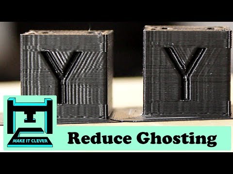 The slicer can set the necessary support itself, you need to check the appropriate box in the settings.
When printing with soluble support, you can set the gap between the model and support - 0. This will make the surface smoother. If the support material and the model are the same, you need to add a small gap. Otherwise, it will be difficult to separate the support from the model.
Split model
Sometimes the supports can take more plastic than the model. In this case, to save material and time, it will be more convenient to cut the model. If you have more than one 3D printer, then the model will print several times faster.
When cutting the model, you can leave grooves or mortgages so that the pieces of the model are connected without displacement.
Totals
In this article, we talked about the most popular 3D printing defects and how to solve them. Don't be intimidated by such a long list. Some problems are rare and you are unlikely to encounter them.
There is a list of problems that arise due to the design features of a 3D printer, so try to choose a printer that suits your needs. To do this, you need to understand what products and what material you need.
Problems associated with printing algorithms are quickly eliminated by software developers.
Do not be afraid of possible difficulties and each print will be successful.
Troubleshooting 3D printing・Cults
This article should help you identify various 3D printing problems. Find the image or description in this list that best describes the problem you're experiencing. We offer some tips that should help you solve this problem.
As you know, 3D printing is an empirical process and it is through mistakes that you learn to understand, set up and use your machine. With the help of this list, you should be able to resolve the major bugs. If you are still experiencing issues or have additional tips to add to this list, feel free to contact us and let us know!
#1 Drooling
Symptom
Thin threads are woven into gaps between different parts of a 3D printed part.
Common Name: oozing
Possible Cause
Plastic continues to leak out of the head as it moves due to residual pressure in the heater and fluidity of the molten plastic.
Suggested remedies
Increase filament retraction length in Slic3r, retraction distance in CuraEngine. Retracting the filament will cause the pressure in the print head heater to drop. The effect can be modulated by adjusting the retraction speed directly in the slicer.
Increase print head speed. This allows the melted plastic to spread less time and leave marks between the printed parts.
Reduce the extrusion temperature of your plastic. If it is too high, the plastic becomes more fluid and flows out of the extruder faster.
#2 It is collapsing
Symptom
Collapse or poor quality of the overhanging surface, leaving small bumps.
Common name: overhang
Possible cause
The plastic deposited on the periphery of the protrusion does not solidify fast enough, so the deposited filament moves before it solidifies. The phenomenon is repeated or emphasized from one layer to another.
Suggested fixes
Vent the deposited plastic more efficiently, for example by adding a fan to the extruder or directly with a portable fan.
Create print supports under the overhangs.
Reorient the part to avoid overhangs.
#3 Flaky sides or top
Symptoms
Contours not bonded enough.
Flat surfaces are not completely covered.
Possible cause
Not enough material is deposited. Too narrow, the deposited wires do not touch each other enough and therefore do not stick to the adjacent wire.
There is dirt in the nozzle, which prevents the passage of the melt.
The extrusion temperature is too low, the wire dries out too quickly or shrinks and therefore does not stick to the adjacent wire.
Suggested Tools
Calibrating the extruder to obtain material flow according to data received from the slicer.
Unlock the extrusion nozzle.
Increase extrusion temperature.
Increase the blending speed in your slicer.
#4 Not enough material on thin parts
Symptom
The edges of a very thin area are not strong enough, not enough material.
Possible cause
Recycling or reworking is not effective enough.
Incorrect filament solidification.
Slippage of the thread drive during retraction.
Suggested remedies
Reduce the retraction speed and length while printing.
Increase "extra leg length when retracting" when using Slic3r.
Increase the spring pressure on the driven gear.
#5 Blisters
Symptom
Blisters, mismatched geometry, such as small bumps that are seen mostly in areas with a small surface area.
Possible cause
The filament is too hot during extrusion or the filament cooling system is not effective enough.
Suggested media
Place more parts on the plate while printing. In this case, the nozzle will print more objects and therefore allow more time for the part to cool before passing over it again.
Improve the cooling of your 3D printed object by adding cooling systems.
#6 Thin walls delaminate
Symptom
At a thin wall without filler, the threads diverge, they are not glued together on the sides.
Possible Cause
The walls of your 3D print are too thin or they don't fit so small.
Suggested tools
Draw thicker walls to adapt to the thread thickness.
In the slicer settings, set a sludge width that is a sub-multiple of the wall width while remaining consistent with the extrusion diameter and layer height.
Change slicer.
#7 Layer shifts horizontally
Symptom
The layer is shifting in the X or Y axis (or both).
Possible Cause
Print head or plate movement problem.
Suggested fix
Reduce the acceleration on the axis that has the problem.
#8 Layers shift evenly
Symptom
Layers almost always shift along the X and/or Y axis after a certain print height.
Possible Cause
Head or plate offset failure due to overheating of motors going into safe mode.
Suggested fix
Cool engines with cooling systems (fans).
#9 Corners curl up
Symptom
Deformation in Z direction during 3D printing. This figure increases in case of a strong overhang.
Common name: curling
Possible cause
Poor curing, shrinkage effect due to temperature difference of the wire deposited on the previous cooled layer.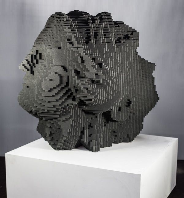
Suggested Solutions
Increase slope in the 3D part to reduce overhang.
Further cooling of the deposited plastic using a ventilation system.
Add print supports to affected areas.
#10 Corners fall off
Symptom
The corners of the printed object are peeling off the plate, creating an uneven base.
Common name: warping
Possible cause
Poor fit between workpiece and insert.
Material shrinkage factor too high.
The first layer is not pressed enough against the board.
Suggested Solutions
Change media as PLA is less likely to warp.
Apply adhesive to the printing plate (glue, tape, varnish, etc.).
Correctly adjust the plate height before printing.
Apply a thinner first layer to further crush the deposited wire.
Add a bezel under the first layer.
Heat up the stove.
Clean and degrease the base.
Change the filling strategy. Fill the bottom concentrically instead of linearly, then fill the inside in a honeycomb pattern to avoid any shrinkage effect.
Reduce the internal fill density of your 3D printed object.
#11 Extrusion density too low
Symptom
Incorrect material density.
Possible cause
Material consumption too low
Suggested remedies
Unlock the extrusion nozzle.
Filament blocked upstream of extruder (e.g. spool assembly)
Check thread drive (e.g. knurled screw problem)
Corners #12 not forming correctly
Symptom
The corners are not straight enough, they can even stick out and increase the size of the part.
Possible Cause
Too much material is deposited in the corner because the nozzle slows too much as it passes through the corner.
Suggested remedies
Intentionally soften the corner of the part in the 3D modeling software.
Increase the "jerk" on your 3D printer's axis control.
#13 There are black drops
Symptom
Burnt (blackened) plastic in some areas of the printed object.
Possible Cause
Poor nozzle seal causing burnt PLA or ABS to drip around the nozzle.
Suggested fix
Remove the nozzle and close it again.
#14 Layers poorly welded
Symptom
Part breaks at attachment point between two printed layers.
Possible cause
Too much cooling, the deposited layer does not adhere well to the previous layer, because it was not hot enough during the deposition.
Suggested remedies
Reduce fan speed during printing.
Increase the minimum print speed in the slicer.
#15 Bubbles form on the first layer
Symptom
The first layer comes off the plate locally in the form of bubbles.
Possible Causes
Moisture present in the material which gradually evaporates upon contact with the heating plate.
Insufficient heating plate temperature for the material being used.
Suggested products
Store raw material rolls in a dry place, in closed packaging, with a desiccant bag.
Dry damaged material: place in a rotary oven at 40°C for approximately 3 hours. Be careful not to heat above 45°C or 50°C as this may cause the threads to stick together in the bobbin and even lose their cylindrical shape.
Increase the temperature of the heating plate.
Printing on tape or special adhesive.
#16 Fragile top and bottom
Symptom
Horizontal sides too thin and brittle.
Possible Causes
Insufficient material thickness above and below thin fill print. The laid threads have too few support points and break between the threading ribs.
Suggested products
Place at least 2 or 3 fully filled layers ("Solid layers" option in Slic3r) for the "top" and "bottom" faces.
Increase the fill of your object.
#17 Hole tops collapse
Symptom
Horizontal center hole top wires collapse during construction.
Possible causes
Plumb line too horizontal.
Mismatch between nozzle temperature, wire cooling and speed.
Suggested fixes
Reduce or eliminate this overhang area by modifying the 3D file geometry. An example is in the large hole in the photo, shaped like a drop of water, not a cylinder.
Add print supports below this area if the ledge is too difficult for the 3D printer.
Avoid too much slowdown in this area, even if the layer print time is short.
#18 Color or clarity varies
Symptom
The color or transparency of the material changes in different areas during 3D printing.
Possible causes
Different crystallization of the material due to different cooling rates. This may be due, for example, to the printing time of individual parts of the object or to the power of the fan.
Radiation from the nozzle can affect the thermal cycle of the previous layer and thereby change its appearance.
The applied layer is too hot because the underlying layer has not had time to cool.
Be careful, the physical-mechanical properties of the part may change due to these differences in crystallization!
Suggested fixes
Better control of cooling with slicer settings: change fan power based on plate cooling time or slow print speed in proportion to plate surface.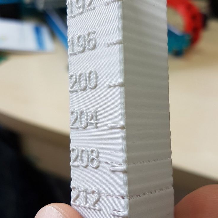
Reduce extrusion temperature for faster and more uniform phase transition.
#19 Layers are delaminating
Symptom
Some layers are flexing and cracks appear between the different printed layers.
Possible causes
Twisting phenomenon due to the effect mentioned in #9 the above happens between layers.
The wire cools too quickly at the exit of the nozzle, it does not weld properly with the previous layer.
Severe contraction of the material during cooling or phase change.
Some materials extruded at high temperature (ABS, PC...) may present a significant shrinkage phenomenon.
Suggested remedies
Change the extrusion temperature.
Change the media.
Avoid blowing on a deferred wire, reducing fan power, or placing the printer in a draughty room.
Close the assembly area in a controlled cabinet at a temperature close to the glass transition temperature of the material.
#20 Drops appear
Symptom
Drops of material are deposited at various points on the side surface of the 3D printed object.
Possible causes
Excessive extrusion when resuming extrusion after stopping extrusion when moving from one point of the part to another or when changing layers.
Suggested Remedies
Some slicers have a setting that allows, after a pause in printing, to request that more be pushed in before resuming normal printing than was removed by retraction.
#21 Bowden extruder salivation
Symptom
Extruder Bowden is either running too hard or not running enough. First impressions of your extruder are not great, too much extruded material, bridges between different areas in motion where extrusion should stop.
Possible cause
Insufficient thread shrinkage to compensate for gap in Bowden tube. Depending on the diameter of the tube and filament, as well as the length of the body, the motor must draw a certain length of filament through the bends of the tube before the filament is drawn out of the heating head.
Suggested fixes
Increase the "pull" distance in the slicer. The detail on the left was printed with 1.5 mm of indentation, which was clearly not enough. When the pull-in distance was increased to 6mm, the center part was printed. Too much shrinkage causes hot material to enter the thermal break, the temperature of the thermal break gradually rises, and the melting thread eventually gets stuck in the thermal break. The engine is no longer able to effectively push it. Reducing the retraction distance to 4 mm results in the part shown on the right.
#22 Streaks or regular patterns on extrusion
Symptom
Repeating patterns appear on the walls of 3D prints.
The pattern may change depending on the direction of movement of the motors.